

Avdel 07611, 07613, 07614 Instruction Manual
P n e u m a t i c P o w e r T o o l
Pass onto user to read and keep for reference
I n s t r u c t i o n M a n u a l
0761 type
07611 - 07613 - 07614

AVDEL policy is one of continuous development. Specifications shown in this document may be subject to changes which
may be introduced after publication. For the latest information always consult Avdel.
S P E C I F I C A T I O N S F O R 0 7 6 1 T Y P E T O O L
■
■
■
■
■
■
■
■
■
■
■
■
■
■
■
■
■
■
■
■
■
■
■
■
■
■
■
■
■
■
■
■
■
■
■
■
■
■
■
■
■
■
AIR PRESSURE Minimum - Maximum 5 - 7 bar 70 - 100 lbf/in
2
FREE AIR VOLUME REQUIRED @ 5.4 bar / 80 lbf/in
2
3.5 litres 0.12 ft
3
STROKE 07611 Minimum 25.4 mm 0.95 in
07613/4 Minimum 17.3 mm 0.68 in
PULL FORCE 07611 @ 4.8 bar / 70 lbf/in
2
10.91 kN 2450 lbf
07613/4 @ 5.4 bar / 80 lbf/in
2
18.68 kN 4200 lbf
CYCLE TIME 07611/3 Approximately 1.5 seconds
07614 Approximately 1.3 seconds
NOISE LEVEL 07611 73 dB(A)
07613/4 Less than 70 dB(A
WEIGHT 07611 Without nose equipment 2.7 kg 6 lb
07613/4 Without nose equipment 3 kg 6.6 lb
VIBRATION 07611/4 2.6 m/s
2
8.5 f/s
2
07613 Less than 2.5 m/s
2
8 f/s
2

C
O N T E N T S
C
O N T E N T S
1
S A F E T Y
I N T E N T O F U S E
P U T T I N G I N T O S E R V I C E
N O S E A S S E M B L I E S
S E R V I C I N G
P R I M I N G
F A U L T D I A G N O S I S
General
2
Specific to 0761 Tool
3
Selection & Dimensions
4-5
Air Supply
6
Operating Procedure
6-7
Accessories
7
Fitting/Servicing/Components
8-9
Daily, Weekly
10
Service Kit
11
Total Maintenance
11-13
07611 General Assembly & Parts List
14-15
07613 & 07614 General Assembly & Parts List
16-17
Oil Details & Priming Procedure
18
Symptom, Cause & Remedy
19

S
A F E T Y
2
This instruction manual must be read with particular attention to the following safety rules,
by any person installing, operating, or servicing this tool.
DO NOT USE OUTSIDE THE DESIGN INTENT.
DO NOT USE EQUIPMENT WITH THIS TOOL/MACHINE OTHER THAN THAT
RECOMMENDED AND SUPPLIED BY AVDEL.
ANY MODIFICATION UNDERTAKEN BY THE CUSTOMER TO THE TOOL/MACHINE,
NOSE ASSEMBLIES, ACCESSORIES OR ANY EQUIPMENT SUPPLIED BY AVDEL OR THEIR
REPRESENTATIVES, SHALL BE THE CUSTOMER'S ENTIRE RESPONSIBILITY. AVDEL WILL BE
PLEASED TO ADVISE UPON ANY PROPOSED MODIFICATION.
THE TOOL/MACHINE MUST BE MAINTAINED IN A SAFE WORKING CONDITION AT
ALL TIMES AND EXAMINED AT REGULAR INTERVALS FOR DAMAGE AND FUNCTION BY
TRAINED COMPETENT PERSONNEL. ANY DISMANTLING PROCEDURE SHALL BE
UNDERTAKEN ONLY BY PERSONNEL TRAINED IN AVDEL PROCEDURES. DO NOT DISMANTLE
THIS TOOL/MACHINE WITHOUT PRIOR REFERENCE TO THE MAINTENANCE INSTRUCTIONS.
CONTACT AVDEL WITH YOUR TRAINING REQUIREMENTS.
THE TOOL/MACHINE SHALL AT ALL TIMES BE OPERATED IN ACCORDANCE WITH
RELEVANT HEALTH AND SAFETY LEGISLATION. IN THE U.K. THE “HEALTH AND SAFETY AT
WORK ETC. ACT 1974” APPLIES. ANY QUESTION REGARDING THE CORRECT OPERATION
OF THE TOOL/MACHINE AND OPERATOR SAFETY SHOULD BE DIRECTED TO AVDEL.
THE PRECAUTIONS TO BE OBSERVED WHEN USING THIS TOOL/MACHINE MUST BE
EXPLAINED BY THE CUSTOMER TO ALL OPERATORS.
ALWAYS DISCONNECT THE AIRLINE FROM THE TOOL/MACHINE INLET BEFORE
ATTEMPTING TO ADJUST, FIT OR REMOVE A NOSE ASSEMBLY.
DO NOT OPERATE A TOOL/MACHINE THAT IS DIRECTED TOWARDS ANY PERSON(S).
ALWAYS ADOPT A FIRM FOOTING OR A STABLE POSITION BEFORE OPERATING THE
TOOL/MACHINE.
ENSURE THAT VENT HOLES DO NOT BECOME BLOCKED OR COVERED AND THAT
HOSES ARE ALWAYS IN GOOD CONDITION.

3
In addition to the general safety rules opposite, the following specific safety points must also
be observed:
THE OPERATING PRESSURE SHALL NOT EXCEED 7 BAR - 100 LBF/IN2.
DO NOT OPERATE THE TOOL WITHOUT FULL NOSE EQUIPMENT IN PLACE.
CARE SHALL BE TAKEN TO ENSURE THAT SPENT STEMS ARE NOT ALLOWED TO
CREATE A HAZARD.
0761 TOOLS MUST BE FITTED WITH AN UNDAMAGED STEM DEFLECTOR OR STEM
CATCHER BEFORE OPERATING. IF THE TOOL IS FITTED WITH A STEM CATCHER, IT MUST
BE EMPTIED WHEN HALF FULL.
IF THE 0761 TOOL IS FITTED WITH A STEM DEFLECTOR, IT SHOULD BE ROTATED UNTIL
THE APERTURE IS FACING AWAY FROM THE OPERATOR AND OTHER PERSON(S) WORKING
IN THE VICINITY.
WHEN USING THE TOOL, THE WEARING OF SAFETY GLASSES IS REQUIRED BOTH BY
THE OPERATOR AND OTHERS IN THE VICINITY TO PROTECT AGAINST FASTENER
PROJECTION, SHOULD A FASTENER BE PLACED ‘IN AIR’. WE RECOMMEND WEARING
GLOVES IF THERE ARE SHARP EDGES OR CORNERS ON THE APPLICATION.
TAKE CARE TO AVOID ENTANGLEMENT OF LOOSE CLOTHES, TIES, LONG HAIR,
CLEANING RAGS ETC., IN THE MOVING PARTS OF THE TOOL WHICH SHOULD BE KEPT
DRY AND CLEAN FOR BEST POSSIBLE GRIP.
WHEN CARRYING THE TOOL FROM PLACE TO PLACE KEEP HANDS AWAY FROM THE
TRIGGER TO AVOID INADVERTENT OPERATION OF THE TOOL.
EXCESSIVE CONTACT WITH HYDRAULIC OIL SHOULD BE AVOIDED. TO MINIMIZE
THE POSSIBILITY OF RASHES, CARE SHOULD BE TAKEN TO WASH THOROUGHLY.

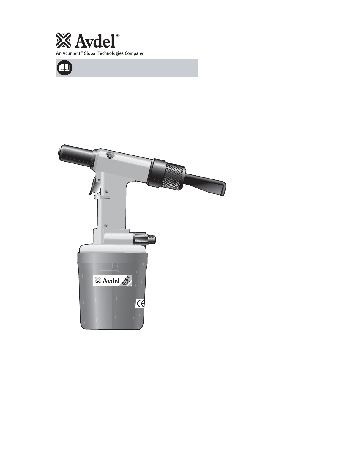
The hydro-pneumatic 0761 MkII type tool has three models each designed to place at high speed a different type of fastener as s hown
in the table below, making it ideal for batch or flow-line assembly in a wide variety of applications throughout all industries .
Throughout this manual we refer to the different models without adding ‘Mk II’ after the model number. It is important to remember
that all models describes in this manual are Mk II models and supersede original models. The MK II model for the 07611 start at serial
number 400 and at serial number 3001 for the 07613 and 07614 models.
All three models are supplied standard with a stem deflector and the option of a stem collector. For more details see the ‘Acc esssories’
section.
A complete tool is fitted with a fixed straight nose assembly suited to the fastener you wish to place and a priming pump is al so included.
See the Priming section for more details. It is also possible to order the base tool only, which is supplied without a nose as sembly or
a priming pump. For more details on the base tools, see the respective general assembly drawings and part lists.
To select the part number of a major item use the table below. For more component details of nose assemblies, see the ‘Nose Ass emblies’
section.
4
I
N T E N T O F U S E
hre
0761 TOOL SELECTION
FASTENER
TYPE SIZE
*
BASE TOOL
PART Nº
MATERIAL
NOSE ASSEMBLY
PART Nº
COMPLETE TOOL
PART Nº
TOOL
MODEL
07611 AVTAINER 9.53/
8
STEEL 07611-00200 07498-00800 07611-00001
07613 MAXLOK 4.8
3/16
STEEL & ALUMINIUM 07613-00200 07610-02000 07613-00001
6.4
1/4
STEEL & ALUMINIUM 07613-00200 07610-02100 07613-00002
07614 HEMLOK 6.4
1/4
STEEL & ALUMINIUM 07614-02000 07612-02000 07614-00002
*
Sizes in bold are millimetres. Other sizes are in inches.
Dimensions on the opposite page, particularly around the nose assembly area, will help you assess the accessibility of your app lication.
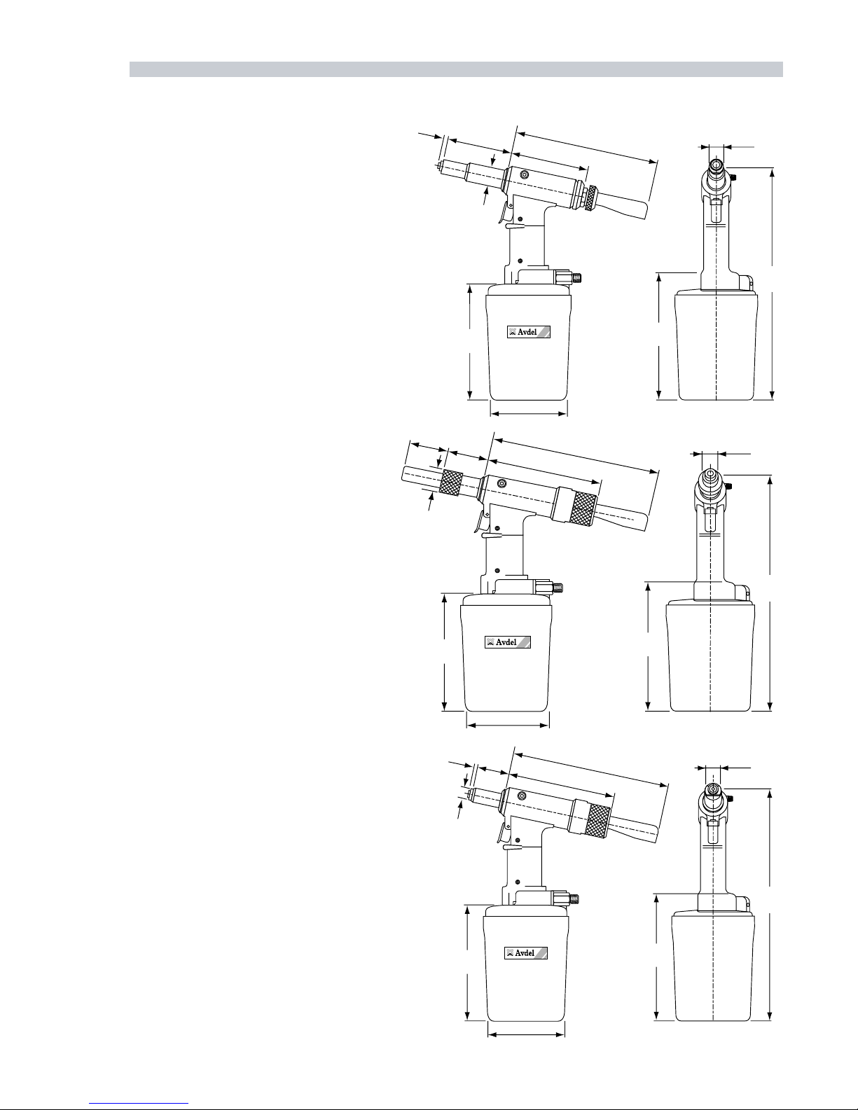
5
07611 - for AVTAINER fasteners
Dimensions shown in bold are millimetres.
Other dimensions are in inches.
152
6
114
4.5
324
12.75
19
0.75
64
1
57.
5
15
2
35
1.2
72
1.
1
6
12
5
.
8
175
6.9
1670
EPY
T
152
6
114
4.5
321
12.5
20
0.8
7
11
6.
4
0
1
2
5
2
.
8
175
6.9
6
9
9.3
4
61.
0
32
9.0
07613 - for MAXLOK fasteners
Dimensions shown in bold are millimetres.
Other dimensions are in inches.
07614 - for HEMLOK fasteners
Dimensions shown in bold are millimetres.
Other dimensions are in inches.
152
6
114
4.5
324
12.75
23
0.9
641
57.5
1
6
4.
2
6
12
5.8
175
6.9
5
.
3
41
.
0
41
6.0
6
P
U T T I N G I N T O S E R V I C E
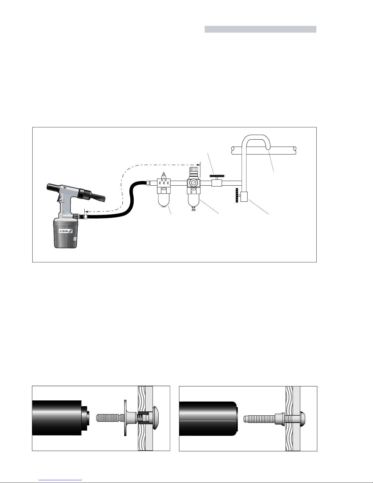
A I R S U P P L Y
All tools are operated with compressed air at an optimum pressure of 5.4 bar. We recommend the use of pressure regulators and
automatic oiling/filtering systems on the main air supply. These should be fitted within 3 metres of the tool (see diagram bel ow) to ensure
maximum tool life and minimum tool maintenance.
Air supply hoses should have a minimum working effective pressure rating of 150% of the maximum pressure produced in the system
or 10 bar, whichever is the highest. Air hoses should be oil resistant, have an abrasion resistant exterior and should be armou red where
operating conditions may result in hoses being damaged. All air hoses MUST have a minimum bore diameter of 6.4 mil limetres or 1/4 inch.
Read servicing daily details page 10.
8
6
4
2
0
0
1
2
1
41
6
1
TAKE OFF POINT
FROM MAIN SUPPLY
STOP COCK
(USED DURING MAINTENANCE
OF FILTER/REGULATOR OR LUBRICATION UNITS)
MAIN SUPPLY
DRAIN POINT
PRESSURE REGULATOR
AND FILTER
(DRAIN DAILY)
LUBRICATOR
3
M
E
T
R
E
S
M
A
X
I
M
U
M
O P E R A T I N G P R O C E D U R E
07611 model for AVTAINER
■ Ensure that the correct nose assembly is fitted.
■ Connect the tool to the air supply.
■ Push the Avtainer through the prepared hole in the application.
■ Slide the collar over the stem (orientation as shown below).
■ Keeping the head of the Avtainer against the application, place the
nose assembly of the tool over the protruding stem.
■ Fully operate the trigger. One cycle will ensure that the collar is
forced over the lock grooves of the stem and that the stem breaks
at the breaker groove.
■ Release the trigger. The tool completes its cycle by pushing itself off
the collar and ejecting the spent stem at the rear.
07613 model for MAXLOK
■ Ensure that the correct nose assembly is fitted.
■ Connect the tool to the air supply.
■ Push the Maxlok stem through the application hole .
■ Place the collar on the stem (orientation as shown below).
■ Keeping the head of the stem against the application, push the tool
onto the protruding stem.
■ Fully depress the trigger. One cycle will ensure that the collar is
swaged into the lock grooves of the stem and the the stem breaks
at the breaker groove.
■ Release the trigger. The tool completes its cycle by pushing itself off
the collar and ejecting the spent stem at the rear.
 Loading...