

Page 1

Avaya M-MLS
Routing Manager
User Guide
April 2002
Page 2

Avaya M-MLS Routing Manager User Guide
Copyright Avaya Inc. 2002 ALL RIGHTS RESERVED
The products, specifications, and other technical information regarding the products
contained in this document are subject to change without notice. All information in this
document is believed to be accurate and reliable, but is presented without warranty of any
kind, express or implied, and users must take full responsibility for their application of any
products specified in this document. Avaya disclaims responsibility for errors which may
appear in this document, and it reserves the right, in its sole discretion and without notice, to
make substitutions and modifications in the products and practices described in this
document.
Avaya™, Cajun™, P550™, LANstack™, CajunView™, and SMON™ are trademarks of
Avaya Inc.
ALL OTHER TRADEMARKS MENTIONED IN THIS DOCUMENT ARE PROPERTY OF THEIR
RESPECTIVE OWNERS.
Release 3.016
Page 3

Avaya M-MLS Routing Manager User Guide iii
Table of Contents
Preface . . . . . . . . . . . . . . . . . . . . . . . . . . . . . . . . . . . . . . . . . . . . . . . . . . v
The Purpose of this Guide . . . . . . . . . . . . . . . . . . . . . . . . . . . . . . . . . .v
Who Should Use this Guide . . . . . . . . . . . . . . . . . . . . . . . . . . . . . . . .v
Organization of this Guide . . . . . . . . . . . . . . . . . . . . . . . . . . . . . . . . vi
Chapter 1 — Introduction . . . . . . . . . . . . . . . . . . . . . . . . . . . . . . . . . . . 1
Starting Avaya M-MLS Routing Manager . . . . . . . . . . . . . . . . . . . . .1
Running Avaya M-MLS Routing Manager from Avaya MultiService Console
.1
Running Avaya M-MLS Routing Manager from HP NNM (UNIX or Windows NT)
2
Running Avaya M-MLS Routing Manager from HP-OV for Windows
.2
Avaya M-MLS Routing Manager User Interface . . . . . . . . . . . . . . . .3
Toolbar, Menu, and Shortcut Key Options . . . . . . . . . . . . . . . . .4
Working with the User Interface . . . . . . . . . . . . . . . . . . . . . . . . .5
Creating New Table Entries . . . . . . . . . . . . . . . . . . . . . . . . .5
Modifying Table Entries . . . . . . . . . . . . . . . . . . . . . . . . . . . .6
Deleting Table Entries . . . . . . . . . . . . . . . . . . . . . . . . . . . . . .6
Changing Default Values . . . . . . . . . . . . . . . . . . . . . . . . . . . . . . .6
Chapter 2 — Device. . . . . . . . . . . . . . . . . . . . . . . . . . . . . . . . . . . . . . . . 7
Device Global Parameters . . . . . . . . . . . . . . . . . . . . . . . . . . . . . . . . . .8
Upload/Download Configuration . . . . . . . . . . . . . . . . . . . . . . . . . . . .9
Selecting TFTP Secure Mode (In Solaris Only) . . . . . . . . . . .9
Uploading the Current Configuration to a File . . . . . . . . . .10
Downloading a Saved Configuration to the Router . . . . . .10
Upload/Download Configuration Parameters . . . . . . . . . .11
Traps Global Parameters . . . . . . . . . . . . . . . . . . . . . . . . . . . . . . . . . .11
Trap Managers . . . . . . . . . . . . . . . . . . . . . . . . . . . . . . . . . . . . . . . . .12
Reset . . . . . . . . . . . . . . . . . . . . . . . . . . . . . . . . . . . . . . . . . . . . . . . . .13
Chapter 3 — Layer 2 . . . . . . . . . . . . . . . . . . . . . . . . . . . . . . . . . . . . . . 14
Interfaces (VLANs) . . . . . . . . . . . . . . . . . . . . . . . . . . . . . . . . . . . . . .15
Bridge Global Parameters . . . . . . . . . . . . . . . . . . . . . . . . . . . . . . . . .16
Bridge Parameters . . . . . . . . . . . . . . . . . . . . . . . . . . . . . . . . . . . . . . .18
Chapter 4 — IP Route . . . . . . . . . . . . . . . . . . . . . . . . . . . . . . . . . . . . . 19
IP Global Parameters . . . . . . . . . . . . . . . . . . . . . . . . . . . . . . . . . . . . .20
Page 4

iv Avaya M-MLS Routing Manager User Guide
Table of Contents
IP Interfaces . . . . . . . . . . . . . . . . . . . . . . . . . . . . . . . . . . . . . . . . . . .21
Routing Table . . . . . . . . . . . . . . . . . . . . . . . . . . . . . . . . . . . . . . . . . .23
ARP Table . . . . . . . . . . . . . . . . . . . . . . . . . . . . . . . . . . . . . . . . . . . . .25
DHCP/BOOTP Global Parameters . . . . . . . . . . . . . . . . . . . . . . . . . . .26
DHCP/BOOTP Parameters . . . . . . . . . . . . . . . . . . . . . . . . . . . . . . . .28
RIP Global Parameters . . . . . . . . . . . . . . . . . . . . . . . . . . . . . . . . . . .30
RIP Interfaces . . . . . . . . . . . . . . . . . . . . . . . . . . . . . . . . . . . . . . . . . .31
OSPF . . . . . . . . . . . . . . . . . . . . . . . . . . . . . . . . . . . . . . . . . . . . . . . . .33
OSPF Global Parameters . . . . . . . . . . . . . . . . . . . . . . . . . . . . . .34
OSPF Interface Table . . . . . . . . . . . . . . . . . . . . . . . . . . . . . . . . .35
OSPF Area Parameters . . . . . . . . . . . . . . . . . . . . . . . . . . . . . . . .37
OSPF Link State Database . . . . . . . . . . . . . . . . . . . . . . . . . . . . .38
OSPF External Database . . . . . . . . . . . . . . . . . . . . . . . . . . . . . .40
OSPF Neighbor Table . . . . . . . . . . . . . . . . . . . . . . . . . . . . . . . . .41
Access Control Global Parameters . . . . . . . . . . . . . . . . . . . . . . . . . .43
Access Control Table . . . . . . . . . . . . . . . . . . . . . . . . . . . . . . . . . . . . .44
IP Redundancy Global Parameters . . . . . . . . . . . . . . . . . . . . . . . . . .46
IP Redundancy Table . . . . . . . . . . . . . . . . . . . . . . . . . . . . . . . . . . . .48
IP Multicast Global Parameters . . . . . . . . . . . . . . . . . . . . . . . . . . . . .49
IP Multicast Interfaces . . . . . . . . . . . . . . . . . . . . . . . . . . . . . . . . . . .51
IP Multicast Table . . . . . . . . . . . . . . . . . . . . . . . . . . . . . . . . . . . . . . .52
Chapter 5 — IPX Route . . . . . . . . . . . . . . . . . . . . . . . . . . . . . . . . . . . . 54
IPX Interfaces . . . . . . . . . . . . . . . . . . . . . . . . . . . . . . . . . . . . . . . . . .55
RIP Interfaces . . . . . . . . . . . . . . . . . . . . . . . . . . . . . . . . . . . . . . . . . .57
RIP Routing Table . . . . . . . . . . . . . . . . . . . . . . . . . . . . . . . . . . . . . . .58
SAP Interfaces . . . . . . . . . . . . . . . . . . . . . . . . . . . . . . . . . . . . . . . . . .60
SAP Services . . . . . . . . . . . . . . . . . . . . . . . . . . . . . . . . . . . . . . . . . . .61
SAP Filters Global Parameters . . . . . . . . . . . . . . . . . . . . . . . . . . . . .63
SAP Filters . . . . . . . . . . . . . . . . . . . . . . . . . . . . . . . . . . . . . . . . . . . .64
Access Control Global Parameters . . . . . . . . . . . . . . . . . . . . . . . . . .65
Access Control Table . . . . . . . . . . . . . . . . . . . . . . . . . . . . . . . . . . . . .67
Appendix A — Error Messages. . . . . . . . . . . . . . . . . . . . . . . . . . . . . . 69
Router Manager Error Messages . . . . . . . . . . . . . . . . . . . . . . . . . . .69
SNMP Errors . . . . . . . . . . . . . . . . . . . . . . . . . . . . . . . . . . . . . . . . . . .71
Page 5

Avaya M-MLS Routing Manager User Guide v
Preface
Welcome to Avaya M-MLS Routing Manager . This chapter provides
an introduction to the structure and assumptions of the guide. It
includes the following sections:
• The Purpose of this Guide - A description of the intended
purpose of this guide.
• Who Should Use this Guide - A description of the
intended audience of this guide.
• Organization of this Guide - A brief description of the
subjects covered in each chapter of this guide.
The Purpose of this Guide
This guide contains the information needed to operate
Avaya M-MLS Routing Manager efficiently and effectively.
Who Should Use this Guide
This guide is intended for use by network managers familiar with
network management and its fundamental concepts. It is assumed
that the user has the basic responsibility for monitoring Avaya
Inc.’s intelligent switching devices and the network traffic.
Page 6

Preface
vi Avaya M-MLS Routing Manager User Guide
Organization of this Guide
This guide is structured to reflect the following conceptual divisions:
• Preface - An introduction to Avaya M-MLS Routing
Manager.
• Introduction to Avaya M-MLS Routing Manager -
Instructions on how to start Avaya M-MLS Routing Manager
and a description of the user interface.
• Device - Enables you to display and modify global
parameters, reset the module, define managers to send or
prevent traps, and upload or download configuration
parameters.
• Layer 2 - Enables you to define manually and display layer 2
interfaces (VLANs and bridges) at the management station.
• IP Route - Enables you to display and update IP interfaces,
the IP routing table, the ARP table, DHCP/BOOTP
parameters, RIP interfaces, OSPF interfaces, area parameters,
link state database and neighbors, the IP access control table,
redundancy parameters, and multicast parameters.
• IPX Route - Enables you to display and update IPX
interfaces, RIP interfaces and routing table, SAP interfaces
and services, and the IPX access control table.
• Error Messages - A list of error messages that can occur in
Avaya M-MLS Routing Manager.
Page 7

Avaya M-MLS Routing Manager User Guide 1
1
Introduction
This chapter provides an introduction to Avaya M-MLS Routing
Manager. It includes the following sections:
• Starting Avaya M-MLS Routing Manager - Instructions on
how to access Avaya M-MLS Routing Manager from your
management platform.
• Avaya M-MLS Routing Manager User Interface - A
description of Avaya M-MLS Routing Manager’s user interface,
including instructions on using its features.
Starting Avaya M-MLS Routing Manager
This section provides instructions for starting Avaya M-MLS Routing
Manager.
Running Avaya M-MLS Routing Manager from Avaya
MultiService Console
To start Avaya M-MLS Routing Manager from Avaya MultiService
Console:
1. Select the Avaya M-MLS device you wish to work with.
2. Double-click the row representing the Avaya M-MLS device.
Or
Select
Tools > Device Manager.
Page 8

Chapter 1
2 Avaya M-MLS Routing Manager User Guide
Running Avaya M-MLS Routing Manager from HP NNM
(UNIX or Windows NT)
From the management platform map:
1. Select the M-MLS router you wish to work with.
2. Click in the OpenView toolbar.
Or
Select
Tools > Avaya > Device Manager.
Or
1. Right-click on the M-MLS router you wish to work with.
2. Select
Avaya: Device Manager.
Running Avaya M-MLS Routing Manager from HP-OV for
Windows
From the management platform map:
Double-click the icon representing the M-MLS router you wish to
work with.
Or
Select a M-MLS router, select
Avaya > Zoom. Avaya M-MLS Routing
Manager opens.
Page 9

Avaya M-MLS Routing Manager User Guide 3
Introduction
Avaya M-MLS Routing Manager User Interface
The Avaya M-MLS Routing Manager user interface includes:
• Menu Bar - Access to Avaya M-MLS Routing Manager
commands.
• Toolbar - Button shortcuts to Avaya M-MLS Routing Manager
commands.
• Shortcut Keys - Keyboard shortcuts to Avaya M-MLS Routing
Manager commands.
• The Main Window:
— The left side of the window displays a tree of folder icons,
representing various Avaya M-MLS Routing Manager
applications. When you select a folder , data is received from the
router, and the appropriate pane is displayed on the right.
— The top-right section of the window displays a table containing
all data associated with the selected folder . Some screens do not
contain a table.
— The bottom-right section of the window displays fields for the
selected table entry. To modify data in the fields, refer to
Toolbar, Menu, and Shortcut Key Options, and W orking with the User
Interface.
* Note: If your M-MLS device version is earlier than M-MLS 2.5, you
will not be able to access some of the screens mentioned in
this manual, and some of the screens will not contain all of
the documented parameters.
Page 10
Chapter 1
4 Avaya M-MLS Routing Manager User Guide
Toolbar, Menu, and Shortcut Key Options
The toolbar and menu provide access to the Avaya M-MLS Routing
Manager’s main functions. The table below describes the buttons on the
toolbar and provides the equivalent menu options and shortcut keys.
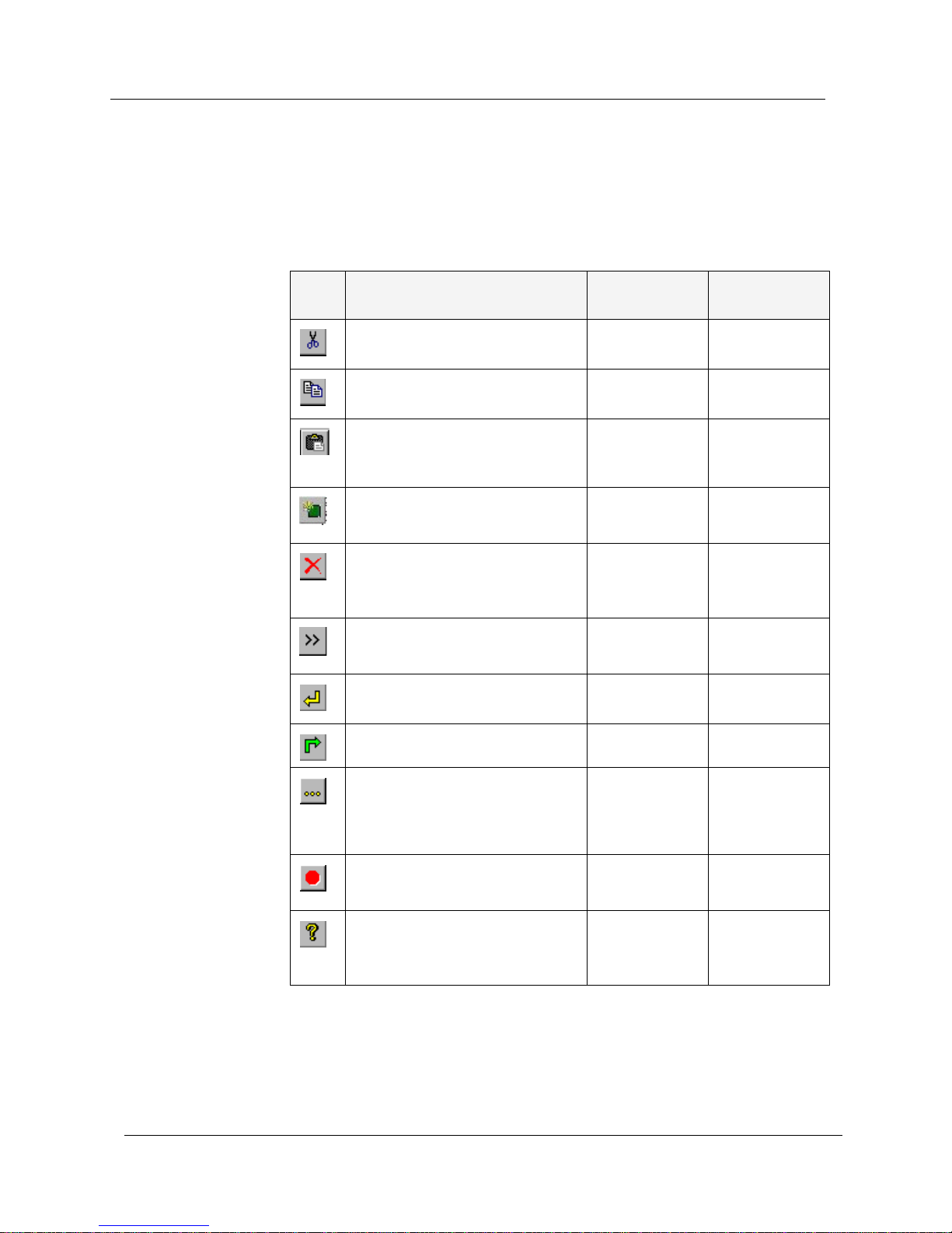
Table 1-1. Toolbar Buttons, Menu Options, and Shortcut Keys
Icon Description Menu
Shortcut
Key
Cuts a selected table entry to the
Clipboard.
Edit > Cut CTRL + X
Copies a selected table entry to
the Clipboard.
Edit > Copy CTRL + C
Pastes a cut or copied table
entry into the table as a new
entry.
Edit > Paste CTRL + V
Creates a new table entry
(where applicable).
List >
New Element
CTRL + N
Deletes the selected table entry
(where applicable).
List >
Delete
Element
Shows or hides extended fields
for the current window.
List >
Show/Hide
Refreshes the current screen
with data from the router.
Device >
Refresh
CTRL + R
Sends changes to the router. Device > Send CTRL + W
Opens a dialog box which
enables you to determine the
starting point in the display of a
table.
Device > Start
point
CTRL + F
Interrupts the display of table
information in large tables.
Device > Stop CTRL + Q
Provides access to on-line help. Help >
Contents
Page 11

Avaya M-MLS Routing Manager User Guide 5
Introduction
Working with the User Interface
The A v aya M-MLS Routing Manage r user interface enables you to cre ate,
modify, or delete table entries in selected windows.
You can make multiple changes to fields and checkboxes, and undo the
changes by clicking
Undo. When all changes are finalized, click to
update the router.
You can make multiple changes to table entries. Click
Enter to update the
table locally. The Avaya M-MLS Routing Manager interface informs you
of the status of each row in the table. The following table shows a list of
icons which may appear at the start of a table row, with their
corresponding explanations.
To undo all the changes made to a table, click . When all changes are
finalized, click to update the router.
The LED icon (at the bottom-right of the screen) indicates the status of
the last communication with the router:
• Green - Communication was successful.
• Blinking Yellow - Busy; communication is underway.
• Red - Communication failed.
Creating
New Table
Entries
To create a new table entry:
1. Click . A new table entry is created.
2. Enter data in the fields as required.
3. Click
Enter to update the table.
4. Click to update the router.
Table 1-2. Table Symbols
Symbol Explanation
There has been no change in the information since the router
was updated.
The row is a new entry.
The row is to be deleted.
The information in the row has changed.
Page 12

Chapter 1
6 Avaya M-MLS Routing Manager User Guide
Modifying
Table Entries
To modify data in table entries:
1. Select the table entry you want to modify by clicking on it.
2. Modify data in the fields as required.
3. Click
Enter to update the table.
4. Click to update the router.
* Note: You can apply the same modification to several table entries
simultaneously. To select consecutive table entries, click on
the first entry, hold down the
SHIFT key, and click on the last
entry. To select scattered entries, hold down the
CTRL key, and
then click on each entry you want to select.
Deleting
Table Entries
To delete a table entry:
1. Select the table entry you want to delete by clicking on it.
2. Click to delete the selected entry from the table.
3. Click to update the router.
Changing Default Values
Avaya M-MLS Routing Manager uses predefined values for all new table
entries. To change the default values:
1. Right-click on the folder of the table for which you wish to change
the default values.
2. Select
Default Values. A dialog box appears.
3. Enter the new default values in the dialog box.
4. Click
OK. The default values are changed for the table.
To reset the default values to the predefined values:
1. Right-click on the folder of the table for which you wish to return
the default values to the predefined values.
2. Select
Default Values. A dialog box appears.
3. Click
Default.
4. Click
OK. The default values are reset.
Page 13

Avaya M-MLS Routing Manager User Guide 7
2
Device
The Device folder provides access to the following windows:
• Device Global Parameters
• Upload/Download Configuration
• Traps Global Parameters
• Trap Managers
•Reset
Page 14
Chapter 2
8 Avaya M-MLS Routing Manager User Guide
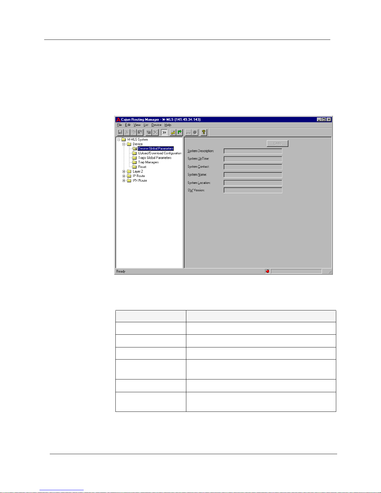
Device Global Parameters
T o display and update global system parameters, click the Device folder and
select
Device Global Parameters. The Device Global Parameters window
appears.
Figure 2-1. Device Global Parameters Window
The following parameters are displayed:
You can edit the System Contact, System Name, and System Location
fields. For more information, refer to Avaya M-MLS Routing Manager User
Interface.
Table 2-1. Global Parameters
Field Name Description
System Description A general description of the device.
System Up Time The time elapsed since the device was reset.
System Contact The name of the person responsible for the device.
System Name The user-assigned name of the device that appears
in the windows describing the device.
System Location The location of the device.
SW Version The software version of the code on the device (i.e.
2.5.7).
Page 15
Avaya M-MLS Routing Manager User Guide 9
Device
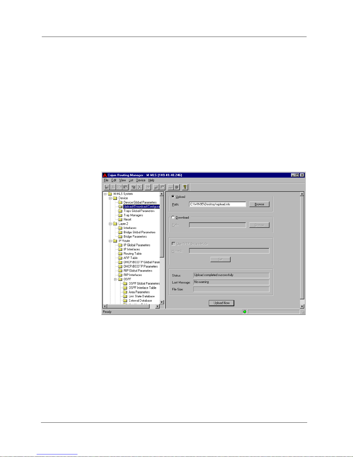
Upload/Download Configuration
The Upload/Download Configuration feature, allows you to save the
configuration of the router in a file, and to download a saved
configuration to the router.
* Note: The Upload/Download Configuration feature uses TFTP.
Ensure that the TFTP server is active before using the
Upload/Download Configuration feature.
To save or download configuration parameters, click the
Device folder and
select
Upload/Download Configuration. The Upload/Download
Configuration window appears.
Figure 2-2. Upload/Download Configuration Window
Selecting TF TP
Secure Mode
(In Solaris
Only)
To limit the access of the TFTP client to a specified path on the disk, you
must configure the TFTP Secure Mode and select a homedir. The TFTP
Secure Mode configuration is required for both uploading and
downloading configuration parameter files. To activate TFTP Secure
Mode:
1. Check the
Use TFTP Secure Mode checkbox.
2. Enter the path of the homedir in the
Homedir field.
3. Click
Set.
Page 16

Chapter 2
10 Avaya M-MLS Routing Manager User Guide
* Note: The TFTP Secure Mode and the Homedir must correspond to
the tftp configuration in the inetd.conf file.
Once TFTP Secure Mode is activated, it remains activated unless the tftp
parameter in the inetd.conf file is modified.
Uploading the
Current
Configuration
to a File
To upload the current configuration to a file:
1. Select the
Upload radio button.
2. In the
Upload - Path field, enter the name and path of the file into
which you would like to save the file containing the current
configuration.
Or
2. Click . A file browser window appears.
a. Select a folder using the browser.
b. Enter a filename into the
File name field.
c. Click
Save. The name of the selected file appears in the Upload -
Path
field.
3. Click
Upload Now. The current configuration is saved in the
specified file.
Downloading
a Saved
Configuration
to the
Router
To download a saved configuration to the router:
1. Select the
Download radio button.
2. In the
Download - Path field, enter the name of the file from which
you would like to download a configuration.
Or
2. Click . A standard file browser window appears.
a. Select a file using the browser.
b. Click
Open. The name of the selected file appears in the
Download - Path field.
3. Click
Download Now. The specified configuration is downloaded to
the router .
Page 17

Avaya M-MLS Routing Manager User Guide 11
Device
Upload/
Download
Configuration
Parameters
In addition, the following parameters are displayed.
Traps Global Parameters
To display and update the global traps parameter, click the Device folder
and select
Traps Global Parameters. The Traps Global Parameters window
appears.
Figure 2-3. Traps Global Parameters Window
Check the
Authentication Traps Status - Enable checkbox to enable
authentication traps globally. When checked, each manager defined in
the Trap Managers window will receive authentication traps. Refer to
“Trap Managers” on page 12.
For more information, refer to Avaya M-MLS Routing Manager User Interface.
Table 2-2. Upload/Download Configuration
Field Name Description
Status The status of the current upload or download
operation.
Last Message Non-fatal warnings issued by the router.
File Size This parameter displays the progress of the file
being downloaded as a percentage of the file’s
total size.
Page 18
Chapter 2
12 Avaya M-MLS Routing Manager User Guide
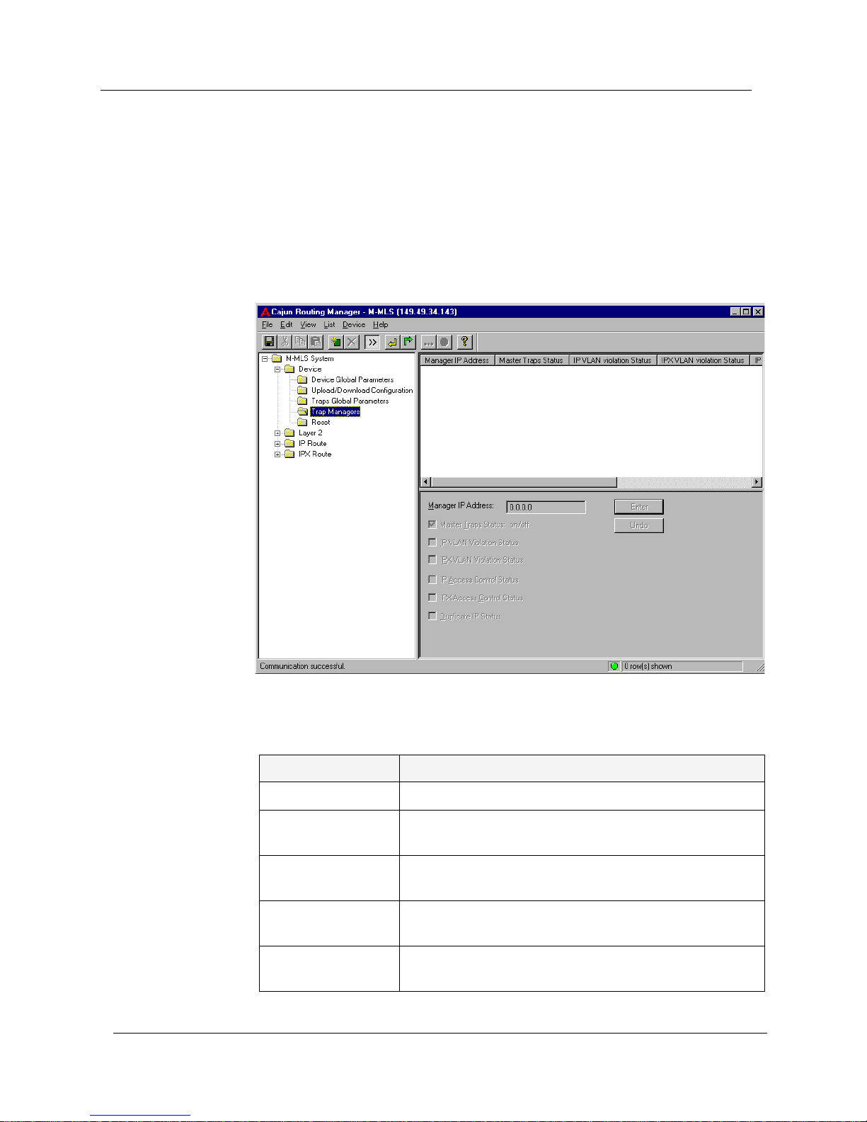
Trap Managers
The Trap Managers window is used to define managers, and select the
traps that specific managers will receive.
To define managers and the traps they receive, click the
Device folder and
select
Trap Managers. The Trap Managers window appears.
Figure 2-4. Trap Managers Window
The following parameters are displayed:
Table 2-3. Trap Managers
Field Name Description
Manager IP Address The IP address of the manager.
Master Traps Status:
on/off
Permit or deny any traps to the manager.
IP VLAN Violation
Status
Permit or deny the IP VLAN Violation trap to the
manager.
IPX VLAN Violation
Status
Permit or deny the IPX VLAN Violation trap to the
manager.
IP Access Control
Status
Permit or deny the IP Access Control trap to the
manager.
Page 19
Avaya M-MLS Routing Manager User Guide 13
Device
* Note: To edit a trap manager’s IP address, you must delete the
manager and add a new one with the correct IP address.
For more information, refer to Avaya M-MLS Routing Manager User Interface.
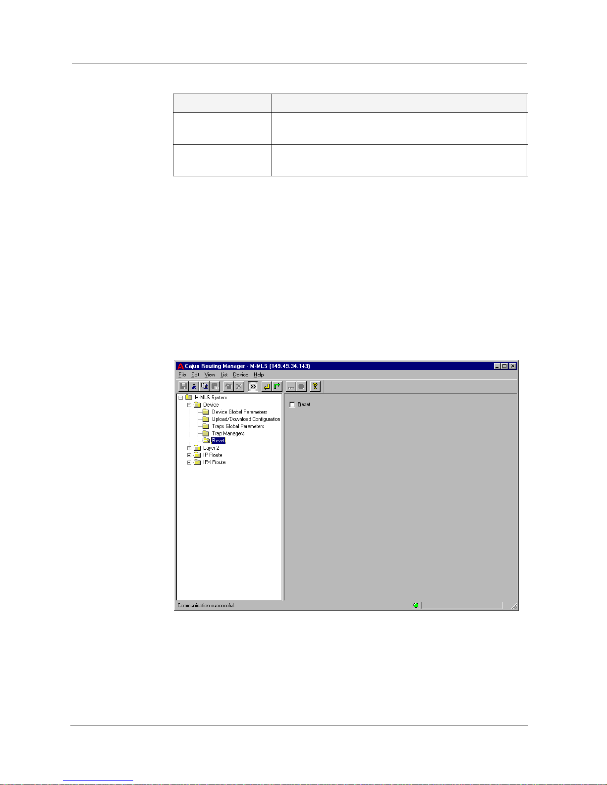
Reset
To reset the router, click the Device folder and select Reset. The Reset
window appears.
Figure 2-5. Reset Window
Check the
Reset checkbox to reset the device. Before the management
station sends the command to reset the device, it requests user
confirmation for this action. After confirmation, the device performs a
complete cold reset of the device.
For more information, refer to Avaya M-MLS Routing Manager User Interface.
IPX Access Control
Status
Permit or deny the IPX Access Control trap to the
manager.
Duplicate IP Status Permit or deny the Warning trap or Duplicate IP trap to
the manager.
Table 2-3. Trap Managers <BlueItalic9>Continued<BlueDingbat9>Ø
Field Name Description
Page 20

Avaya M-MLS Routing Manager User Guide 14
3
Layer 2
The Layer 2 folder provides access to the following windows:
• Interfaces (VLANs)
• Bridge Global Parameters
• Bridge Parameters
Page 21
Avaya M-MLS Routing Manager User Guide 15
Layer 2
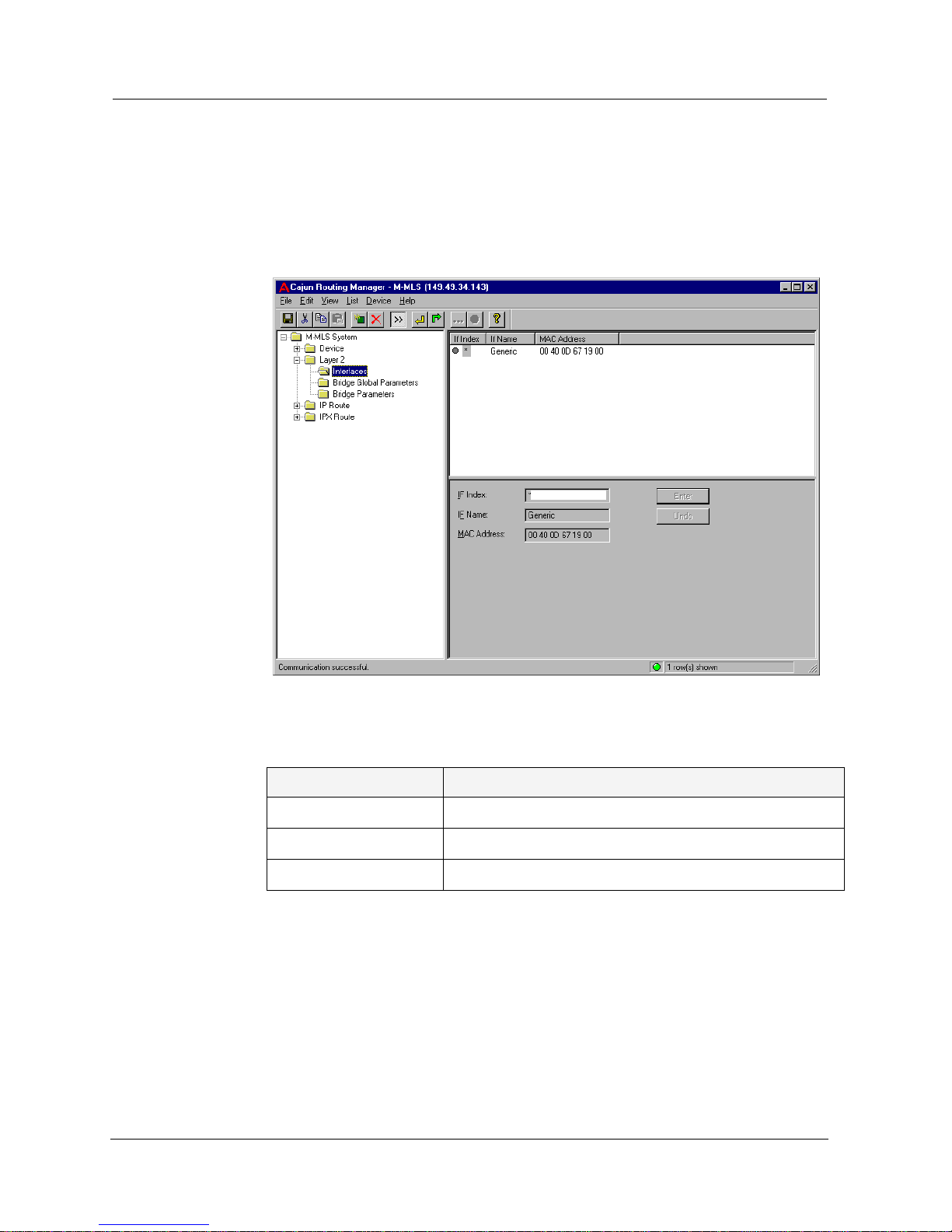
Interfaces (VLANs)
T o define manually or display the layer 2 interfaces, click the Layer 2 folder
and select
Interfaces. The Layer 2 Interfaces window appears.
Figure 3-1. Layer 2 Interfaces Window
The following parameters are displayed:
* Note: It is recommended that you use the station’s predefined
VLANs and create new IP and IPX interfaces on top of the
VLANs.
You can create or delete VLANs. For more information, refer to Avaya M-
MLS Routing Manager User Interface.
* Note: An entry may be deleted only if no IP interface or IPX
interface have been defined on the VLAN interface.
Table 3-1. Layer 2 Interfaces Window Parameters
Field Name Description
If Index The VLAN number of this interface.
If Name The logical name of this interface.
MAC Address The MAC address of this interface.
Page 22
Chapter 3
16 Avaya M-MLS Routing Manager User Guide
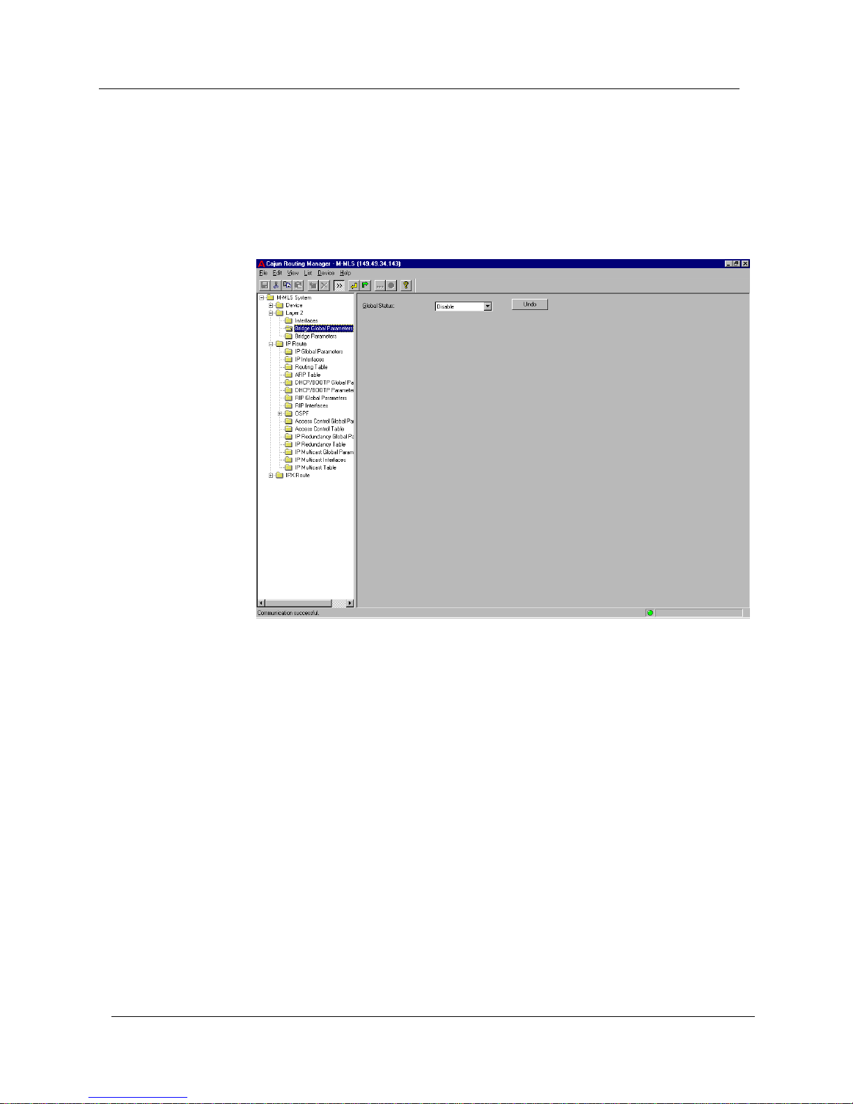
Bridge Global Parameters
To display and update the global bridge parameter, click the Layer 2 folder
and select
Bridge Global Parameters. The Bridge Global Parameters
window appears.
Figure 3-2. Bridge Global Parameters Window
Page 23

Avaya M-MLS Routing Manager User Guide 17
Layer 2
The following parameter is displayed:
For more information, refer to Avaya M-MLS Routing Manager User Interface.
Table 3-2. Bridge Global Window Parameter
Field Name Description
Bridging Status The following Bridging Status values are available:
• Enable - The router will forward broadcast
packets between VLANs.
• Disable - The router will not forward broadcast
packets between VLANs.
• Backup - This mode ties the VLAN Bridging
function to the IP redundancy feature
(configured in the IP Redundancy windows).
With this status, the VLAN Bridging function is
inactive. It will automatically become active in
case of failure of the main router as configured
in the IP Redundancy windows.
• Active Backup - The VLAN Bridging function is
active, as if it was enabled, as long as the main
router (configured in the IP redundancy
window) is not operational. This status value
can not be configured. It is reached
automatically from Backup status upon failure
of the main router, provided that IP
redundancy was configured. When the main
router recovers, the status will return to
Backup.
Page 24
Chapter 3
18 Avaya M-MLS Routing Manager User Guide
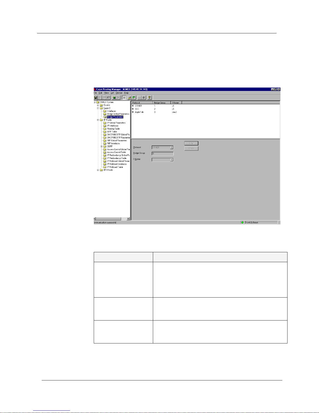
Bridge Parameters
To define bridging protocols, click the Layer 2 folder and select Bridge
Parameters
. The Bridge Parameters window appears.
Figure 3-3. Bridge Parameters Window
The following parameters are displayed:
You can define or remove Bridging pr otocols from the manager. For more
information, refer to Avaya M-MLS Routing Manager User Interface.
Table 3-3. Bridge Parameters Window
Field Name Description
Protocol The user can define Bridging for a particular protocol,
such as NETBIOS, DEC, or AppleTalk. If a particular
protocol is not defined, or if the user i s using a protoco l
that is not supported by the routing manager, then the
user should define the Bridging Protocol as OTHER.
Bridge Group Different configurations of identical protocols are
assigned Bridge Group numbers to maintain unique
identities.
If Name The name of the interface (VLAN). An If Name may not
be used simultaneously by multiple instances of a
protocol. An interface may not be named ‘Generic’.
Page 25

Avaya M-MLS Routing Manager User Guide 19
4
IP Route
The IP Route folder provides access to the following windows:
• IP Global Parameters
• IP Interfaces
•Routing Table
•ARP Table
• DHCP/BOOTP Global Parameters
• DHCP/BOOTP Parameters
• RIP Global Parameters
• RIP Interfaces
• OSPF
• Access Control Global Parameters
• Access Control Table
• IP Redundancy Global Parameters
• IP Redundancy Table
• IP Multicast Global Parameters
• IP Multicast Interfaces
• IP Multicast Table
Page 26

Chapter 4
20 Avaya M-MLS Routing Manager User Guide
IP Global Parameters
To display and update the IP global parameters, click the IP Route folder
and select
IP Global Parameters. The IP Global Parameters window
appears.
Figure 4-1. IP Global Parameters Window
The following parameters are displayed:
Table 4-1. IP Global Parameters
Field Name Description
ICMP Error Messages If enabled, ICMP error messages should be sent. If
disabled, ICMP error messages should not be sent.
ARP Timeout (Sec.) The number of seconds that may pass between ARP
requests concerning entries in the ARP table.
After this period, the entry is deleted from the
table.
Page 27

Avaya M-MLS Routing Manager User Guide 21
IP Route
IP Interfaces
IP interfaces represent the logical connections of the device to the IP nets/
subnets attached to it. Each IP interface corresponds to one net/subnet.
When you create a new IP interface, RIP and OSPF interfaces are
automatically created and assigned enable status. When you delete an IP
interface, the device will delete the associated RIP and OSPF interfaces.
T o define and display the IP interfaces, click the
IP Route folder and select IP
Interfaces
. The IP Interfaces window appears.
Figure 4-2. IP Interfaces Window
The following parameters are displayed:
Table 4-2. IP Interface Parameters
Field Name Description
IP Address The IP address assigned to the device on this
subnet.
IP NetMask The IP network mask of the attached net/subnet.
If Name The name of the Layer 2 interface (VLAN) with
which this subnet is associated. Multiple subnets
may be associated with a single VLAN, so multiple
IP interfaces may be associated with the same If
Name.
Status - Enabled The status of the IP interface. If checked, the IP
interface is enabled.
Page 28

Chapter 4
22 Avaya M-MLS Routing Manager User Guide
You can create, modify and delete IP interfaces. For more information,
refer to Avaya M-MLS Routing Manager User Interface.
* Note: The IP Address, IP NetMask, IF Name and Status must be
defined before creating an IP interface.
* Note: The list of VLANs allocated in the system is displayed in the If
Name field.
Forwarding Broadcast
- Enable
The status of the forwarding of incoming net
directed broadcasts to this interface. If checked, the
forwarding is enabled. If not checked, IP directed
broadcast messages destined to this interface will be
discarded and will not be forwarded to this
interface.
Broadcast Address
- one fill
Determines the format of IP broadcast messages
generated by the device. If checked, the host ID in
the broadcast address is filled with 'one' bits (e.g.
149.49.50.255). Otherwise, the host ID in the
broadcast address is filled with 'zero' bits (e.g.
149.49.50.0).
Proxy ARP - Enable If checked, the device will respond with its own
MAC address to ARP requests for stations th at are
on another VLAN.
Table 4-2. IP Interface Parameters
Field Name Description
Page 29

Avaya M-MLS Routing Manager User Guide 23
IP Route
Routing Table
T o display and update the Routing Table, click the IP Route folder and select
Routing Table. The Routing Table window appears.
Figure 4-3. Routing Table Window
The following parameters are displayed:
Table 4-3. Routing Table Parameters
Field Name Description
Destination The destination network IP address of this route.
An IP address of 0.0.0.0 denotes a default router.
Net Mask The destination network mask of this route.
Next Hop The address of the next router of this route, via
which the destination of this route is reached.
If Name The logical name of the local interface through
which the next hop of this route is reached.
Page 30

Chapter 4
24 Avaya M-MLS Routing Manager User Guide
You can create, modify, or delete Routing Table static entries. For more
information, refer to Avaya M-MLS Routing Manager User Interface.
* Note: Only static entries in the Routing Table can be modified.
Entries learned from OSPF, RIP or local cannot be modified.
Protocol The protocol through which the route was learned.
The following protocols can be specified:
• Static - The route was manually configured to
this device.
• Local - The route represents a directly
attached net/subnet and corresponds to one
of the IP interfaces configured to this device.
• RIP - The entry was learned from the RIP
protocol.
• OSPF - The entry was learned from the OSPF
protocol.
Metric Number of hops to the destination network, or the
cost of the route for OSPF routes.
Route Type The type of route, either local or remote.
Route Age The number of seconds since the route was last
updated.
Table 4-3. Routing Table Parameters
Field Name Description
Page 31

Avaya M-MLS Routing Manager User Guide 25
IP Route
ARP Table
To display and update the ARP Table parameters, click the IP Route folder
and select
ARP Table. The ARP Table window appears.
Figure 4-4. ARP Table Window
The following parameters are displayed:
You can create or delete ARP table entries. For more information, refer to
Avaya M-MLS Routing Manager User Interface.
Table 4-4. ARP Parameters
Field Name Description
IP Address The IP address of the station.
MAC Address The MAC address of the station.
IF Name The name of the interface (VLAN).
Status The status of the interface. Possible status values
are:
• Dynamic - The entry is learned from the ARP
protocol. If the station entry is not active for a
predetermined time, the en try is de leted fro m
the table.
• Static - The entry has been configured by the
network management station and is
permanent.
• Invalid - The entry in the table is invalid.
Page 32

Chapter 4
26 Avaya M-MLS Routing Manager User Guide
DHCP/BOOTP Global Parameters
To display and update the DHCP/BOOTP global parameter, click the IP
Route
folder and select DHCP/BOOTP Global Parameters. The DHCP/BOOTP
Global Parameters window appears.
Figure 4-5. DHCP/BOOTP Global Parameters Window
Page 33

Avaya M-MLS Routing Manager User Guide 27
IP Route
The following parameter is displayed:
To modify the DHCP/BOOTP Global Status, click the pull-down list and
select a status.
Table 4-5. DHCP/BOOTP Global Parameters
Field Name Description
DHCP/BOOTP Global
Status
The following DHCP/BOOTP global status values
are available:
• Enable - Acts according to the DHCP/BOOTP
configuration of each interface.
• Disable - Disables the DHCP/BOOTP relay
over all the interfaces.
• Backup - This mode ties the DHCP/BOOTP
Relay function to the IP redundancy feature
(configured in the IP Redundancy windows).
With this status, the DHCP/BOOTP Relay
function is inactive. It will automatically
become active in case of failure of the main
router as configured in the IP Redundancy
windows.
• Active Backup - The DHCP/BOOTP Relay
function is active, as if it was enabled, as long
as the main router (configured in the IP
redundancy window) is not operational. This
status value can not be configured. It is
reached automatically from Backup status
upon failure of the main router, provided that
IP redundancy was configured. When the
main router recovers, the status will return to
Backup.
Page 34

Chapter 4
28 Avaya M-MLS Routing Manager User Guide
DHCP/BOOTP Parameters
To display and update the DHCP/BOOTP parameters, click the IP Route
folder and select
DHCP/BOOTP Parameters. The DHCP/BOOTP Parameters
window appears.
Figure 4-6. DHCP/BOOTP Parameters Window
The following parameters are displayed:
Table 4-6. DHCP/BOOTP Parameters
Field Name Description
If Name The interface name (VLAN) upon which the clients
are located.
First DHCP Server
Address
The IP address of the first of two possible DHCP
servers for the interface.
Second DHCP Server
Address
The IP address of the second of two possible DHCP
servers for the interface.
Page 35

Avaya M-MLS Routing Manager User Guide 29
IP Route
You can create, modify, or delete DHCP/BOOTP parameters. For more
information, refer to Avaya M-MLS Routing Manager User Interface.
Mode The method by which the DHCP relay chooses an
IP address to include in the DHCP request.
When relaying a DHCP/BOOTP request, the relay
has to write its own IP address into the relayed
DHCP request. This address is used by the DHCP
server to determine the subnet from which the
client’s IP address has been allocated. When the
router has multiple IP ad dresses on the same VLAN,
any of these addresses can be used when relaying
DHCP requests.
The Mode field controls the behavior of the DHCP
relay, in choosing the IP address to write into the
DHCP request. Possible modes are:
• Default - The router chooses one of the
addresses itself. The address chosen will be the
lowest IP address on that VLAN.
• Specific - The router is configured with a
single IP address to be used with all relayed
requests arriving on the VLAN. This address
must be one of the router’s IP addresses on
the specified VLAN. It must be entered in the
IP Address field.
• Duplicate - The router duplicates each
request arriving on the VLAN, and sends
multiple copies of the request to the DHCP
server - one copy for each of the router’ s IP
addresses on the VLAN.
IP Address One of the router’s IP addresses on the VLAN. This
is used for all relayed requests, i f Mode is set to
Specific.
Table 4-6. DHCP/BOOTP Parameters
Field Name Description
Page 36

Chapter 4
30 Avaya M-MLS Routing Manager User Guide
RIP Global Parameters
To display and update RIP global parameters, click the IP Route folder and
select
RIP Global Parameters. The RIP Global Parameters window appears.
Figure 4-7. RIP Global Parameters Window
The following parameters are displayed:
You can modify RIP Global Parameters by checking boxes as desired. For
more information, refer to Avaya M-MLS Routing Manager User Interface.
Table 4-7. RIP Global Parameters
Field Name Description
RIP Global Status Enable
The status of RIP in the device. If checked, the
parameter is enabled, meaning that the RIP process is
active. If the parameter is not checked, the RIP process
is not active on any interface, regardless of the settings
in the RIP Interfaces window.
Leak OSPF into RIP Controls redistribution of routes from OSPF to RIP. If
checked, all routes learned via OSPF are advertised into
RIP.
Leak Static into RIP Controls redistribution of static routes into RIP. If
checked, the static routes inserted into the IP Routing
Table are advertised into RIP, according to the "Leak
Route" definition for each static route.
Page 37

Avaya M-MLS Routing Manager User Guide 31
IP Route
RIP Interfaces
T o define and d isplay the RIP interfaces, click the IP Rout e folder and select
RIP Interfaces
. The RIP Interfaces window appears.
Figure 4-8. RIP Interfaces Window
The following parameters are displayed:
Table 4-8. RIP Interface Parameters
Field Name Description
IP Address The IP address of the interface.
Send Mode What the device sends on this interface. Values are:
• SendAll - RIP updates contain the entire
routing table.
• DoNotSend - No RIP updates are sent.
• SendDefaultOnly - RIP updates contain only
a single entry. This advertises the router as the
default router.
Interface State The operational status of the RIP interface - active
or inactive.
Status - Enable The administrative status of the RIP interface -
enabled or disabled.
Page 38

Chapter 4
32 Avaya M-MLS Routing Manager User Guide
RIP Version The router can be configured to operate either RIP
version 1 or RIP version 2 on each IP interface. The
configuration of the RIP version must be consistent
on each subnet. That is, all routers should be
configured with the same RIP version on their
interface to the subnet.
When possible, homogeneous configuration of the
RIP version in the network is recommended.
RIP1 - The router runs regular RIP on that interface,
following the RIP version 1 subnet aggregation
rules. That is, it advertises an aggregate route for
the net as opposed to advertising subnet routes
across the network boundary.
RIP2 - The router runs RIP version 2 on that
interface. RIP version 2 advertisements are sent as
multicast rather than broadcast. No route
aggregation is done in RIP version 2. RIP version 2
allows for Variable Length Subnets Masks (VLSM),
meaning that subnets of the same net may have
masks of different lengths, and may be of different
sizes.
Interface Cost The cost of using this interface. RIP chooses the
route with the lowest total cost (metric) for each
destination.
Default Route Metric The metric of the default route entry in RIP updates
originated on this interface, if configured to
"Default Route Only".
Accept Default Whether to accept default route entries in RIP
messages received from other routes on this
interface.
Split Horizon The method for handling routes learned from this
interface, when sending updates to this interface.
Possible methods are:
• Poisoned Reverse - The routes are advertised
to this interface as unreachable.
• Split Horizon - The routes are not advertised
to this interface at all.
• None - The routes are advertised to this
interface as is.
Authentication Type Authentication Method. Possible methods are:
• None
• Simple
Table 4-8. RIP Interface Parameters
Field Name Description
Page 39

Avaya M-MLS Routing Manager User Guide 33
IP Route
* Note: In the Send field, selecting ‘DoNotSend’ or ‘SendAll’ will
prevent updating the Default Route Metric field.
You can modify the RIP interfaces. For more information, refer to Avaya
M-MLS Routing Manager User Interface.
OSPF
The OSPF folder provides access to the following windows:
• OSPF Global Parameters
• OSPF Interface Table
• OSPF Area Parameters
• OSPF Link State Database
• OSPF External Database
• OSPF Neighbor Table
Authentication Key The password for this interface. This is only used if
the Authentication Type is set to Simple-password.
The password may contain up to 16 characters. It
may be configured here, but not viewed.
Table 4-8. RIP Interface Parameters
Field Name Description
Page 40

Chapter 4
34 Avaya M-MLS Routing Manager User Guide
OSPF Global Parameters
To define and display OSPF Global parameters, click the IP Route folder,
click the
OSPF folder, and select OSPF Global Parameters. The OSPF Global
Parameters window appears.
Figure 4-9. OSPF Global Parameters Window
The following parameters are displayed:
Table 4-9. OSPF Global Parameters
Field Name Description
OSPF Router ID The ID number of the router. The router ID must be
unique. By default, the router ID equals one of the
router IP addresses.
OSPF Global Status Enabled
The administrative status of OSPF in the router. If not
checked, OSPF is not active on any interface, regardless
of the settings in the OSPF Interfaces window.
Leak RIP into OSPF Controls redistribution of routes from RIP to OSPF. If
checked, all routes learned via RIP are advertised into
OSPF as external routes.
Leak Static into OSPF Controls redistribution of static routes into OSPF. If
checked, routes are advertised into OSPF as external
routes, according to the "Leak Route" definition for
each static route.
Leak Direct into OSPF Controls redistribution of direct routes which are
external to OSPF. If checked, local subnets on which
OSPF is disabled are advertised into OSPF as external
routes.
Page 41

Avaya M-MLS Routing Manager User Guide 35
IP Route
You can modify OSPF Global Parameters. For more information, refer to
Avaya M-MLS Routing Manager User Interface.
* Note: After updating the Router ID field, a message is displayed
warning that the operation might cause the OSPF database to
reset.
OSPF Interface Table
To define and display the OSPF interfaces, click the IP Route folder, click
the
OSPF folder, and select OSPF Interface Table. The OSPF Interface Table
window appears.
Figure 4-10. OSPF Interface Table Window
The following parameters are displayed:
Table 4-10. OSPF Interface Parameters
Field Name Description
IP Address The IP address of this OSPF interface.
Designated Router The IP Address of the designated router.
Backup Designated
Router
The IP Address of the backup designated router.
Page 42

Chapter 4
36 Avaya M-MLS Routing Manager User Guide
You can modify OSPF interfaces. For more information, refer to Avaya MMLS Routing Manager User Interface.
Interface State The interface state of the OSPF interface:
• Down - OSPF is not active on the interface.
• Waiting - The identity of the designated router
for this subnet is not determined yet.
• Designated Router - The router is the Designated
Router on this subnet.
• Backup Designated Router - This router is the
Backup Designated Router.
• Other Designated Router - Another router is the
Designated Router on this subnet.
Status - Enabled If checked, this denotes that the interface may form
neighbor relationships, and that the interface is
advertised as an internal route to OSPF. If not checked,
the interface is external to OSPF.
Priority The priority of this router to become the designated
router on this interface. A value of zero indicates that
this router is not eligible to become the designated
router on the current network. If more than one router
has the same priority, then the router ID is used.
Hello Interval The period of time (in seconds) betw een Hell o pack ets.
All routers attached to a common network must have
the same Hello Interval.
Dead Interval The period of time (in seconds) that a router’s Hello
packets have not been seen before the router’s
neighbors declare the router is down. All routers
attached to a common network must have the same
Dead interval.
Interface Cost The cost of using this interface. OSPF will choose the
route with the lowest total cost (metric) to each
destination.
Authentication Type Authentication Method. Possible methods are:
• None
• Simple
Authentication Key The password for this interface. This is only used if the
Authentication Type is set to Simple-password. The
password may contain up to 8 characters. It may be
configured here, but not viewed.
Table 4-10. OSPF Interface Parameters
Field Name Description
Page 43

Avaya M-MLS Routing Manager User Guide 37
IP Route
OSPF Area Parameters
To define and display the OSPF Area Parameters, click the IP Route folder,
click the
OSPF folder, and select Area Parameters. The OSPF Area
Parameters window appears.
Figure 4-11. OSPF Area Parameters Window
The following parameters are displayed:
Table 4-11. OSPF Area Parameters
Field Name Description
Area ID A unique number identifying the OSPF area to
which this router belongs. Area ID 0.0.0.0 is used
for the OSPF backbone.
Stub Area If checked, external link-state advertisements are
not imported into the area.
Area Border Routers
Count
The total number of Area Border Routers reachable
within this area. This number is initially zero and is
calculated in each SPF pass.
AS Border Routers
Count
The total number of Autonomous System border
routers reachable within this area. This number is
initially zero and is calculated in each SPF pass.
Area LSAs Count The number of link-state advertisements in the
link-state database.
Page 44

Chapter 4
38 Avaya M-MLS Routing Manager User Guide
You can modify OSPF parameters. For more information, refer to Avaya
M-MLS Routing Manager User Interface.
OSPF Link State Database
T o display the OSPF L ink State Database, click the IP Route folder, click the
OSPF folder, and select Link State Database. The OSPF Link State Database
window appears.
Figure 4-12. OSPF Link State Database Window
The following parameters are displayed:
Area LS Checksum
Summary
The sum of LS checksums of LS advertisements
contained in the LS database. Use this sum to
determine if there has been a change in a router’s
LS database, and to compare the LS database of two
routers.
Table 4-11. OSPF Area Parameters
Field Name Description
Table 4-12. OSPF Link State Database Window
Field Name Description
LSA Type The type and format of the link state
advertisement; for example, Router links and
Network links.
Page 45

Avaya M-MLS Routing Manager User Guide 39
IP Route
The parameters in the OSPF Link State Database window are read-only.
LSA ID Identifies the part of the routing domain that is
described by the advertisement. The LSA ID can be
either a router ID or an IP address.
Router ID Identifies the originating router in the autonomous
system.
Sequence Number The sequence number of the link state
advertisement. Use this parameter to detect old and
duplicate link state advertisements. The larger the
sequence number, the more recent the
advertisement. Note that the sequence number is
usually negative.
LSA Age The age of the link state advertisement (in
seconds).
Checksum This parameter is a checksum of the complete
contents of the advertisement, not including the
Age value.
Table 4-12. OSPF Link State Database Window
Field Name Description
Page 46

Chapter 4
40 Avaya M-MLS Routing Manager User Guide
OSPF External Database
To display the OSPF External Database window, click the IP Ro ute folder,
click the
OSPF folder, and select External Database. The OSPF External
Database window appears.
Figure 4-13. OSPF External Database Window
The following parameters are displayed:
Table 4-13. OSPF External Database Window
Field Name Description
LSA Type The type and format of the link state
advertisement; for example, Router links and
Network links.
LSA ID Identifies the part of the routing domain that is
described by the advertisement. The LSA ID can be
either a router ID or an IP address.
Router ID Identifies the originating router in the autonomous
system.
Sequence Number The sequence number of the link state
advertisement. Use this parameter to detect old and
duplicate link state advertisements. The larger the
sequence number, the more recent the
advertisement. Note that the sequence number is
usually negative.
Page 47

Avaya M-MLS Routing Manager User Guide 41
IP Route
The parameters in the OSPF External Database window are read-only.
OSPF Neighbor Table
To display the OSPF Neighbors Table, click the IP Route folder, click the
OSPF folder, and select Neighbor Table. The OSPF Neighbor Table window
appears.
Figure 4-14. OSPF Neighbors Table Window
The following parameters are displayed:
LSA Age The age of the link state advertisement (in
seconds).
Checksum This parameter is a checksum of the complete
contents of the advertisement, not including the
Age value.
Table 4-13. OSPF External Database Window
Field Name Description
Table 4-14. OSPF Neighbors Parameters
Field Name Description
Neighbor Address The IP address of this neighbor.
Router ID The unique OSPF identifier for the neighboring
router.
Page 48

Chapter 4
42 Avaya M-MLS Routing Manager User Guide
The parameters in the OSPF Neighbors Table window are read-only.
Neighbor State The state of the relationship with this neighbor:
• Down
• Attempt
• Init
• Two Way
• Exchange Start
• Exchange
• Loading
• Full
Priority The priority of this neighbor in the Designated
Router election.
Retransmit QLength The current length of the retransmission queue.
Table 4-14. OSPF Neighbors Parameters
Field Name Description
Page 49

Avaya M-MLS Routing Manager User Guide 43
IP Route
Access Control Global Parameters
To define and display the Access Control global parameter, click the IP
Route
folder and select Access Control Global Parameters. The Access
Control Global Parameters window appears.
Figure 4-15. Access Control Global Parameters Window
The following parameter is displayed:
To enable the Access Control Global Status, click the checkbox. The
Access Control global parameter applies to all entries in the Access
Control table. For more information, refer to Avaya M-MLS Routing
Manager User Interface.
Table 4-15. Access Control Global Parameter
Field Name Description
Access Control Global
Status
Enables or disables IP Access Control as configured
in the Access Control table.
Page 50

Chapter 4
44 Avaya M-MLS Routing Manager User Guide
Access Control Table
The device provides sophisticated hardware-based access control packet
filtering of forwarded IP traffic. The user can specify whether to forward,
block, or block and report packets of specific types by configuration of
access control statements. IP access control statements can specify source
and destination IP address ranges, as well as the application type.
The IP address ranges are defined by an IP address and mask (wild-card),
and can specify a single IP station, a subnet or net, or all IP stations. An
example of a simple access control statement would be that IP stations of
the net 150.5.0.0 can not communicate to station 193.1.1.1. More
advanced access control statements can specify the protocol above IP (e.g.
TCP, UDP) and specific applications (UDP/TCP port numbers), e.g. HTTP
or Telnet. The device will check the TCP/UDP destination port against
configured applications.
The access control filtering rules can be asymmetric, allowing certain
traffic in one direction while blocking the same application in the opposite
direction, based on which side initiates the session. In order to allow a
certain application, when the default is block, the access control
statements must explicitly allow for both the packets in one direction (e.g.
requests) and the packets in the other direction (e.g. replies).
Packets in the first direction usually have the application’s well-known
port number in the TCP destination port, but the replies usually use
dynamic port numbers in the destination port. For that purpose, all
replies can be allowed in that direction by configuring an access control
statement in the device with port number >1023. This statement means
"forward all the packets, from these source addresses to those destination
addresses, whose destination port number is above 1023". When the TCP
port >1023, the device will also check that the TCP ACK bit is set. This
additional check protects against attacks via protocols using high-number
ports, by guaranteeing that the packet is not an initiation of a new session
- the packet is part of an established session that was previously initiated
from the other direction and allowed by the device.
Page 51

Avaya M-MLS Routing Manager User Guide 45
IP Route
To display and update the Access Control Table, click the IP Route folder
and select
Access Control Table. The Access Control T able window appears.
Figure 4-16. Access Control Table Window
The following parameters are displayed:
Table 4-16. Access Control Table Window
Field Name Description
Source Address The source address of the traffic.
Source Mask The mask defining a range of addresses by setting
how many bits of the source address are relevant.
Destination Address The destination address of the traffic.
Destination Mask The mask defining a range of addresses by setting
how many bits of the destination address are
relevant.
Protocol Select the protocol (All, ICMP, UDP, TCP) to filter.
Application This field applies if the Protocol is UP or TCP. The
user can select one of the predefined ports or add a
user-defined value by typing its number. Only 10
user-defined ports are allowed.
Page 52

Chapter 4
46 Avaya M-MLS Routing Manager User Guide
You can create or delete entries in the Access Control table. For more
information, refer to Avaya M-MLS Routing Manager User Interface.
IP Redundancy Global Parameters
To define and display Redundancy Global Parameters, click the IP Route
folder and select
IP Redundancy Global Parameters. The Redundancy
Global Parameters window appears.
Figure 4-17. IP Redundancy Global Parameters Window
Operation Whether the indicated traffic is allowed access or
not:
• Forward - Traffic is allo wed access.
• Block - Traffic is not allowed access.
• Block and Report - Traffic is not allowed
access, and an SNMP trap is sent containing
the source address of the traffic and the Entry
ID.
Table 4-16. Access Control Table Window
Field Name Description
Page 53

Avaya M-MLS Routing Manager User Guide 47
IP Route
The following parameters are displayed:
You can modify the IP Redundancy Global Parameters. For more
information, refer to Avaya M-MLS Routing Manager User Interface.
Table 4-17. Redundancy Global Parameters
Field Name Description
Redundancy Status Enable
The entry status:
• Enable - Enables IP Redundancy as
configured in the IP Redundancy Table
window.
• Disable - Disables the IP Redundancy
function.
Redundancy State
Active
When the IP Redundancy Status is enable d, the
state of the backup router may be inactive or active.
• Inactive - No special function is performed by
the secondary router except polling the main
router. While the main router is operational,
the Redundancy State remains inactive.
• Active - The backup router detected the
failure of the main router and is currently
forwarding traffic in its place. It answers ARP
requests for the main router, providing its
own MAC address. While the Redundancy
State is active, the backup router continues to
poll the main router to check for recovery.
Redundancy TimeOut The interval in seconds during which the main
router must signal. If the main router does not
signal within this interval, it is considered not
operational.
Redundancy Polling
Interval
The polling interval for this router, in seconds. If
the interval is zero, then the router is not polled.
Page 54

Chapter 4
48 Avaya M-MLS Routing Manager User Guide
IP Redundancy Table
To define and display IP Redundancy parameters, click the IP Route folder
and select
IP Redundancy Table. The IP Redundancy Table window
appears.
In order for this device to back up the main router, the IP addresses of the
main router must be configured in this window. This window contains an
entry for each of the device’s IP interfaces. The corresponding IP address
of the main router must be configured in each entry that represents a
subnet common to this device and the main router. Entries cannot be
deleted or added. Entries that do not specify an IP address of the main
router do not participate in the redundancy function.
Figure 4-18. IP Redundancy Parameters Window
The following parameters are displayed:
You can modify IP Redundancy parameters.
Table 4-18. Redundancy Parameters
Field Name Description
IP Address The IP addresses of this device identifying the IP
interface.
Main Router Address The IP address of the main router to be polled and
backed up. 0.0.0.0 denotes that the redundancy
feature does not operate on this interface.
Page 55

Avaya M-MLS Routing Manager User Guide 49
IP Route
IP Multicast Global Parameters
To define and display the IP Multicast global parameters, click the IP Route
folder and select
IP Multicast Global Parameters. The IP Multicast Global
Parameters window appears.
Figure 4-19. IP Multicast Global Parameters Window
Page 56

Chapter 4
50 Avaya M-MLS Routing Manager User Guide
The following parameter is displayed:
You can modify the IP Multica st Global Parameter. For more information,
refer to Avaya M-MLS Routing Manager User Interface.
Table 4-19. IP Multicast Global Parameter
Field Name Description
IP Multicast Status Enable
The following IP Multicast Status global status
values are available:
• Enable - The router will forward IP multicast
packets between interfaces, based on
dynamically learned as well as configured
information. Multicast packets to be
forwarded are those whose destination is a
Class D address. Packets with a local
destination IP address, i.e. address of the form
224.0.0.X, are not forwarded.
• Disable - The router will not forward IP
multicast packets between interfaces.
• Backup - This mode ties the IP Multicast
function to the IP redundancy feature
(configured in the IP Redundancy windows).
With this status, the IP Multicast function is
inactive. It will automatically become active
in case of failure of the main router as
configured in the IP Redundancy windows.
• Active Backup - The IP Multicast function is
active, as if it was enabled, as long as the main
router (configured in the IP redundancy
window) is not operational. This status value
can not be configured. It is reached
automatically from Backup status upon
failure of the main router, provided that IP
redundancy was configured. When the main
router recovers, the status will return to
Backup.
Page 57

Avaya M-MLS Routing Manager User Guide 51
IP Route
IP Multicast Interfaces
To define and display IP Multicast Interfaces, click the IP Route folder and
select
IP Multicast Interfaces. The IP Multicast Interfaces window appears.
Figure 4-20. IP Multicast Interfaces Window
The following parameters are displayed:
Table 4-20. IP Multicast Interfaces
Field Name Description
If Name The name of the interface. An interface may not be
named ‘Generic’.
IP Multicast Status When checked, IP multicast forwarding is enabled
on this interface.
When not checked, IP multicast forwarding is
disabled on this interface. This means that IP
multicast packets arriving from this interface will
not be forwarded at all. IP multicast packets from
other interfaces will not be forwarded to th is
interface by the router. IGMP will not operate on
this interface.
IP Multicast State When checked, IP multicast forwarding is activeon
this interface.
When not checked, IP multicast forwarding is not
active on this interface.
Page 58

Chapter 4
52 Avaya M-MLS Routing Manager User Guide
You can modify the IP Multicast Interfaces parameters. For more
information, refer to Avaya M-MLS Routing Manager User Interface.
IP Multicast Table
The Multicast Table shows which multicast groups have members on
which interfaces. This table determines how the router performs
forwarding of IP multicast packets. If the destination IP address of a packet
is an IP multicast group found in the Multicast Table, then this packet is
forwarded to all interfaces associated with that multicast group. The
packet may be forwarded to additional interfaces configured to ‘IP
Multicast Send All’. If the multicast destination address is not found in the
IP Multicast Table, then the packet is only forwarded to those interfaces
configured to ‘IP Multicast Send All’, or discarded if there are no such
interfaces.
IP Multicast Send All When checked, this interface will receive a copy of
every forwarded multicast packet, regardless of
IGMP.
When not checked, this interface may or may not
receive packets of certain multicast groups, as
learned dynamically by IGMP.
IGMP Status When checked, the router operates IGMP on this
interface. IGMP will dynamically learn which
multicast groups have members on this interface.
IGMP Version The version of IGMP running on this interface.
IGMP Query Interval The frequency at which IGMP query packets are
transmitted on this interface.
IGMP Querier The address of the IGMP Querier on the IP subnet
to which this interface is attached.
IGMP Query Response
Time
The maximum query response time advertised in
IGMPv2 queries on this interface.
Table 4-20. IP Multicast Interfaces
Field Name Description
Page 59

Avaya M-MLS Routing Manager User Guide 53
IP Route
To display the IP Multicast Table, click the IP Route folder and select IP
Multicast Table
. The IP Multicast Table appears.
Figure 4-21. IP Multicast Table
The following parameters are displayed:
The IP Multicast Table can be sorted by multicast group to show all
interfaces associated with that group, or can be sorted by interface to
show all multicast groups that have members on that interface.
To sort the IP Multicast Table, click on a column heading to sort by that
column.
For more information, refer to Avaya M-MLS Routing Manager User Interface.
Table 4-21. IP Multicast Table
Field Name Description
IP Multicast Group The name of an IP Multicast Group.
If Name The name of the interface.
Page 60

Avaya M-MLS Routing Manager User Guide 54
5
IPX Route
IPX Route enables you to display and update the following windows:
• IPX Interfaces
• RIP Interfaces
• RIP Routing Table
• SAP Interfaces
• SAP Services
• SAP Filters Global Parameters
• SAP Filters
• Access Control Global Parameters
• Access Control Table
Page 61

Avaya M-MLS Routing Manager User Guide 55
IPX Route
IPX Interfaces
The IPX Interfaces window enables you to display, create, modify and
delete IPX interfaces. Adding new IPX interfaces automatically generates
RIP and SAP interfaces.
To define and display the IPX interfaces, click the
IPX Route folder and
select
IPX Interfaces. The IPX Interfaces window appears.
Figure 5-1. IPX Interfaces Window
The following parameters are displayed:
Table 5-1. IPX Interfaces Parameters
Field Name Description
Circuit No The IPX circuit number specific to the IPX interface
automatically assigned to the device.
Network No The IPX network address.
If Name The name of the Layer 2 interface.
Page 62

Chapter 5
56 Avaya M-MLS Routing Manager User Guide
* Note: The Network No, Encapsulation, and If Name must be defined
before creating an IPX interface.
* Note: For a specific encapsulation, only one network number can be
configured per If Name.
You can create, modify, or delete IPX interfaces. For more information,
refer to Avaya M-MLS Routing Manager User Interface.
Encapsulation Encapsulation method associated with this IPX
interface. The encapsulation types are:
• Raw
• Ethernet
• IIc
• Snap
Status - Enable Whether this interface entry is enabled or disabled.
Netbios Delivery -
Enable
Enable Netbios type 20 broadcast frames to be
forwarded via this interface.
Table 5-1. IPX Interfaces Parameters
Field Name Description
Page 63

Avaya M-MLS Routing Manager User Guide 57
IPX Route
RIP Interfaces
To display and update the RIP Interfaces, click the IPX Route folder and
select
RIP Interfaces. The RIP Interfaces window appears.
The RIP interface is created automatically when you create a new IPX
interface; deleting the IPX interface will also delete the RIP interface.
Figure 5-2. RIP Interfaces Window
The following parameters are displayed:
Table 5-2. RIP Interface Parameters
Field Name Description
Circuit No The IPX circuit number specific to the RIP interface.
Network No The IPX network that RIP messages are accepted
and sent from.
Status - Enable The status of the RIP interface. If checked, the RIP
interface is enabled.
State - Active The state of the RIP interface. If the RIP status is
enabled but the IPX Interface is disabled, the IPX
RIP interface state will be inactive.
Update Interval The RIP Periodic update interval, in seconds.
Page 64

Chapter 5
58 Avaya M-MLS Routing Manager User Guide
You can modify RIP interface parameters. For more information, refer to
Avaya M-MLS Routing Manager User Interface.
RIP Routing Table
The IPX RIP routing table contains the best route to the destination
networks that can be reached by the IPX router.
To display the RIP routing table, click the
IPX Route folder and select RIP
Routing Table
. The RIP Routing Table appears.
Figure 5-3. RIP Routing Table
The following parameters are displayed:
Aging Time The holding time for information received in RIP
periodic updates. This value defines how many
seconds RIP information remains without being
refreshed.
Table 5-2. RIP Interface Parameters
Field Name Description
Table 5-3. RIP Routing Table Parameters
Field Name Description
Destination NetNumber Destination IPX network numbers in ascending
order.
Next Hop NetNumber IPX network number of the next hop.
Page 65

Avaya M-MLS Routing Manager User Guide 59
IPX Route
* Note:
Static Route is not allowed.
The parameters in the IPX RIP Routing Table window are read-only.
Next Hop Address IPX node address (12 hexadecimal digits) of the
next IPX router in the route to the destination
network that is described by this table entry. If the
destination network is one of the network
segments directly connected to this IPX router, this
field contains all zeroes.
Protocol The routing protocol from which knowledge of this
destination NetNumber was obtained:
• Local - The entry was learned from the
parameters of the current router.
• RIP - The entry was learned from the RIP
protocol.
Ticks to Network An estimate of the time required for the
propagation of a packet sent along the route
described by this table entry to the destination
network. This estimate is given in ticks (there are
18.21 ticks in a second), and does not include
delays introduced by buffers used for tempo ra ry
storage of packets in routers.
Hops to Network Number of hops on the route to the destination
network described by this table entry.
Next Hop Circuit No. The IPX circuit that is used to get to the next hop
router for a remote network.
Age Time in seconds from the last RIP update needed to
remove a service learned from RIP.
Table 5-3. RIP Routing Table Parameters
Field Name Description
Page 66
Chapter 5
60 Avaya M-MLS Routing Manager User Guide
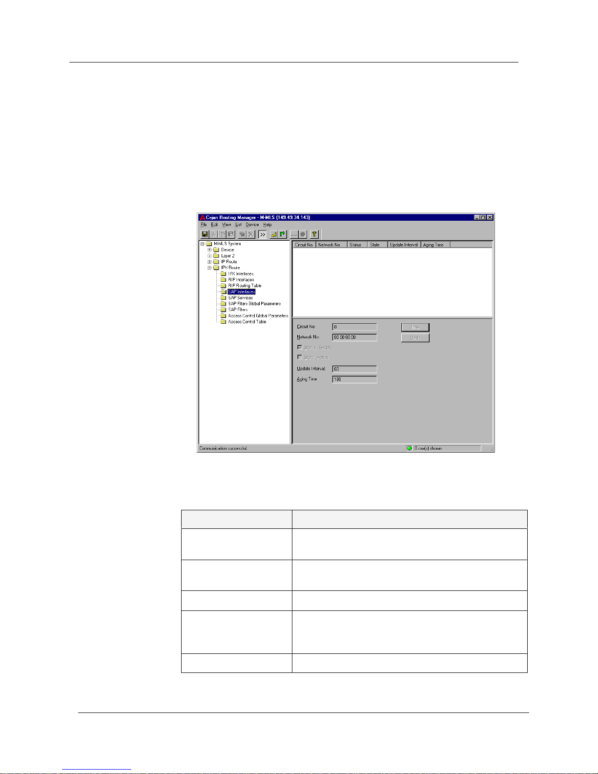
SAP Interfaces
To display and update the SAP Interfaces, click the IPX Route folder and
select
SAP Interfaces. The SAP Interfaces window appears.
The SAP interface is created automatically when you create a new IPX
interface; deleting the IPX interface will also delete the SAP interface.
Figure 5-4. SAP Interfaces Window
The following parameters are displayed:
Table 5-4. SAP Interface Parameters
Field Name Description
Circuit No The IPX circuit number specific to the SAP
interface.
Network No The IPX network from which the SAP interface
accepts and sends SAP messages.
Status - Enable The status of the SAP interface.
State - Active The state of the SAP interface. If the SAP status is
enabled but the IPX Interface is disabled, the IPX
SAP interface state will be inactive.
Update Interval The SAP periodic update interval, in seconds.
Page 67

Avaya M-MLS Routing Manager User Guide 61
IPX Route
You can modify SAP interface parameters. For more information, refer to
Avaya M-MLS Routing Manager User Interface.
SAP Services
The SAP Services window contains information about each service,
located on every server in the network that can be reached by the IPX
router.
To display SAP services, click the
IPX Route folder and select SAP Services.
The SAP Services window appears.
Figure 5-5. SAP Services Window
The following parameters are displayed:
Aging Time The holding time for information received in SAP
periodic updates. This value defines how many
seconds SAP information remains without being
refreshed.
Table 5-4. SAP Interface Parameters
Field Name Description
Table 5-5. SAP Services Parameters
Field Name Description
Service Type Type of service (assigned by Novell) provided by the
server.
Page 68

Chapter 5
62 Avaya M-MLS Routing Manager User Guide
The parameters in the SAP services window are read-only.
Service Name Service type and server name, uniquely defining a
server. The name can be up to 48 characters in length.
Server Net Address Network portion (4 hexadecimal digits) of the IPX
network address.
Server Node Address Node portion of the IPX server address.
Server Socket Address Socket portion of the IPX server address.
Protocol The protocol from which knowledge of this service was
obtained.
Hops to Server Number of h ops o n the r oute to the server, determined
by the IPX SAP routing algorithm.
Age Time in seconds from the last SAP update needed to
remove a service learned from SAP.
Table 5-5. SAP Services Parameters
Field Name Description
Page 69

Avaya M-MLS Routing Manager User Guide 63
IPX Route
SAP Filters Global Parameters
T o display and update the SAP Filters Global parameter, click the IPX Route
folder and select
SAP Filters Global Parameters. The SAP Filters Global
Parameters window appears.
Figure 5-6. SAP Filters Global Parameters Window
The following parameter is displayed:
To enable the SAP Filter Global Status, click the checkbox. For more
information, refer to Avaya M-MLS Routing Manager User Interface.
* Note: If the SAP Filter Global Status is disabled, you can still modify
the SAP Filter parameters.
Table 5-6. SAP Global Filters Parameter
Field Name Description
SAP Filters Global
Status - Enable
Enables or disables all SAP Filters as configured in
the SAP Filters Parameters window.
Page 70

Chapter 5
64 Avaya M-MLS Routing Manager User Guide
SAP Filters
To display and update the SAP Filters, click the IPX Route folder and select
SAP Filters Parameters. The SAP Filters Parameters window with the list of
interfaces appears.
Figure 5-7. SAP Filters Parameters Window
The following parameters are displayed:
Table 5-7. SAP Filters Parameters
Field Name Description
Circuit No The IPX circuit number specific to the device.
Network No The network from which SAP messages are sent or
received. An * (asterisk) represents all networks.
Server Name The name of the server. An * (asterisk) represents
all servers.
Service Type Type of service (assigned by Novell) provided by the
server. An * (asterisk) represents all service types.
Direction The direction that SAP messages should be allowed
from:
• Input
• Output
Page 71

Avaya M-MLS Routing Manager User Guide 65
IPX Route
* Note:
The Circuit No, Direction, and Operation must be defined
before creating a SAP Filter.
You can create or delete SAP Filte rs. For more inform ation, r efer to Avaya
M-MLS Routing Manager User Interface.
Access Control Global Parameters
The Access Control Global Parameters window contains a global
parameter that enables or disables all entries in the Access Control Table.
To display and update the Access Control Global parameter, click the
IPX
Route
folder and select Access Control Global Parameters. The Access
Control Global Parameters window appears.
Figure 5-8. Access Control Global Parameters Window
Operation Permit Whether to permit or deny sending SAP messages
that are configured for this entry.
Table 5-7. SAP Filters Parameters
Field Name Description
Page 72

Chapter 5
66 Avaya M-MLS Routing Manager User Guide
The following parameter is displayed:
To enable the Access Control Global Status, click the checkbox. For more
information, refer to Avaya M-MLS Routing Manager User Interface.
Table 5-8. Access Control Global Parameters
Field Name Description
Access Control Global
Status - Enabled
Enables or disables all entries in the Access Control
Table.
Page 73

Avaya M-MLS Routing Manager User Guide 67
IPX Route
Access Control Table
The device provides sophisticated hardware-based access control packet
filtering of forwarded IPX traffic. Users can specify whether to forward,
block, or block and report packets of specific types, by configuration of
access control statements. IPX access control is based on IPX network
numbers.
To display and update the Access Control Table, click the
IPX Route folder
and select
Access Control Table. The Access Control Table appears.
Figure 5-9. Access Control Table
The following parameters are displayed:
Table 5-9. Access Control Table Parameters
Field Name Description
Source Address The source address of the traffic. An * (asterisk)
appears when all of the addresses are defined.
Destination Address The destination address of the traffic. An *
(asterisk) appears when all of the addresses are
defined.
Page 74

Chapter 5
68 Avaya M-MLS Routing Manager User Guide
* Note: The Source Address, Destination Address, and Operation must
be defined before creating an Access Control Table entry.
You can create, modify, or delete Access Control Table entries. For more
information, refer to Avaya M-MLS Routing Manager User Interface.
Operation Whether the indicated traffic is allowed access or
not:
• Forward - Traffic is allowed.
• Block - Traffic is not allowed.
• Block and Report - Traffic is not allowed
access, and an SNMP trap is sent containing
the source address of the traffic.
Table 5-9. Access Control Table Parameters
Field Name Description
Page 75

Avaya M-MLS Routing Manager User Guide 69
A
Error Messages
This section provides detailed error messages for the Router Manager.
These include Router Manager error messages and SNMP error
messages.
Router Manager Error Messages
The following is a table of Avaya M-MLS Routing Manager error
messages with explanations. An ‘X’ represents text that changes,
depending on the context.
Table A-1. Error Messages and Explanations
Error Message Explanation
Do you want to update the
router with your changes?
Displayed when an attempt is made to leave the
current screen while there are new or updated
entries that were not sent to the device. The
user can choose to update the device with the
changes, to discard the changes, or to cancel the
operation and not leave the screen.
Next Hop already exists at
X. It will be replaced by X.
Displayed when an existing entry in the routing
table is edited, and the next hop value is
changed.
You are about to update
enabled interfaces. This
may have side effects.
Displayed when the user attempts to update an
enabled interface in a way that may cause side
effects, such as disconnecting some part of the
network.
Please enter a valid integer. Displayed when an invalid entry is entered in a
field that expects an integer. This message only
appears when the Enter button is pressed.
Please enter an integer
between X and X.
Displayed when an out of bound integer is
entered for a field that expects a value in the
range X to X.
You may not change to
this value.
Displayed when a user selects a value in a field
or checkbox that should not be changed.
Page 76

Appendix A
70 Avaya M-MLS Routing Manager User Guide
This operation might cause
an OSPF Database Reset.
Press ‘Yes’ to continue.
Press ‘No’ to discard your
changes. Press ‘Cancel’ to
cancel the operation.
Displayed when the user changes the OSPF
global status to disable, or changes the OSPF
Router ID.
Some mandatory
parameters were not
entered.
Displayed to notify the user that required fields
for this window have not been filled. The cursor
is usually positioned at the next required field.
Please enter a valid Net
Number.
Displayed when an invalid net number is
entered in a field that expects a net number.
This message only appears when the Enter
button is pressed.
The Redundancy TimeOut
must be at least twice
bigger than Redundancy
Polling Interval.
Displayed when a redundancy time-out is
selected in the IP Redundancy window that is
less than twice the Redundancy polling interval.
Set is not allowed for
‘inactive’ and ‘active’.
Displayed to indicate that the ‘inactive’ and
‘active’ options are unavailable.
Since the Source Mask is X.
The Source Address should
be X.
Displayed when there is an inconsistency
between the Source Mask and the Source
Address entered.
Main Router Address must
be on the same IP subnet
as the interface X.
Displayed when there is an inconsistency
between the IP address and the Main Router
address on the same subnet X.
Please enter any Hex
number between X and X.
Displayed when an out of bound hex number is
entered for a field that should contain a value in
the range X to X.
Please enter a valid Hex
number.
Displayed when an invalid entry is entered in a
field that expects a hex number. This message
only appears when the Enter button is pressed.
The interface you are
trying to delete has an IP or
IPX interface bound to it.
You must delete that
interface first.
Displayed when a layer 2 interface is being
deleted. The device will not delete an interface
that has an IP or IPX interface.
Bad IfIndex or IfName. Displayed when creating a new layer 2
interface, if the IfIndex or the IfName are
invalid. This could be caused by a duplicate
index or name, or an index that is too big.
Invalid IP address, Netmask
or illegal IP/Mask
combination.
Displayed when an error occurs while creating
an IP interface.
Table A-1. Error Messages and Explanations
Page 77

Avaya M-MLS Routing Manager User Guide 71
Error Messages
SNMP Errors
The following are default messages displayed when an SNMP error
occurs. Usually they are overridden by an explana tion. If the field causing
the problem is known, it is also reported.
Communication to the
device failed. Message
might have been lost.
General information message that is displayed
when the SNMP communications layer fails to
communicate with the device.
The route you entered is
invalid.
Displayed in the Routing Table window when
an invalid route is entered.
The ARP Table Timeout
value you entered is
invalid.
Displayed when the ARP table timeout selected
is either too big or too small.
The ARP Table entry is
invalid.
Displayed when an invalid ARP entry is entered.
You may not update an
existing Redundancy
definition. Delete the entry
and create a new one.
Displayed in the IP Redundancy window when
trying to change the parameters of an existing
redundancy.
Invalid Circuit Number. Displayed in any of the IPX windows when an
invalid circuit number is entered.
You must specify a name
for the server.
Displayed in the IPX Services window when no
name is entered for the server.
The interface’s address and
the Main Router Address
must be different.
Displayed when trying to enter an interface
address which is identical to the address of the
Main Router.
You can’t add an interface
named X.
Displayed when trying to enter the ‘Generic’
VLAN name, which is not allowed.
Authentication key must
by X or less characters.
Displayed when an authentication key is
entered that is longer than X characters.
Table A-1. Error Messages and Explanations
Table A-2. SNMP Errors
SNMP Error Message Explanation
The following error has occurred:
SNMP Error: Message too big.
Standard SNMP error.
The following error has occurred:
SNMP Error: No such name.
Standard SNMP error.
Page 78

Appendix A
72 Avaya M-MLS Routing Manager User Guide
The following error has occurred:
SNMP Error: Field is read-only.
Standard SNMP error.
The following error has occurred:
SNMP Error: General SNMP Error.
Standard SNMP error.
The following error has occurred:
SNMP Error: Message Lost.
Standard SNMP error.
The following error has occurred:
SNMP Error: Bad community
Standard SNMP error.
The following error has occurred:
Unrecognized SNMP error code
X.
Standard SNMP error.
Offending field: X.
Oid: X.
Appended to previous SNMP errors to
indicate a field name and the specific Oid
that might have caused the problem. This
is intended mainly for debugging
purposes.
The following error has occurred:
A Bad Value was entered for a
field.
(Possibly, that field is X)
The device has reported that a bad value
was entered for a field. The field with the
bad value could be X.
Field information not available. Appended to any of the previous SNMP
errors in the event there is no field
information available.
Table A-2. SNMP Errors <BlueItalic9>Continued<BlueDingbat9>Ø
 Loading...