

Page 1

Avaya
User’s Guide
M-ACCF/SF MODULE
AVAYA M770 MULTIFUNCTION SWITCH
July 2000
Page 2

Page 3

Preface
Introduction
This guide provides the information that you need to install and configure the
M-ACCF/SF OC12 ATM Access Modules. These modules fit into the Avaya M770
Modular switch chassis.
This guide is intended for use by network administrators who are responsible for
installing and setting up networking equipment. It assumes a basic working
knowledge of Local Area Networks.
This guide also explains basic Asynchronous Transfer Mode (ATM) and LAN
Emulation (LANE) concepts.
Note: See the accompanying Release Notes for last minute product updates.
User Guide, Embedded Software, Release Notes and CajunView SNMP
management updates are available at Avaya Network’s World Wide Web site when
they are released: http://www.avayanetwork.com/
ATM Terminology
This user guide uses the term Network-To-Network Interface (NNI). You may know
this protocol by its alternative name, Network-to-Node Interface (NNI).
Avaya M770 M-ACCF/SF ATM Access Modules User’s Guide I
Page 4

Introduction
Finding Information in This Guide
The following Table shows you where to find specific information within this guide.
Table P.1 Finding Information
Use Location
Learning concepts Chapter 1, Overview
Features and Benefits
Avaya M770 Frame Switching Domains
Network Layer Concepts — LAN Emulation
Network Layer Concepts — ATM & ATM Adaptation
Planning your network Chapter 2, Applications
Putting Your ATM Network Together
ATM Configuration Rules
Extending VLANs Through the ATM Network
Network Configuration Examples
Installing the M-ACC
ATM Access module
Chapter 3, Installation
Installing the M-ACC Module
Domain Usage Considerations
Configuring the M-ACC Module
Setting up the M-ACC Module
Using TELNET,
Accessing screens,
Logging on/off,
Configuring
parameters,
Chapter 4, X-Switch CLI and ATM Terminal Interface
X-Switch Command Line Interface (CLI)
ATM Access Module Terminal Interface for
Configuring ATM Parameters
Managing and Monitoring the M-ACC Module
Upgrading Software
Network Management
and Monitoring (NMS)
Chapter 5, Network Management and Monitoring
Management of the ATM module using the
CajunView M770 Device Manager and LaneMaster
applications
Specifications M-ACC Module Module Technical Specifications
Troubleshooting Troubleshooting common problems
Subjects & concepts
Contents, Index
lookup
II Avaya M770 M-ACCF/SF ATM Access Modules User’s Guide
Page 5
Conventions
The following Tables list conventions that are used throughout this guide.
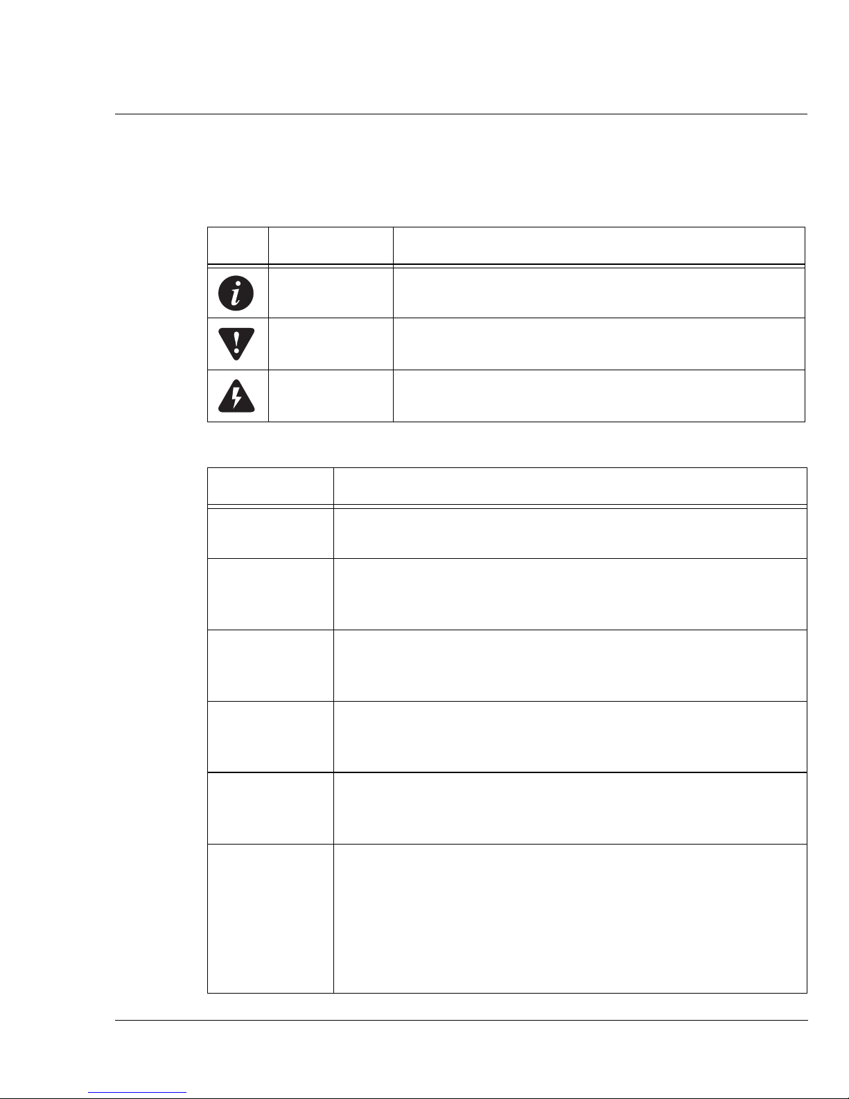
Table P.2 Notice Icons
Icon Notice Type Description
Table P.3 Text Conventions
Convention Description
Introduction
Note Information that describes important features or
instructions
Caution Information that alerts you to potential loss of data or
potential damage to an application, system, or device
Warning Information that alerts you to potential personal injury
Screen displays
This typeface represents information as it appears on the
screen.
Syntax
The word “syntax” means that you must evaluate the syntax
provided and then supply the appropriate values for the
placeholders that appear in angle brackets.
Commands The word “command” means that you must enter the
command exactly as shown and then press Return or Enter.
Commands appear in bold.
The words
“enter”
and “type”
Keyboard key
names
When you see the word “enter” in this guide, you must type
something, and then press Return or Enter. Do not press Return
or Enter when an instruction simply says “type.”
If you must press two or more keys simultaneously, the key
names are linked with a plus sign (+). Example:
Press Ctrl+Alt+Del
Word s in italics Italics are used to:
Emphasize a point.
Denote a new term at the place where it is defined in the text.
Identify menu names, menu commands, and software button
names. Examples:
From the Help menu, select Contents.
Click OK.
Avaya M770 M-ACCF/SF ATM Access Modules User’s Guide III
Page 6

Introduction
IV Avaya M770 M-ACCF/SF ATM Access Modules User’s Guide
Page 7

Contents
Chapter 1 Overview............................................................................................................. 1
Introduction ......................................................................................................... I
ATM Terminology ...................................................................................I
Finding Information in This Guide .......................................................... II
Conventions ........................................................................................... III
Contents................................................................................................................ i
List of Figures .................................................................................................. vii
List of Tables...................................................................................................... ix
ATM Access Modules ............................................................................... 1
Features and Benefits............................................................................... 1
ATM Benefits ...........................................................................................1
ATM Access Module Features ..............................................................2
Avaya M770 Frame Switch Domains....................................................... 2
M-ACC Module Architecture ............................................................... 2
Network Layer Concepts — LAN Emulation ........................................... 3
LAN Emulation Overview ....................................................................3
Emulated LAN Components ................................................................3
LAN Emulation Client (LEC) ....................................................3
LAN Emulation Server (LES) .................................................... 4
Broadcast and Unknown Server (BUS) ....................................4
LAN Emulation Configuration Server (LECS) .......................4
Emulated LAN Connections .................................................................5
Control VCCs ...............................................................................5
Data VCCs ....................................................................................6
Frame Ordering ...........................................................................7
Operation of the LAN Emulation .........................................................8
Connecting a LEC to an ELAN .................................................8
Registration ..................................................................................9
Address Resolution ...................................................................10
Connection Management ......................................................... 10
LAN Emulation Components in Your Network ..................10
Joining the ELAN ......................................................................12
Mapping Ethernet and ATM Addresses ................................12
What Happens to Unicast Frames? ........................................14
What Happens to Broadcast and Multicast Frames? ........... 14
Avaya M770 M-ACCF/SF ATM Access Modules User’s Guide i
Page 8

Contents
Network Layer Concepts — ATM & ATM Adaptation ........................... 15
The Layered Network Architecture ...................................................15
ATM Adaptation Layer (AAL) ...........................................................16
Asynchronous Transfer Mode (ATM) Layer ....................................16
ATM Basics .................................................................................16
ATM is Service Transparent .....................................................17
ATM is Connection-Oriented ..................................................18
ATM Interfaces ...........................................................................21
The ATM Layer and Cell Structure .........................................22
Physical Layer .......................................................................................24
Extending VLANs into the ATM Network .......................................24
Chapter 2 Applications ...................................................................................................... 27
Putting Your ATM Network Together .................................................... 27
Planning Your Network .......................................................................27
ATM Configuration Rules ...................................................................... 28
Extending VLANs Through the ATM Network ...................................... 29
ATM Connections Within Your Network .........................................30
Network Configuration Examples .......................................................... 31
ATM Backbone in the Building ...........................................................31
Avaya M770 Multitechnology Functionality ....................................33
Routing in the X-Switch Domain ........................................................34
Chapter 3 Installation......................................................................................................... 35
Installing the M-ACC Module ................................................................ 35
Safety Information ................................................................................35
Single-mode Module Laser Classification .........................................36
Multi-Mode Module LED Warning ...................................................36
Agency Approval ..................................................................................36
Device Support ......................................................................................36
Pre-installation Procedure ...................................................................36
Domain Usage Considerations................................................................ 37
Budget Calculation Examples .............................................................37
DRU Budget Information Window ....................................................38
Installing the Module ............................................................................. 39
Connecting a Cable to the ATM Port ......................................40
Removing an Existing ATM Access Module ....................................41
Post-Installation Checks .......................................................................42
Configuring the M-ACC Module............................................................ 43
M-ACC Module Default Settings .......................................................43
Connecting to the Serial Port ...................................................43
Establishing a Telnet Session ...............................................................44
ii Avaya M770 M-ACCF/SF ATM Access Modules User’s Guide
Page 9

Contents
Setting up the M-ACC Module .............................................................. 45
Changing the Default IP Address of the M-ACC Module
Using the CLI ........................................................................................45
To connect to the M-SPX/S Console port .............................. 45
Module Setup Main Menu ..................................................................46
ATM IP Configuration .........................................................................46
Assigning the M-ACC module IP address, Gateway and Net-
mask: ...........................................................................................46
Setting up the ATM Access Module ..................................................47
Chapter 4 X-Switch CLI & ATM Terminal Interface..................................................... 49
Introduction ........................................................................................... 49
M-ACC Module Architecture ............................................................. 49
Conventions Used .................................................................................. 50
X-Switch Command Line Interface (CLI) .............................................. 51
Commands Summary Table ...............................................................51
To connect to the M-SPX/S Console port .............................. 51
Module Setup Main Menu ..................................................................52
Reset the Module ..................................................................................52
Software Download to the X-Switch CPU ........................................53
Entering Software Download Parameters ............................. 53
Starting the Software Download Process ..............................54
Monitoring the Software Download Process ........................54
Set Primary Version ..............................................................................55
Set Defaults to Factory Settings .......................................................... 55
Create Report ........................................................................................ 55
Clear Mac Address Table .................................................................... 56
Configuration Copy .............................................................................56
ATM IP Configuration .........................................................................56
Assigning the M-ACC module IP address, Gateway and
Netmask: ..................................................................................... 57
ATM Access Module Terminal Interface for Configuring ATM
Parameters.............................................................................................. 58
Commands Tree Chart ......................................................................... 58
Logging On ............................................................................................58
Logging Off ...........................................................................................59
Managing the ATM Access Module ....................................................... 59
Submenus ..............................................................................................59
Main Menu Options .............................................................................61
Configuring System Parameters [1] ...................................................61
System Menu .............................................................................. 61
Display Submenu [1,1] .............................................................62
Initialize Submenu [1,2] ............................................................62
Passwords Submenu [1,3] ........................................................62
Reset Submenu[1,4] ...................................................................62
Avaya M770 M-ACCF/SF ATM Access Modules User’s Guide iii
Page 10

Contents
System Logger Submenu [1,5] .................................................63
Display FLASH Log Messages Submenu [1,5,1] ...................63
Display Memory Log Messages Submenu [1,5,2] .................64
System Software Download Submenu [1,6] ..........................65
Configuring an ATM Port [2] ..............................................................65
ATM access module Configuration ........................................65
Port Submenu [2,1] ....................................................................66
ATM Port Physical Submenu [2,1,6] .......................................67
VCC Submenu [2,2] ...................................................................67
Aging Submenu [2,2,4] .............................................................68
Administering IP and SNMP Management [3] ................................69
IP Submenu [3,1] ........................................................................69
SNMP Configuration Submenu [3,2] ......................................69
Extending VLANs into the ATM Network [4] .................................72
VN Configuration Menu ..........................................................72
Upgrading Software .............................................................................75
Preliminaries ..............................................................................75
Downloading ..............................................................................75
Monitoring the ATM Access Module ..................................................... 76
ATM Port Statistics ...............................................................................76
VCC Statistics ........................................................................................78
Chapter 5 Network Management and Monitoring........................................................ 79
Introduction ........................................................................................... 79
CajunView M770 Device Manager ........................................................ 80
Starting the M770 Manager ................................................................80
M770 Manager as Part of CajunView .....................................80
LANEMaster ........................................................................................... 81
Overview ................................................................................................81
Starting Cajun LANEMaster ...............................................................81
Cajun LANEMaster Views ..................................................................82
Overview .....................................................................................82
Appendix A Specifications .................................................................................................... 85
M-ACC ATM Access Module Technical Specifications........................... 85
Environmental, Safety, and EMC Specifications ..............................85
ATM Cable Specification .....................................................................85
Optical Standard Supported ....................................................86
SDH Standard Supported .........................................................86
Safety Information ................................................................................. 88
Important Safety Information .............................................................88
Appendix B Troubleshooting ............................................................................................... 89
Index ............................................................................................................................................... 91
iv Avaya M770 M-ACCF/SF ATM Access Modules User’s Guide
Page 11

Contents
How to Contact Us....................................................................................................................... 95
In the United States .............................................................................. 95
In the EMEA (Europe, Middle East and Africa) Region .................95
In the AP (Asia Pacific) Region ...........................................................97
In the CALA (Caribbean and Latin America) Region ..................... 97
Avaya M770 M-ACCF/SF ATM Access Modules User’s Guide v
Page 12

Contents
vi Avaya M770 M-ACCF/SF ATM Access Modules User’s Guide
Page 13

List of Figures
Figure 1.1 Basic LAN Emulation Client Connections ...............................5
Figure 1.2 VCCs in LAN Emulation Components.....................................7
Figure 1.3 The Flush Protocol. ......................................................................8
Figure 1.4 Connection Processes of the LEC to LANE Server..................9
Figure 1.5 Address Resolution.................................................................... 10
Figure 1.6 LAN Emulation Components...................................................11
Figure 1.7 LAN Emulation Clients and Ethernet Hosts..........................13
Figure 1.8 Network Layer Architecture.....................................................15
Figure 1.9 Service Processing......................................................................17
Figure 1.10 Communication Channels ........................................................18
Figure 1.11 Connection Terminology ..........................................................19
Figure 1.12 Switching Cells Using VPI and VCI Values ...........................20
Figure 1.13 ATM Interfaces ...........................................................................21
Figure 1.14 UNI Management Entities ........................................................22
Figure 1.15 ATM Cell Structure....................................................................23
Figure 1.16 VLAN to ELAN Mapping.........................................................25
Figure 1.17 Extending VLANs into the ATM Network. ...........................26
Figure 2.1 ATM Backbone in the Building................................................32
Figure 2.2 Avaya M770 Multitechnology Functionality .........................33
Figure 2.3 Routing in the X-Switch Domain. ............................................34
Figure 3.1 Inserting the Module into the Hub..........................................40
Figure 3.2 LED Indications for the M-ACC ATM Access Module ........42
Figure 4.1 Management Submenu Map ....................................................60
Figure 4.2 Main Menu..................................................................................61
Figure 4.3 System Menu............................................................................... 61
Figure 4.4 Display Submenu .......................................................................62
Figure 4.5 Passwords Submenu..................................................................62
Figure 4.6 Logger Submenu ........................................................................63
Figure 4.7 Display FLASH Log Messages Submenu............................... 63
Figure 4.8 Display Memory Log Messages Submenu.............................64
Figure 4.9 System Software Download Submenu.................................... 65
Figure 4.10 ATM Access Module Configuration Submenu......................65
Figure 4.11 Port Submenu ............................................................................. 66
Figure 4.12 Display Results ...........................................................................67
Figure 4.13 ATM Port Physical Submenu ...................................................67
Figure 4.14 VCC Submenu ............................................................................68
Figure 4.15 Aging Submenu..........................................................................68
Figure 4.16 Management Submenu .............................................................69
Avaya M770 M-ACCF/SF ATM Access Modules User’s Guide vii
Page 14

List of Figures
Figure 4.17 SNMP Submenu..........................................................................69
Figure 4.18 updSysAtt Submenu [3,2,6].......................................................71
Figure 4.19 Community Submenu [3,2,7]....................................................71
Figure 4.20 Virtual net Submenu ..................................................................72
Figure 4.21 ATM Submenu............................................................................76
Figure 4.22 ATM Port Statistics Screen ........................................................77
Figure 4.23 VCC Statistics Display Example...............................................78
Figure 5.1 Cajun LANEMaster Window....................................................83
viii Avaya M770 M-ACCF/SF ATM Access Modules User’s Guide
Page 15

List of Tables
Table P.1 Finding Information.................................................................... II
Table P.2 Notice Icons.................................................................................III
Table P.3 Text Conventions .......................................................................III
Table 1.1 Control VCCs................................................................................5
Table 1.2 Data VCCs.....................................................................................6
Table 3.1 Avaya M770 Module DRU Budget.......................................... 37
Table 3.2 M-ACC LEDs Descriptions....................................................... 42
Table 3.3 M-ACC Module Default Settings.............................................43
Table 4.1 Users and their Privileges .........................................................58
Table 4.2 Operational Meanings of Display FLASH Log
Submenu Items........................................................................... 63
Table 4.3 Operational Meanings of Display Memory Submenu Items64
Table 4.4 Operational Meanings of Port Submenu Items .....................66
Table 4.5 VCC Submenu Items and their Operational Meanings........ 68
Table 4.6 Configure Submenu Items and their Operational
Meanings .....................................................................................70
Table 4.7 Configure Submenu Items and their Operational
Meanings .....................................................................................73
Table 4.8 Port Statistics Display Items and their Meanings.................. 77
Table 4.9 Statistics Display Items and their Meanings ..........................78
Table A.1 Environmental Specifications...................................................85
Table A.2 Safety and EMC Standards Compliance.................................85
Table A.3 Standard Multi-mode Cable Specifications ............................ 86
Table A.4 Standard Multi-mode Cable Specifications (continued) ...... 87
Table A.5 Standard Single-Mode Cable Specifications
(OC-12c/OC-3c Short Reach) ...................................................87
Table B.1 Troubleshooting Tips.................................................................89
Avaya M770 M-ACCF/SF ATM Access Modules User’s Guide ix
Page 16

List of Tables
x Avaya M770 M-ACCF/SF ATM Access Modules User’s Guide
Page 17

Chapter 1
Overview
ATM Access Modules
There are two M-ACC OC-12 ATM Access modules for the Avaya M770
Multifunction switch:
• M-ACCF: 500m, Multimode fiber, can also be OC-3 reduced range
• M-ACCSF: 15 km, Single-mode fiber, can also be OC-3
The M-ACC ATM Access modules need the following S/W Versions:
• M-ACCF/SF ATM Entity S/W Version 1.8
• M-ACCF/SF X-Switch Module S/W Ver. 4.0.7
• M-SPX/M-SPS Embedded S/W 3.2.1 and higher.
Features and Benefits
ATM Benefits
This Section describes the main features of the M-ACC OC-12 module and the
benefits of ATM within your network. The following topics are described:
•ATM Benefits
• ATM Access Module Features
The ATM module provides a high-speed ATM connection between your
Avaya M770 X-Switch domain and the ATM network.
Positioned within a workgroup or departmental LAN, the ATM access module
provides a fast ATM uplink to the building or ATM campus.
Redundant links protect your Switch from network and equipment failure, while
the software upgrade feature future-proofs your Switch by allowing you to add new
features as they become available.
ATM is the only technology specifically designed to carry voice, video and data
traffic simultaneously and to provide the required level of service that these
different applications need in order to run effectively across a network. ATM
provides the following benefits:
• It is easy and of low cost to add additional services to the ATM network.
• Services can be added as and when they are needed. It is easier to scale ATM
networks compared to other network technologies.
• ATM devices interoperate with your existing network. LAN Emulation (LANE)
is a standards-based technology specifically designed to provide
interoperability between existing Ethernet/Fast Ethernet networks and ATM
Avaya M770 M-ACCF/SF ATM Access Modules User’s Guide 1
Page 18

Chapter 1 Overview
networks. LANE allows users to interoperate with ATM or traditional LAN
based servers over ATM for higher performance and functionality.
ATM Access Module Features
The following list summarizes the ATM access module features. These features are
described in more detail in this guide.
• Conforms to ATM Forum Standards
• OC-12c 622Mbps Interface
— SONET (STS 3c/STS 12c) compliant (SDH STM-1/STM-4)
— Multimode fiber, SC/SM connectors
—Single-mode fiber.
• LAN Emulation (LANE) version 1.0
— 16 Emulated LAN Clients
— 3,740 Virtual Circuits
— 8,000 remote MAC Addresses
• User-To-Network Interface (UNI) version 3.0 and 3.1
• Interim Local Management Interface (ILMI)
• AAL5 ATM Adaptation Layer
• 16 ELAN/VLAN associations (in the range from VLAN 1 to 254)
• Data buffer to store 16,000 ATM cells
• High performance with fast data transfer
— Wire Rate Transmission on ATM port
• Redundant Links from two different modules protect your network against
cable and equipment failure
• For Management you can use:
— Avaya’s CajunView™ SNMP Manager
— TELNET
Avaya M770 Frame Switch Domains
The Avaya M770 supports two Frame Switches, named DomainXs: DomainXL (Left
DomainX) spans slots 1-7, and DomainXR (Right DomainX) spans slots 8-14. Each
DomainX supports up to 6 Gbytes of bandwidth. You can insert the M32-100T into
either DomainX, provided you don't exceed the maximum of 100 Domain Resource
Units (DRUs) per DomainX. Each module uses a certain number of DRUs; the
M32-100T uses 12 DRUs.
M-ACC Module Architecture
The M-ACC module consists of separate X-Switch and ATM entities. The X-switch
CPU connects the M-ACC module to the Avaya M770 X-Domain. The ATM CPU
performs all ATM signalling. Each entity has it’s own embedded software.
2 Avaya M770 M-ACCF/SF ATM Access Modules User’s Guide
Page 19

Network Layer Concepts — LAN Emulation
The following Sections describe the LAN emulation and ATM adaptation concepts
behind the network layer architecture of a typical ATM network.
Chapter 2 describes how to plan your ATM network and provides some examples
of where to use the ATM access module within an ATM network.
LAN Emulation Overview
LAN Emulation (LANE) is a method of connecting LAN users over an ATM network
which enables them to communicate with each other as if they were operating over
traditional LANs. LANE can be configured in an ATM network in several ways:
• To connect legacy end stations directly to other legacy systems, as well as to
servers, routers, switches and other networking devices attached to the ATM
network.
• To connect bridged-LAN environments to each other over ATM. In this case the
Emulated LAN acts as a bridge on the ATM network.
• To connect ATM end stations to each other, enabling communication between
them.
Chapter 1 Overview
More than one emulated LAN can operate on the same ATM network. However,
each of the emulated LANs is independent of the others and users cannot
communicate directly across emulated LAN boundaries.
Emulated LAN Components
LAN Emulation is implemented as a set of connection services collectively called an
emulated LAN (ELAN). Each ELAN is composed of a set of LAN Emulation Clients
(LEC) and a single LAN Emulation Service. The latter consists of a LAN Emulation
Configuration Server (LECS), a LAN Emulation Server (LES), and a Broadcast and
Unknown Server (BUS).
LAN Emulation Client (LEC)
Each LEC is incorporated in an ATM edge device, such as the M-ACC module and
represents a set of the device’s LAN users to the ATM network. A LEC has a unique
LEC ID as well as an ATM address by which it is known in the emulated LAN. It
handles the forwarding of its LAN users’ data frames over the ATM network to
their destination, a task which also includes ascertaining the destination LEC
address and setting up the connection between them.
Also provided is a MAC-level emulated Ethernet service interface to higher level
software which implements the LAN Emulation User to Network Interface (LUNI).
An ELAN is assigned a name (ELAN name). A LEC joining an ELAN may use the
ELAN name in the configuration or join phase.
Avaya M770 M-ACCF/SF ATM Access Modules User’s Guide 3
Page 20

Chapter 1 Overview
LAN Emulation Server (LES)
The LES coordinates and controls an Emulated LAN. It provides the central
“directory” service of an emulated LAN to which a LEC can turn to look up the
ATM address of another LEC. The LES directory contains a table of LAN
destinations (LAN destination refers to either a MAC address or a Route Descriptor)
together with the ATM addresses of the LECs that represent them. In order to
transmit a data frame to a particular LAN destination, the LEC sends the data frame
to the LEC that represents that LAN destination. If the LEC does not already know
the destination LEC’s address, it can send the LAN destination to the LES to look it
up (resolve). To populate the LES directory, the LECs may register the LAN
destination of LAN stations they represent with the LES. Every Route Descriptor
must be registered with the LES.
The LANE Service normally resides on a central ATM switch, such as the M770
ATM Switch, but may reside on an ATM end station instead.
Broadcast and Unknown Server (BUS)
The BUS is the LANE connection service which handles ATM traffic other than
direct transmissions between LECs. It handles the following:
• Data sent by a LEC to the broadcast MAC address
• All multicast traffic
• Initial unicast frames which are sent by a LEC before the data direct virtual
connection to the ATM address has been resolved
• Unknown traffic
• All broadcast, multicast and unknown traffic to and from a LEC passes through
a single BUS.
The BUS also handles ATM connections and manages its distribution group.
LAN Emulation Configuration Server (LECS)
The LECS assigns individual LAN Emulation Clients to different emulated LANs.
Based on its own programming, configuration database and information provided
by clients, it assigns any client which requests configuration information to a
particular emulated LAN service by giving the client the LES’s ATM address. This
method supports the ability to assign a client to an emulated LAN based on either
the physical location (ATM address) or the identity of a LAN destination which it is
representing (ELAN name). LECs obtain information from a LECS using the
configuration protocol.
4 Avaya M770 M-ACCF/SF ATM Access Modules User’s Guide
Page 21
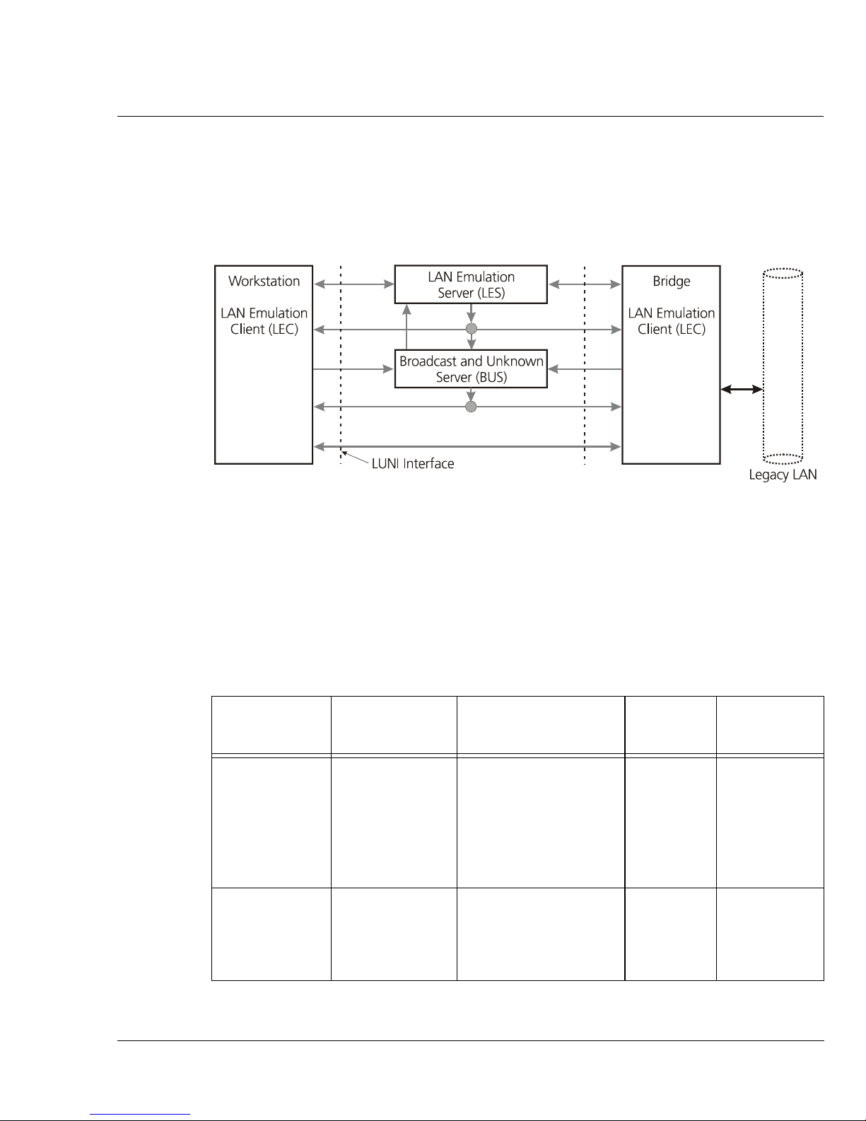
Emulated LAN Connections
LECs and LESs communicate with each other by means of ATM virtual channel
connections (VCCs). Control signals and data transmissions are handled by separate
VCCs: Control VCCs and Data VCCs.
Figure 1.1 Basic LAN Emulation Client Connections
Chapter 1 Overview
Control VCCs
The control VCCs carry control traffic such as LE_ARP requests and responses. On
initialization, control VCCs are established between LEC and LES (bi-directional
control-direct VCC and control-distribute VCC) as well as a bi-directional configuration
VCC between LEC and LECS. Characteristics of the control VCCs are summarized
in Table 1.1.
Table 1.1 Control VCCs
VCC Name From/To Information carried
Configuration LEC<==>LECS LEC requests and
receives
Initialized
by
Duration
LEC While
needed
configuration
information from
LECS, including LES
address
Control-direct LEC<==>LES LEC sends and
receives controls
from LES, including
LEC Membership
of LEC in
ELAN
LE_ARP information
Avaya M770 M-ACCF/SF ATM Access Modules User’s Guide 5
Page 22

Chapter 1 Overview
Table 1.1 Control VCCs (Continued)
VCC Name From/To Information carried
Controldistribute
LES==>LEC LES distributes
control traffic to
LECs, including
Initialized
by
Duration
LES Membership
of LEC in
ELAN
LE_ARP information
Data VCCs
Data VCCs carry data frames between LECs and between a LEC and the BUS.
Unicast data is normally sent from one LEC to another LEC by data-direct VCCs.
Data direct VCCs are set up dynamically in a SVC environment by a transmitting
LEC after ascertaining the ATM LEC destination address for the packet to be
transmitted. Once established, a data-direct VCC remains in place for transmission
of subsequent traffic between the two LECs. However, a data direct VCC that
remains unused for VCC-Timeout-period is released by the LEC.
A multicast data VCC pair (multicast-send and multicast-forward) are established
between a LEC and the BUS in order to allow the LEC to send and receive multicast
data. In addition, initial unicast data (data whose LEC destination has not yet been
ascertained by the transmitting LEC) is sent on the multicast-send VCC to the BUS
which forwards it to all other LECs in the same ELAN. Characteristics of the data
VCCs are summarized in the following table:
Table 1.2 Data VCCs
VCC
Name
Datadirect
From/To
LEC<==>LEC Point-to-point
Information
carried
Unicast data
between LECs
Initialize
d by
Duration
LEC Established by
need and released
when unused for
VCC-Timeout-
Multicastsend
LEC<==>BUS LEC sends
multicast and
period
LEC Membership of
LEC in ELAN.
.
initial unicast
data to BUS
Multicastforward
BUS==>LEC BUS distributes
data traffic to
BUS Membership of
LEC in ELAN.
LECs
6 Avaya M770 M-ACCF/SF ATM Access Modules User’s Guide
Page 23
Chapter 1 Overview
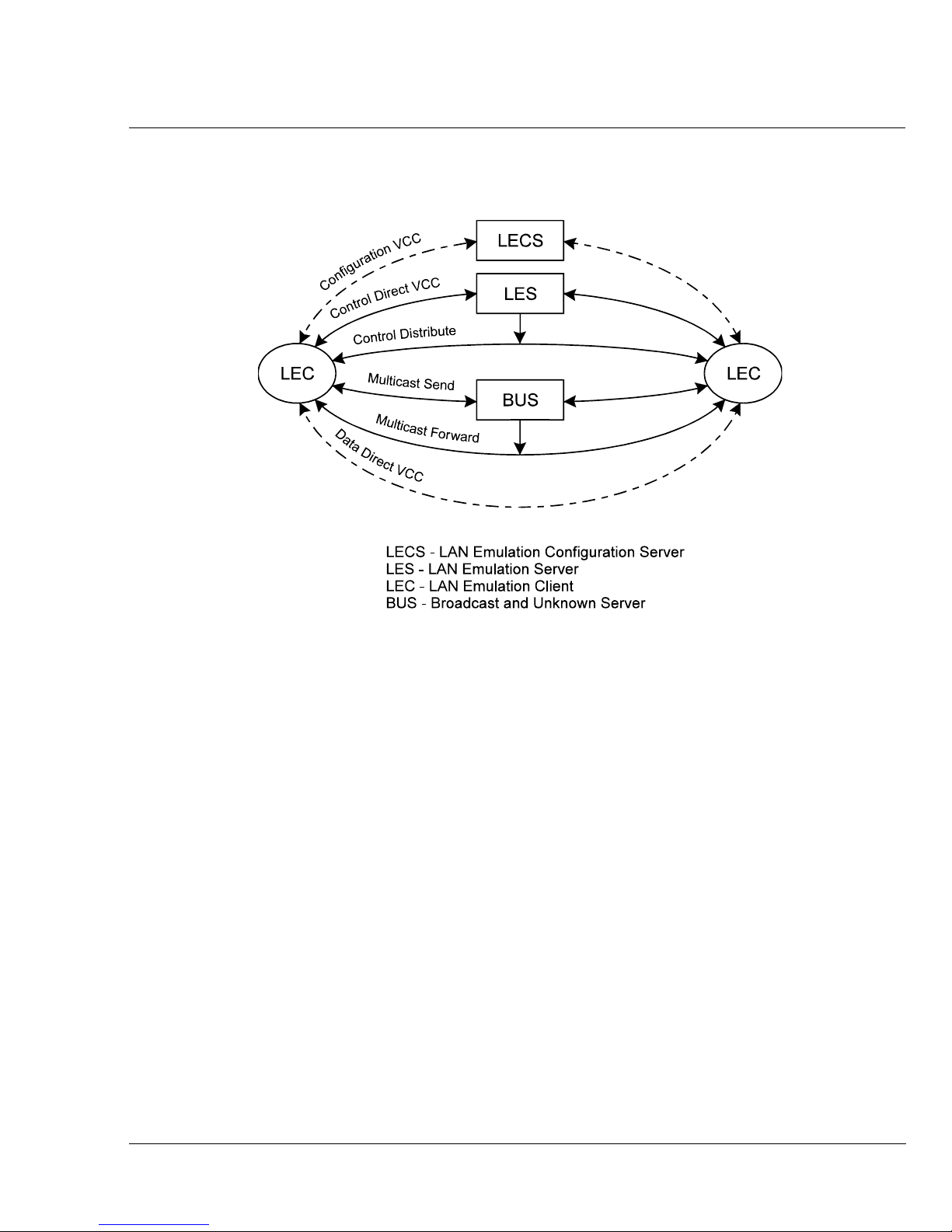
Figure 1.2 illustrates the VCCs active among LAN Emulation Components.
Figure 1.2 VCCs in LAN Emulation Components
Frame Ordering
There are two paths for unicast frames between a sending LAN Emulation Client
and a receiving client: one via the BUS and one via a data direct VCC between them.
For a given LAN destination, a sending client is expected to use only one path at a
time, but the choice of paths may change over time. Switching between those paths
introduces the possibility that frames may be delivered to the receiving client out of
order. Delivery of out-of-order frames between two LAN endpoints is
uncharacteristic of LANs, and undesirable in an ATM emulated LAN. The flush
protocol ensures the correct order of delivery of unicast data frames.
Flush Protocol
When switching between paths, the sender first transmits a flush message down the
old path and suspends further transmission to that LAN destination. When the
flush message is returned by the receiving client (via control VCCs), the sender
knows that all previous messages for that LAN destination have been processed
and it can start using the new path.
Avaya M770 M-ACCF/SF ATM Access Modules User’s Guide 7
Page 24
Chapter 1 Overview
Figure 1.3 shows the various stages of the flush protocol:
Figure 1.3 The Flush Protocol.
Switch Data Path from
Multicast Send to
Data Direct using
Flush Protocol
5
.
F
l
u
s
h
_
R
e
s
6. Flush_Res
1
.
D
a
t
a
2. Data
q
e
R
_
h
s
u
l
F
.
4
7. Data
Operation of the LAN Emulation
The following functions are performed by the LAN Emulation. The LAN Emulation
Clients (LEC) and the LAN Emulation Servers interact by way of a well-defined
interface (LUNI).
• Connecting a LEC to an ELAN
• Address Registration
• Address Resolution
• Data Transfer
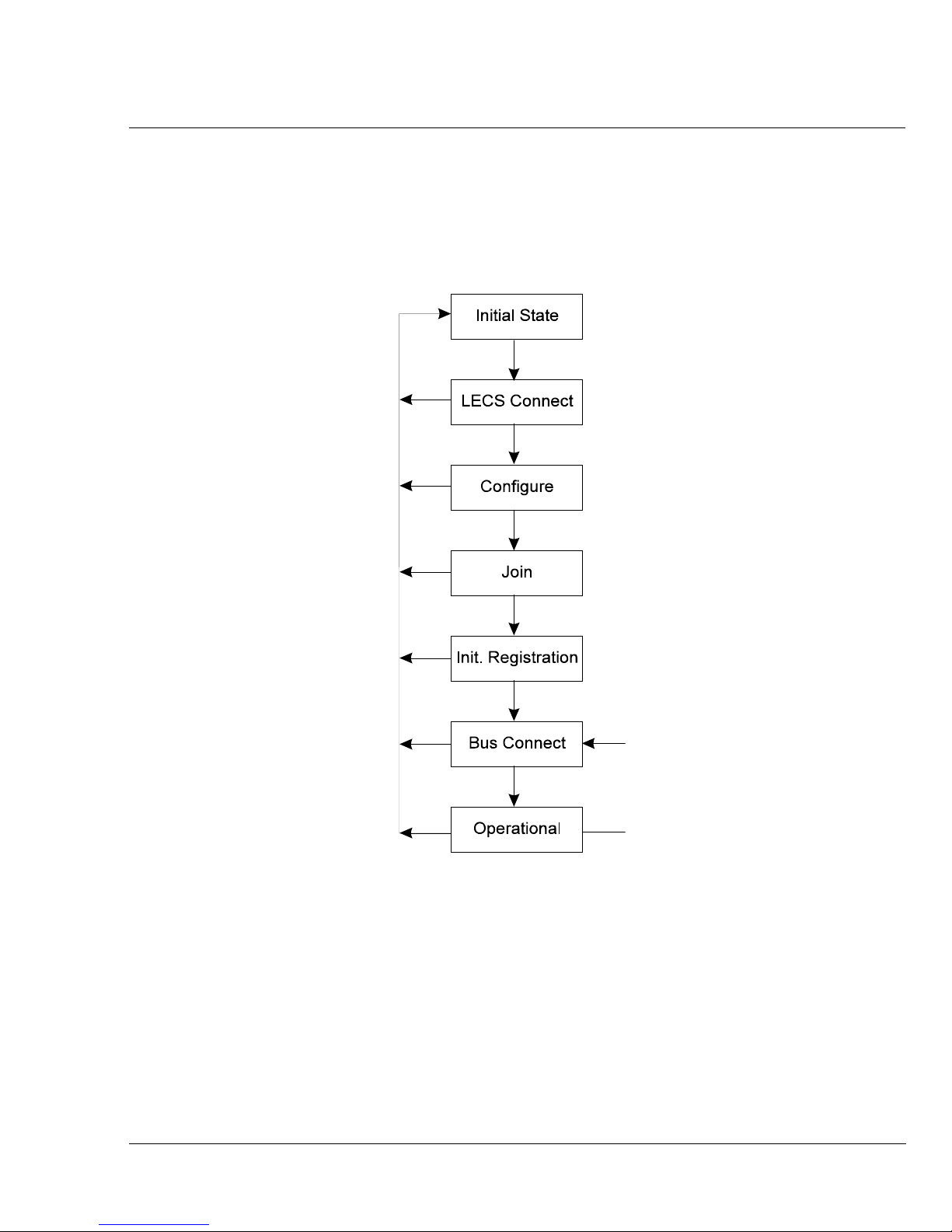
Connecting a LEC to an ELAN
The connection function of the LEC with the LAN Emulation Server (LES) includes
the following:
• LECS connect phase in which a LEC establishes a configuration data-direct VCC
to the LECS (optional).
• The configuration phase in which the LEC discovers the LES.
• The join phase in which the LEC establishes its control connections to the LES.
The LEC may also implicitly register one MAC address with the LES.
• The registering by the LAN Emulation Client of any number of MAC addresses
and/or route descriptors.
• The establishment of a connection to the BUS by the LAN Emulation Client.
8 Avaya M770 M-ACCF/SF ATM Access Modules User’s Guide
Page 25
Chapter 1 Overview
The LECS Connect and Configuration phases may be bypassed for certain
applications. The Registration phase may also be bypassed if the LEC performs
required address registration during the Join phase.
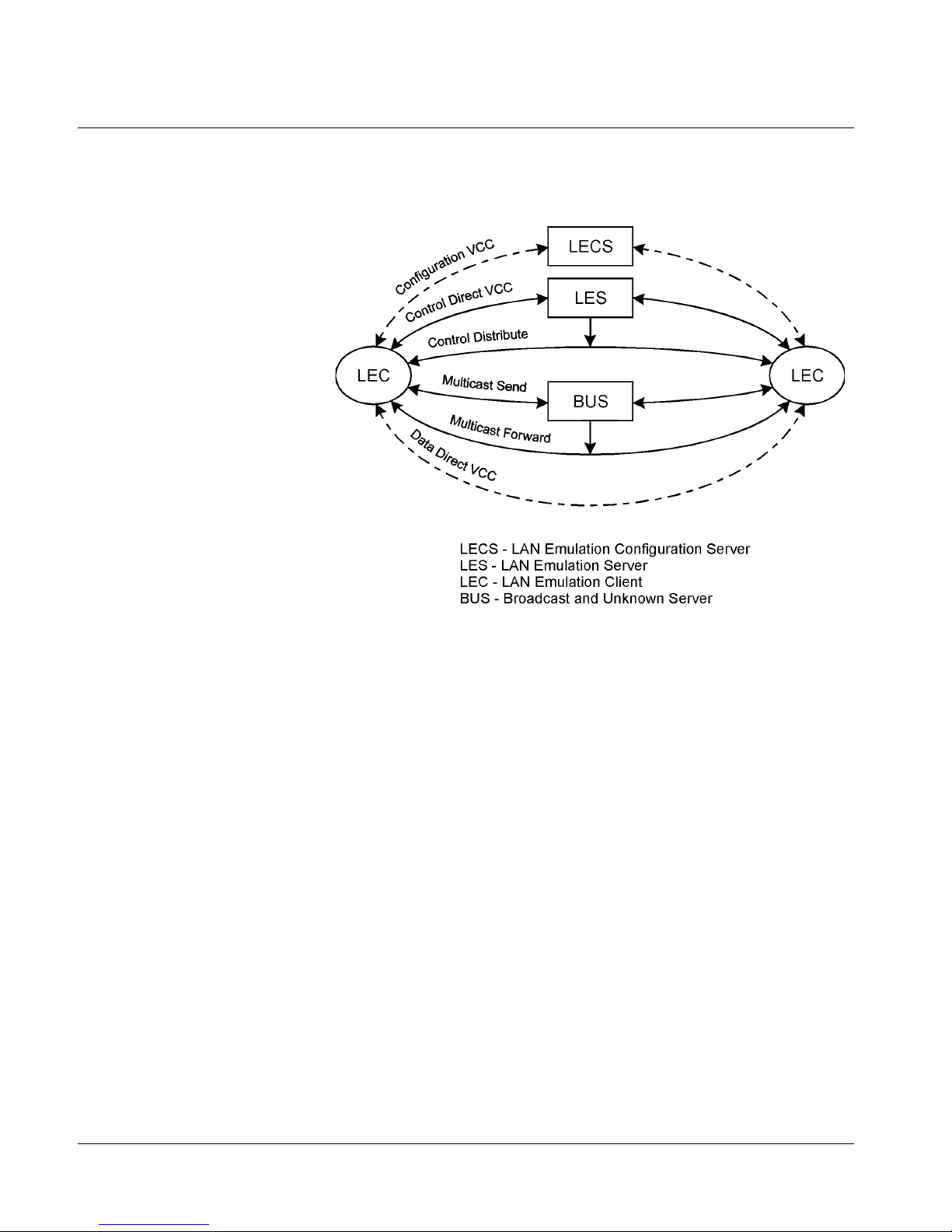
The Processes connecting the LEC to the ELAN are shown in Figure 1.4.
Figure 1.4 Connection Processes of the LEC to LANE Server
Registration
The address registration function is the mechanism by which LECs provide address
information to the LAN Emulation Server. The LAN destinations may also be
unregistered as the state of the client changes. A client must either register all LAN
destinations for which it is responsible or join as a proxy to other MAC addresses.
Avaya M770 M-ACCF/SF ATM Access Modules User’s Guide 9
Page 26
Chapter 1 Overview
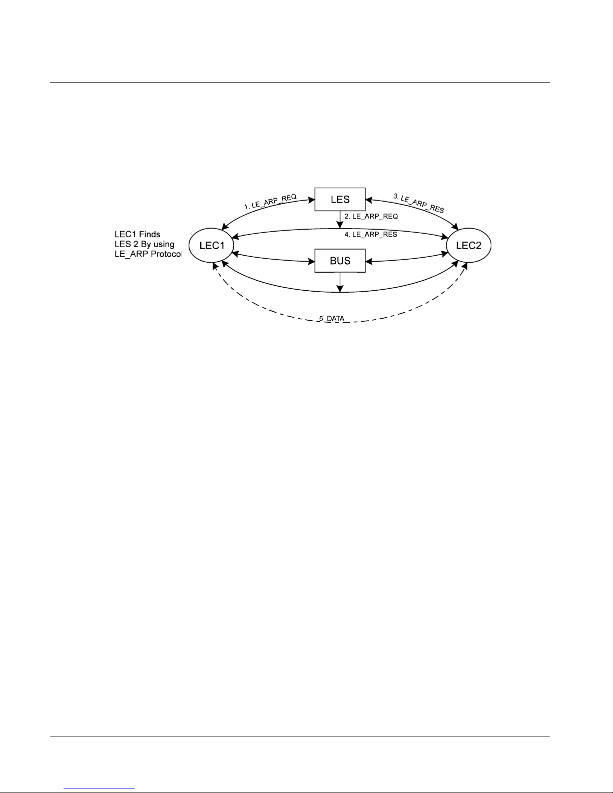
Address Resolution
Address resolution is the procedure by which a LEC associates a LAN destination
with the ATM address of another LEC or the BUS. Address resolution allows clients
to set up data direct VCCs to carry frames (refer to Figure 1.5).
Figure 1.5 Address Resolution
Connection Management
In Switched Virtual Connection (SVC) environments, the LAN Emulation entities
(LEC, LES and BUS) set up connections between each other using UNI signaling.
LAN Emulation Components in Your Network
Each Emulated LAN consists of a single LANE Service, and a number of LAN
Emulation clients.
A LANE Service consists of:
•A LAN Emulation Server (LES)
•A Broadcast and Unknown Server (BUS)
•Optional LAN Emulation Configuration Server (LECS).
Figure 1.6 shows a logical view of a typical ELAN.
10 Avaya M770 M-ACCF/SF ATM Access Modules User’s Guide
Page 27
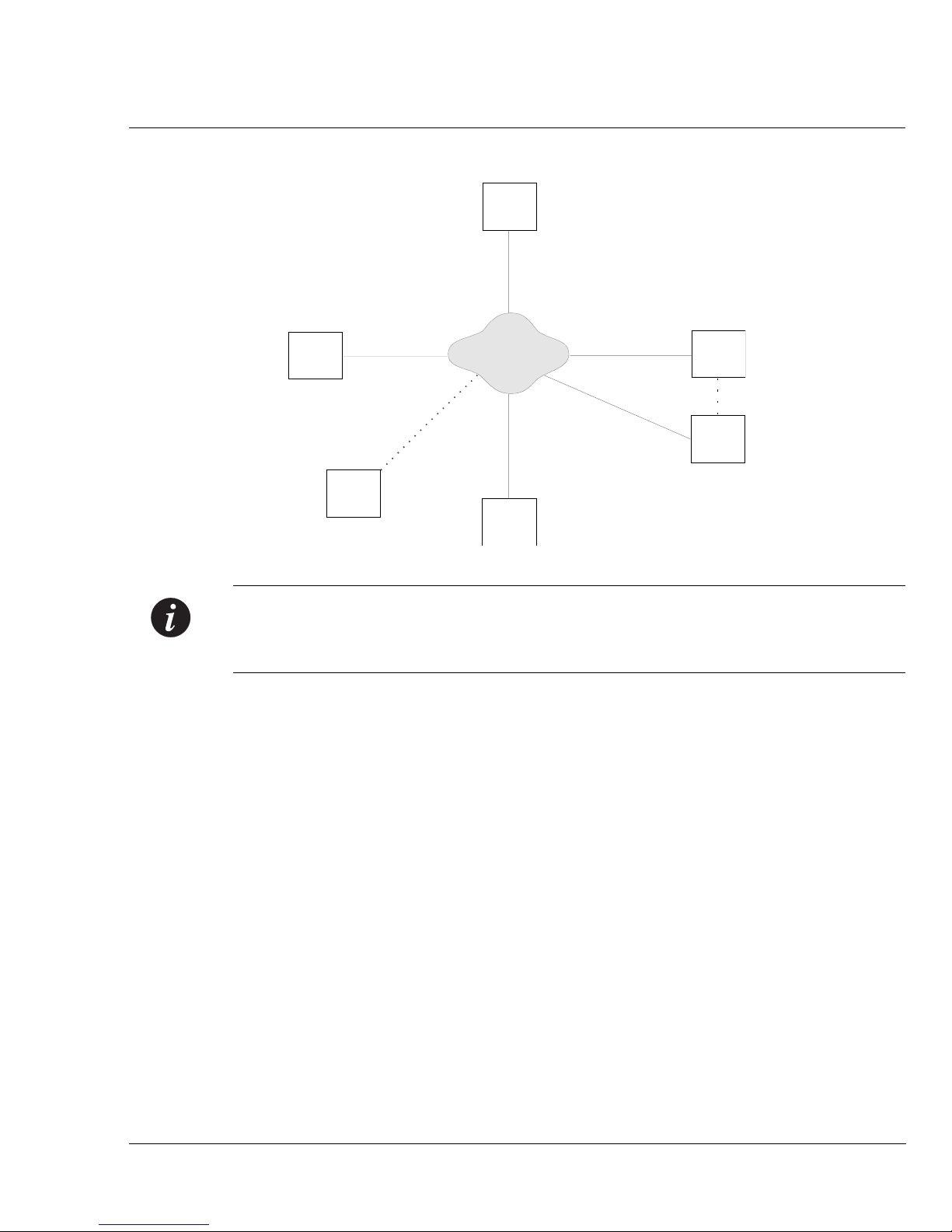
Figure 1.6 LAN Emulation Components
Server
(LES)
Chapter 1 Overview
BUS
Router
AT M N e t w o r k
LECS
(optional)
Client
(LEC)
Client
(LEC)
Note: The router shown in Figure 1.6 is not a LAN Emulation component, but
would be required should a device on one Emulated LAN need to communicate
with a device on another Emulated LAN.
LAN Emulation and Avaya Devices
LAN Emulation components are implemented in ATM devices. The LAN
Emulation standards do not specify how each vendor implements each of these
components.
Avaya provides a wide range of ATM equipment, and the following example is just
one way in which you can implement an Emulated LAN using Avaya devices.
An Example:
• The Avaya M770 ATM switch incorporates the BUS, LES and LECS
components. These components are known collectively as LANE Services.
• The M-ACC module has 16 LAN Emulation Clients (LECs); one for each of the
Virtual LANs (VLANs) supported by the module.
Avaya M770 M-ACCF/SF ATM Access Modules User’s Guide 11
Page 28

Chapter 1 Overview
Joining the ELAN
Before a LAN Emulation Client (LEC) can transmit any Ethernet frames onto the
ATM network it must first join an ELAN. To join the ELAN:
1 The LEC must know the name of the ELAN it is to join.
The ELAN name is specified through the management software on the Switch.
2 The LEC must communicate with the LAN Emulation Server (LES) that is
serving that ELAN.
To communicate with the LES, the LEC must first locate the LES. The LEC can
find the ATM address of the LES in one of the following ways:
— If there is a LAN Emulation Configuration Server (LECS) on the network,
— The way in which the LECS determines which LES the LEC needs to
— If the network does not have a LECS, the LEC gets the LES address from the
3 The LEC must have a connection to the Broadcast and Unknown Server
(BUS).
When the LEC has joined the LES, the LES helps the LEC locate the Broadcast
and Unknown Server (BUS) associated with that ELAN.
the LEC gets the address of the LES from the LECS.
communicate with, depends on the policy that the LECS is running. Refer to
the user guide that accompanies your LECS for more details of the policies
your LECS uses.
management software on the ATM device.
Locating the LECS
Before the LEC can ask the LECS for the address of the LES, the LEC must first
locate the LECS as follows:
• The LEC can use a well known ATM address that is reserved for the LECS. The
well known address is pre-programmed into most LECS devices. The well
known address is: 47.00.79.00.00.00.00.00.00.00.00.00.00.00.A0.3E.00.00.01.00
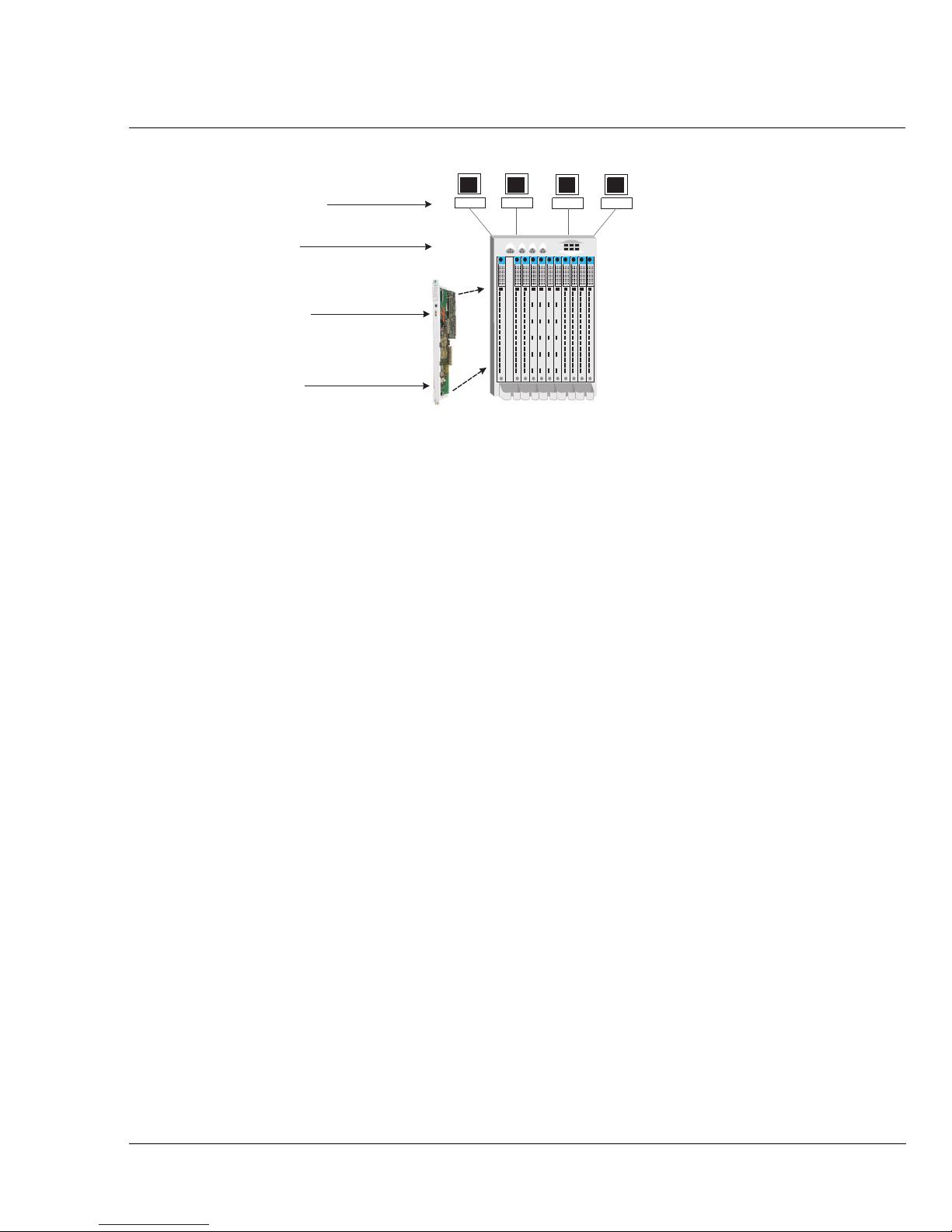
Mapping Ethernet and ATM Addresses
Each device connected to an Ethernet port has one or more MAC addresses.
Each ATM device has a number of LAN Emulation clients, and each LAN Emulation
Client (LEC) has an ATM address. An example of this is shown in Figure 1.7.
12 Avaya M770 M-ACCF/SF ATM Access Modules User’s Guide
Page 29
Chapter 1 Overview
Figure 1.7 LAN Emulation Clients and Ethernet Hosts
Hosts with
MAC Addresses
Avaya M770
Multifunction Switch
ATM Port with
16 LAN Emulation Clients (LECs)
each with an ATM Address
ATM Access
Module
These clients represent (act as a proxy for) devices connected to the Ethernet ports.
Whenever an Ethernet device wants to communicate with another device over the
ATM network, the LEC must first discover the ATM address of the LEC that is
acting as a proxy for the destination MAC address. The LEC must do this for each
unicast Ethernet frame sent. The process is known as Address Resolution.
Address Resolution
The process by which a LEC associates a LAN destination address with the ATM
address of another LEC (or the BUS) is known as Address Resolution.
Each LEC keeps a LAN Emulation ARP Table (which should not to be confused with
the IP ARP Table). The ARP Table lists the remote destination MAC addresses and
the ATM address of the LEC through which each destination MAC address can be
reached.
Prior to sending a frame with a known destination, the LEC checks the ARP Table to
see if the destination MAC address of the frame is listed in the ARP Table. The
action the LEC then takes depends on whether the MAC address is listed in the ARP
Table:
• If the destination MAC address is listed in the ARP Table:
— and there is an ATM connection to that LEC, the frame is sent directly to
that LEC.
— and an ATM connection has not already been set up, the LEC sets up an
ATM connection.
• If the destination MAC address is not listed in the ARP Table:
the LEC sends the frame to the BUS. The BUS then sends the frame to all LECs
on the Emulated LAN.
Sending a frame to every LEC is an inefficient use of resources, so the LEC also tries
to locate the MAC address for future use.
To discover the correct address, the LEC uses a process called LAN Emulation
Address Resolution Protocol (LE_ARP).
Avaya M770 M-ACCF/SF ATM Access Modules User’s Guide 13
Page 30

Chapter 1 Overview
LAN Emulation Address Resolution Protocol (LE_ARP)
An LE_ARP request is sent to the LES to locate the destination MAC address. The
LES in turn sends the LE_ARP request to all of the LECs in the Emulated LAN.
LECs represent (act as a proxy for) MAC address devices connected to the Ethernet
ports. When a LEC receives an LE_ARP request it checks whether the MAC address
is on its Switch. It does this by checking the entries in the Switch database.
If the MAC address belongs to one of the devices connected to an Ethernet port, the
LEC sends an LE_ARP response to the LEC that sent the original LE_ARP request.
The LEC that sent the LE_ARP request adds this information to its ARP Table. The
LEC then sets up a direct connection through the ATM network to the appropriate
LEC, so that subsequent frames are forwarded more efficiently.
What Happens to Unicast Frames?
The path a unicast frame takes through the ATM network depends on whether the
location of the destination address is known to the sending LEC.
• If the location of the destination address is known, the LEC sets up a direct
connection to the LEC serving the destination address.
• If the location of the destination address is unknown, a unicast frame is sent
to the Broadcast and Unknown Server (BUS); where it is treated in the same way as
a broadcast or multicast frame.
In addition the sending LEC attempts to locate the LEC serving the destination
address. It does this using the LE_ARP process, described in “LAN Emulation
Address Resolution Protocol (LE_ARP)”.
What Happens to Broadcast and Multicast Frames?
Each Emulated LAN (ELAN) acts as a broadcast domain. When a broadcast or
multicast frame is passed to the LEC for transmission, the frame is sent to the
Broadcast and Unknown Server (BUS).
When the LEC receives a broadcast, multicast, or unicast frame it checks to see if it
originally sent the frame, and then does the following:
• If the LEC sent the frame, it discards the frame.
• If the LEC did not send the frame, the LEC passes the frame to the Ethernet
device so that it can be forwarded to the appropriate port(s)
Note: Unlike broadcast and multicast frames, the number of unicast frames that can
be sent to the BUS every second is limited so as not to overload the BUS and LECs
with too much traffic.
14 Avaya M770 M-ACCF/SF ATM Access Modules User’s Guide
Page 31

Network Layer Concepts — ATM & ATM Adaptation
This Section describes the following concepts behind the network layer architecture
of a typical ATM network:
• The Layered Network Architecture
• ATM Adaptation Layer (AAL)
• Asynchronous Transfer Mode (ATM) Layer
•Physical Layer
The Layered Network Architecture
Asynchronous Transfer Mode (ATM) is one part of the layered network architecture.
This architecture is shown in Figure 1.8.
Each of the layers is discussed in turn; starting with the Upper Layer and working
down to the Physical Layer.
Figure 1.8 Network Layer Architecture
ULP PDUs
Chapter 1 Overview
Key
PDUs
LAN Emulation
Frames
AAL5 PDUs
ATM Ce l l s
SONET or SDH
fr ames
med i a
Logical fl ow
Physical flow
Protocol Data Units
Avaya M770 M-ACCF/SF ATM Access Modules User’s Guide 15
Page 32

Chapter 1 Overview
ATM Adaptation Layer (AAL)
Ethernet frames can be between 64 and 1514 bytes in length. ATM transmits data in
fixed length cells. Each cell contains 48 bytes of user data. The ATM Adaptation Layer
(AAL) converts data between the Ethernet and ATM formats.
The AAL has a Segmentation and Reassembly (SAR) sub-layer that does the
conversion.
In the sending device the LEC passes the Ethernet frames to the SAR. The SAR
converts the user data into fixed length cells, and passes these cells to the ATM
Layer for transmission across the ATM network.
In the receiving device, the SAR converts the ATM cells back into the appropriate
user data again, and passes this data to the LEC.
As ATM can carry different traffic types (for example, voice, video, and other data),
several Adaptation Layer protocols have been defined. These protocols operate
simultaneously within the Adaptation Layer, and allow the ATM Layer to support
different applications and traffic types.
Note: The M-ACC module uses the AAL5 ATM Adaptation Layer protocol, which
is a data-oriented protocol. The ATM access module will only work with other
devices using the AAL5 ATM adaptation layer protocol.
Asynchronous Transfer Mode (ATM) Layer
Asynchronous Transfer Mode (ATM) is a connection-oriented transmission protocol
that has the following features:
• ATM uses the Signalling Protocol (Q.2931) to dynamically create, maintain and
clear ATM connections between end-systems.
• ATM uses fixed length packets known as cells, and each cell identifies the
connection to be used.
• ATM is transparent to the multiple services it supports and can carry cells from
different applications over the same physical connection.
• ATM has well-defined user and network interfaces.
ATM Basics
Asynchronous Transfer Mode (ATM) technology transfers network traffic,
including voice, video, and data, at high speed. Using this connection-oriented
networking technology, centered by a switch, you can set up a great number of
virtual connections to support multiple applications through the same physical
connection. The switching technology enables dedicated bandwidth for each
application, overcoming the problems that exist in a shared-media networking
technology, like Ethernet, Token Ring, and FDDI. ATM allows different types of
16 Avaya M770 M-ACCF/SF ATM Access Modules User’s Guide
Page 33

Chapter 1 Overview
physical layer technology to share the same higher layer — the ATM layer.
ATM uses fixed length packets called cells. The ATM cell is defined as 48 bytes of
payload and 5 bytes of header information totaling 53 bytes. The header contains
enough information to allow the network to forward each cell to its proper
destination. The cell header also provides the network with the ability to implement
congestion control and traffic management mechanisms.
ATM advantages include the fact that:
• Fixed-length cells offer smaller and more predictable switching delays, because
cell switching is less complex than variable-length packet switching.
• Having all the data in the same cell format also dramatically increases the speed
of transmission, by eliminating the need for protocol recognition and decoding.
A good analogy is containerized shipping, where uniform shape and weight
containers with standardized labelling, ease and speed up processing.
• Cell switching is less complex and more reliable. ATM hardware can be
implemented more efficiently because control structures, buffers, and buffer
management schemes can be designed to known size criteria.
• Cell-relay switches can process cells in parallel, achieving speeds that far exceed
the limitations of packet switch architectures.
• The cell format also allows for multi-protocol transmissions. Since ATM is
protocol transparent, the various protocols can be transferred at the same time.
With ATM, one line can carry phone, fax, video, data and other information
simultaneously. This multiprotocol advantage also offers scalability, greatly
reducing the configuration changes necessary for adding a new traffic type to
your network.
ATM is Service Transparent
ATM allows for the high speed transfer of a wide range of user traffic, including
voice, video and other data.
The cell format means that more than one service (traffic type) can be multiplexed
over the same physical line, see Figure 1.9.
Figure 1.9 Service Processing
Avaya M770 M-ACCF/SF ATM Access Modules User’s Guide 17
Page 34

Chapter 1 Overview
Cells are de-multiplexed at the other end of the connection and forwarded to the
correct service destination.
Multi-service processing promotes scalability by significantly reducing the number
of changes needed to add new service traffic types to your network.
ATM is Connection-Oriented
ATM is a connection-oriented transport service that requires a communication
channel to be set up between the ATM source and destination end-systems before
ATM cells can pass between them.
Note: Before a direct data connection can be set up between two end-systems, a
number of control connections are set up. These control connections are beyond the
scope of this guide. If you require further information about control connections,
refer to the ATM Forum’s “LAN Emulation Over ATM” document.
Figure 1.10 shows the logical structure of a communication channel.
Figure 1.10 Communication Channels
Several communication channels can operate over the same physical link. Each
Virtual Path Connection (VPC) contains several communication channels known as
Virtual Channel Connections (VCCs).
Note: The ATM access module only manages Virtual Channel Connections (VCC).
A VCC is defined as spanning end-to-end, whereas a Virtual Channel (VC) is the
name given to a section of the VCC, refer to Figure 1.11.
18 Avaya M770 M-ACCF/SF ATM Access Modules User’s Guide
Page 35

Figure 1.11 Connection Terminology
Chapter 1 Overview
Edge-device
Virtual Channel
AT M
ATM
Switch
Switch
A
A
Virtual Channel Virtual Channel
Virtual Channel Connection (VCC)
(Also known as Virtual Circuit or Call)
AT M
Switch
B
Edge-device
Many virtual channels can exist on the same physical link. Each virtual channel is
identified by a pair of numbers:
•The Virtual Path Identifier (VPI) and
•The Virtual Channel Identifier (VCI).
Any end-system that wishes to communicate with another end-system must first
use the Signalling protocol to set up the VCC.
The Signalling protocol negotiates with each ATM device between the end-systems
to set up a series of virtual channels. Each of these virtual channels is identified
using the VPI and VCI values.
Figure 1.12 shows how ATM cells are switched through an ATM network with
Legacy Avaya Edge Devices.
Instead of containing the ATM address of the final destination device, each cell
header contains the VPI/VCI values associated with the virtual channel it is going
to take to get to the next ATM Switch in the connection.
Each ATM switch knows that when it receives a cell with a particular VPI/VCI
value on one port that it must transmit the cell on another port with another VPI/
VCI.
Cells are switched through the network based on these VPI/VCI values, and
switching is performed independently for every cell. Each cell can be thought of as
taking a virtual channel connection.
Note: The VPI/VCI values are only meaningful in the context of that user-to-switch,
or switch-to-switch, interface. Identical VPI/VCI values can exist on different
interfaces within the network.
Avaya M770 M-ACCF/SF ATM Access Modules User’s Guide 19
Page 36

Chapter 1 Overview
Connections that are established dynamically using the Signalling protocol are
known as Switched Virtual Circuits (SVCs). Switched Virtual Circuits are described on
Page 20.
ATM connections can also be established via management, and these type of
connections are known as Permanent Virtual Circuits (PVCs).
Figure 1.12 Switching Cells Using VPI and VCI Values
Avaya P117F/FR
Each cell is switched through the
ATM network. The VPI/VCI values
in the cell header are translated by
each ATM Switch along the path.
M770 Multifunction
Switch with M-ACC
VPI=6
VCI = 412
H
DATA
UNI
M770 ATM Switch
NNI
VPI=1
VCI = 117
H
DATA
M770 ATM Switch
UNI
VPI=3
VCI=35
H
DATA
Switched Virtual Circuits (SVCs)
SVCs use the signalling protocol to dynamically define connections as they are
needed and to release them when they are no longer needed.
SVCs use signalling for:
• Connections initiated by the user/application.
• Connections established and dropped dynamically.
• Varied connection time.
• Connections not automatically re-established after network failure.
Note: The ATM access module does not support PVCs.
20 Avaya M770 M-ACCF/SF ATM Access Modules User’s Guide
Page 37

Chapter 1 Overview
ATM Interfaces
ATM technology is implemented in ATM edge-devices and ATM Switches.
ATM provides a User-to-Network Interface (UNI). The User-to-Network Interface
(UNI) is used to connect an ATM edge device to an ATM switch that is managed as
part of the same network.
ATM also provides a Network-to-Network Interface (NNI) that is typically used to
interconnect two ATM switches managed as part of the same network.
The ATM Interfaces are shown in Figure 1.13.
Figure 1.13 ATM Interfaces
The User-to-Network Interface (UNI) is managed by the Interim Local Management
Interface (ILMI) protocol.
Interim Local Management Interface (ILMI)
The ATM Forum produced the Interim Local Management Interface (ILMI) to increase
monitoring and diagnostic facilities, and to provide ATM address registration at the
User-to-Network Interface (UNI).
ILMI uses a Management Information Base (MIB) and the SNMP protocol.
Each device that provides ILMI support contains a UNI Management Entity (UME),
which uses SNMP to access management information stored in the ILMI MIB of the
adjacent switch, see Figure 1.14.
Avaya M770 M-ACCF/SF ATM Access Modules User’s Guide 21
Page 38

Chapter 1 Overview
Figure 1.14 UNI Management Entities
Avaya M770 Multifunction Switch
(M-ACCF O
ATM Address Registration
In order to establish an ATM connection, both the user and the network must know
the ATM addresses used at that User-to-Network Interface (UNI). An example of an
ATM address is shown below.
47.00.79.00.00.00.00.00.00.00.00.00.00.00.A0.3E.00.00.01.00
An ATM address consists of three sections of information and is 20 bytes in length:
C-12 Module)
UME in
ATM Access
Module
ATM Switch
UME
(M770 ATM Switch)
network:host:identifier
Where network is a network prefix assigned to the device by the ATM Switch, and
is 13 bytes long.
Where host is the edge-device identifier, and is 6 bytes long.
Where identifier identifies the client within the edge-device, and is 1 byte long.
ILMI provides a mechanism for the edge-device (in this case the ATM access
module) to inform the ATM Switch of the addresses it represents.
When the ATM access module initializes, the ATM Switch sends a network prefix to
the module. The module then tries to register itself with the ATM Switch by
attaching the prefix to the front of its MAC address, and an identifier to the end of
the address. It then sends this back to the ATM switch. If acceptable, the ATM
Switch registers the address as the ATM Module’s ATM address.
The ATM Layer and Cell Structure
This section describes the cell structure, and how the ATM Layer uses the
information stored in the cell header to perform each of its tasks.
The ATM Layer’s primary responsibility is to manage the sending and receiving of
cells between the user and the network.
The ATM Layer accepts the user data and control information from the ATM
Adaptation Layer, adds the cell header, and passes the resulting 53 byte cell to the
physical layer.
In addition, it also receives cells from the physical layer, strips off the cell header
and passes the remaining 48 bytes to the higher layer protocols.
22 Avaya M770 M-ACCF/SF ATM Access Modules User’s Guide
Page 39

Chapter 1 Overview
The ATM cell has 48 bytes of payload (information to be carried) and five bytes of
header information, making the cell 53 bytes in length.
The cell header contains the information used by the network to forward each cell to
its destination. The ATM cell structure is shown in Figure 1.15.
Figure 1.15 ATM Cell Structure
Cell Header
VCI
GFC
Key
GFC - Gener ic Fl ow Contr ol ( on UNI onl y)
VPI - Vi rt ual Pat h I dent i fi er
VCI - Vir tual Channel I dentif er
VPI
PTI
CLP
HEC
PTI - Payload Type I denti fi er
CLP - Cel l L oss Pr i ori t y
HEC - Header Er ror Cont rol
Payl oad
User Dat a
The ATM cell header consists of the following fields:
Generic Flow Control (GFC) — Provides local functions, such as flow control over
the User-to Network Interface (UNI). The value encoded in the GFC is not carried endto-end and can be overwritten by the ATM Switch.
Virtual Path Identifier (VPI) and Virtual Channel Identifier (VCI) — The VPI/
VCI values allow the network to associate a cell with a given connection, so that the
cell can be switched to its destination.
Payload Type Identifier (PTI) — The PTI is used to indicate whether the cell
contains user information, or management information. The management
information is used for resource and network congestion management.
Cell Loss Priority (CLP) — The purpose of the Cell Loss Priority (CLP) bit in the
ATM cell is to indicate that cells with this bit set should be discarded before cells
which do not have the CLP bit set. Cells can be discarded based on CLP condition
and according to the network load. When the network overloads, a discard
mechanism, based on the value of the CLP bit in the cell header, may come into
operation.
Header Error Check (HEC) — The HEC field is used for detecting bit errors in the
cell header. It is also used for cell delineation, defining where the cell begins in a
SONET frame.
Avaya M770 M-ACCF/SF ATM Access Modules User’s Guide 23
Page 40

Chapter 1 Overview
Physical Layer
The physical layer is responsible for transmitting and receiving ATM cells over a
physical medium. It is also responsible for checking the integrity of the bits being
transferred over a physical media, and for making sure that they are error-free.
The ATM access module is compliant with both SONET STS-3c and SDH STM-1
physical layer standards.
These standards are similar, and most devices allow you to use either framing
standard on each link in the ATM network.The same framing standard must be
used at each end of the link.
Many users prefer to use the same framing standard throughout their network (for
example SONET STS-3c).
The physical layer is sub-divided into:
• Path — SONET and SDH are capable of carrying traffic for a number of upper
layers, and ATM is only one of those layers. Each upper layer uses its own Path
through the SONET/SDH layer.
• Line — A line is the whole path between one ATM device and the adjacent ATM
switch or ATM end-station.
Extending VLANs into the ATM Network
You can use LAN Emulation to define and extend VLANs seamlessly through the
ATM network, as shown in the example in Figure 1.17.
Traffic from one Emulated LAN (ELAN) is not seen on another ELAN as they are
logically separate domains. For this reason, when you plan your network, you
should consider what ELANs you require, and how the VLANs will map to these
ELANs.
The ATM access module has a LEC for each of the Switch’s 16 VLANS, and each
VLAN/LEC can be mapped onto an ELAN. In this way, Ethernet traffic is mapped
to an ELAN by a VLAN-to-LEC association. The mapping of VLANs to ELANs is
shown in Figure 1.16.
When an Ethernet device attached to a Switch generates traffic, the Switch forwards
the frames to the appropriate port.
A unicast frame is only forwarded to a port if the address of the destination device
is known to be on that port and the destination port is in the same VLAN as the
source port. If a unicast frame is forwarded to the ATM port, the ATM port uses the
destination MAC address to identify the ATM connection to use.
A broadcast or multicast frame is forwarded to all ports in the same VLAN as the
source port. If a frame is received by the ATM port, the ATM port forwards it to the
BUS for the associated VLAN.
24 Avaya M770 M-ACCF/SF ATM Access Modules User’s Guide
Page 41

Chapter 1 Overview
Note: ELAN-to-VLAN and VLAN-to-ELAN mapping is only one-to-one.
Unassociated packets/cells are discarded.
Figure 1.16 VLAN to ELAN Mapping
Avaya M770
Multifunction Switch
Virtual Network
ATM
Network
Avaya M770
Multifunction Switch
Lecturer
VLAN
Lecturer
LEC
Lecturer
ELAN
Lecturer
LEC
Lecturer
VLAN
Admin
VLAN
Admin
LEC
Admin
ELAN
Admin
LEC
Admin
VLAN
Student
VLAN
Student
LEC
Student
ELAN
Student
LEC
Student
VLAN
Avaya M770 M-ACCF/SF ATM Access Modules User’s Guide 25
Page 42

Chapter 1 Overview
Figure 1.17 Extending VLANs into the ATM Network.
ATM
Network
Building 1
Avaya M770
Multifunction Switch
Lecturer ELAN
Building 2
Avaya M770
Multifunction Switch
Admin ELAN
M770 ATM Switch
Building 3
Student
VLAN
Lecturer
VLAN
Admin
VLAN
Avaya P330
Student ELAN
Key
Server
Workstation
26 Avaya M770 M-ACCF/SF ATM Access Modules User’s Guide
Page 43

Chapter 2
Applications
Putting Your ATM Network Together
This Section takes you through the process of planning your network. Topics
include:
• Planning Your Network
• ATM Configuration Rules
• Extending VLANs Through the ATM Network
• ATM Connections Within Your Network.
Planning Your Network
Before installing your ATM devices you should spend some time planning your
network structure. This section lists some of the points you should consider.
• Are routes defined within your ATM network so that your ATM devices can
connect to your LAN Emulation services?
Examine your existing network topology and decide if further configuration is
required. In particular, you should consider the location of your LAN
Emulation services.
• Does your existing ATM network have sufficient resources?
Consider the capacity of:
— Your ATM Switches, and the number of additional connections your ATM
device requires.
— Your LAN Emulation services, and the number of additional LAN Emulation
Clients (LECs) your ATM edge-device will attempt to join.
• Can your ATM devices communicate with each other?
— Ensure that all of your ATM equipment is using the same line framing and
signalling protocols.
— Ensure that all inter-switch routes are configured correctly.
• How do you intend to manage the ATM network?
Can the network manager communicate with the ATM devices you wish to
manage? Check the routing tables.
• Does your network meet safety specifications?
You should always follow safety requirements and ensure that your device
environment meets all technical specifications.
Avaya M770 M-ACCF/SF ATM Access Modules User’s Guide 27
Page 44

Chapter 2 Applications
Note: For the ATM access module these requirements are specified in Appendix A,
Specifications. For other devices, refer to the user guides that accompany those
devices.
• Does your network conform to the ATM configuration rules?
Ensure that your network meets the configuration rules described below.
ATM Configuration Rules
There are several things that you should consider before configuring your network:
• Your cables and equipment must meet all of the technical specifications.
The ATM cable you connect to the ATM access module, must conform to the
Single-mode Fiber IEC 793-2 and ANSI/TIA/EIA-492CAAA and Multimode
Fiber (MMF-PMD) standards defined by ANSI x.3-166-1992.
Avaya supports two cable technologies - optical and SDH- and designperformances of two types of fiber cable, Single-mode and Multimode.
—9 µm Single-mode fiber (SMF) cable. The maximum inter-station distance
(including device-to-network connectors) should not exceed 15 km (9.32
miles).
— supports 62.5/125mm multi-mode fiber (MMF-PMD) cable. The maximum
inter-station distance (including device-to-network connectors) should not
exceed 500 m (0.31 miles).
• Allow for attenuation (weakening of signal) when calculating cable lengths.
• Ensure that you have sufficient bandwidth.
See Appendix A, for more details.
Note: You cannot connect one M-ACC module to another; this is due to the
signalling requirements used by ATM and LANE. There must be a standards-based
ATM Switch between the two ATM access modules for them to operate correctly.
Warning: You can make a maximum of 16 ELAN-to-VLAN associations per M-ACC
ATM Access module (in the range VLAN 1 to 254 only). When you add another
M-ACC module to an Avaya M770 domain you can add more associations, however
you must ensure that you do not make the same associations twice since this will
result in a loop. You can use the redundancy feature in which case all the
associations should be the same. You cannot change or delete the default ELAN-toVLAN association (Default ELAN associated to VLAN 1) but only Enable/Disable
it.
28 Avaya M770 M-ACCF/SF ATM Access Modules User’s Guide
Page 45

Extending VLANs Through the ATM Network
When setting up VLANs and extending them into the ATM network you should
consider the following (see Figure 1.17):
• What logical network domains, VLANs, do you wish to set up?
Traffic from one Emulated LAN (ELAN) will not be seen on another ELAN
(unless a router is used), as they are logically separate domains. For this reason
you should consider:
— What ELANs you require.
— How the VLANs will map to the ELANs.
— If you need to route between any of your ELANs.
• Will you have sufficient ELAN resources?
When calculating the resources you require, you should consider the number of:
— ELANs that your LAN Emulation services can support.
— VLANs/ELANs that each edge-device can support.
— Virtual circuits required.
— MAC addresses that can be held in the device LAN Emulation ARP Table.
When a LAN Emulation Client (LEC) joins an ELAN, up to five control
connections may be required before any data is transferred over a separate data
connection (VCC). Each time a LEC connects to another LEC a further
connection is required. You should keep this in mind when calculating the
number of connections you require.
The ATM access module provides the following resources:
— Up to 16 LECs to extend VLANs into the ATM network over ELANs.
— 3740 Virtual Circuits to/from the ATM network.
— 8000 remote MAC Addresses.
Chapter 2 Applications
Note: The ATM access module supports only 16 LECs, but this does not limit your
network to 16 ELANs. You can expand your network by adding additional ATM
access modules to the Avaya M770 Switch or by configuring additional LECS to
other ELANs.
• Are the LAN Emulation services configured correctly?
Is the LAN Emulation service that the LAN Emulation Client (LEC) is going to
join configured correctly?
For example, if your network uses a LAN Emulation Client Server (LECS), does
the LECS know about the LES, and is the LES active? Have you supplied a valid
ELAN name?
Avaya M770 M-ACCF/SF ATM Access Modules User’s Guide 29
Page 46

Chapter 2 Applications
Note: Configuring the LECS and LES is outside of the scope of this user guide.
Consult the user guide that accompanies the device implementing the LECS or LES.
Alternatively, if your LEC will not be using a LECS and is being configured
manually, ensure that:
— The LES address that the LEC is using has been correctly entered via the
local management screens.
—The LES is active.
For the ATM access module, you can enter settings using the Port Configuration
screen described in the Section Configuring an ATM Port [2]65.
ATM Connections Within Your Network
ATM connections in your ATM network can be established dynamically by the
Signalling protocol (Switched Virtual Circuit).
Note: The ATM access module does not support PVC connections. All ATM
access module connections are SVCs. This network concepts section includes PVC
configuration concepts for completeness.
• Switched Virtual Circuits (SVC) — SVCs are set up dynamically by the
signalling protocol. SVCs require very little configuration, and only use the
resources you need. For these reasons, SVCs are commonly used in the LAN
environment.
30 Avaya M770 M-ACCF/SF ATM Access Modules User’s Guide
Page 47

Network Configuration Examples
This Section provides examples of possible network configurations using the
M-ACC module. If you are unfamiliar with ATM, see the Section, entitled Planning
Your Network.
ATM Backbone in the Building
An example of an ATM backbone within a single building, is shown in Figure 2.1.
In this case, the Ethernet Switch on each floor is provided with a high speed
(622 Mbps) full duplex link to the backbone. Using ATM as a backbone technology
removes bottlenecks by providing scalable bandwidth, low-latency, high-speed
data switching.
Ethernet VLANs can be extended into the ATM network using Emulated LANs
(ELANs). Ethernet packets are then switched between Ethernet to ATM
transparently.
As well as providing a fast switched backbone between Ethernet LANs, ATM
equipped file servers and services may be directly attached to the ATM network;
giving improved performance to the Ethernet desktop.
Chapter 2 Applications
Further advantages are gained in multi-media applications, due to ATM’s built-in
quality of service.
Figure 2.1 shows ATM link redundancy between the M-ACC module in the
Avaya M770 multifunction and Avaya P550 switches and another Avaya M770
Switch.
The lowest Avaya M770 Multifuntion switch includes OC-3 and OC-12 M3-622 and
M15-155 ATM modules, an M-MLS Routing module and 32-port M32-100T Fast
Ethernet modules.
Avaya M770 M-ACCF/SF ATM Access Modules User’s Guide 31
Page 48

Chapter 2 Applications
Figure 2.1 ATM Backbone in the Building
Avaya M770
Multifunction Switch
Cajun P330
Avaya P550
Avaya M770
Multifunction Switch
Key
Fast Ethernet
ATM - OC-12
ATM
Redundant Link
Avaya M770
Multifunction Switch
Server
Workstation
32 Avaya M770 M-ACCF/SF ATM Access Modules User’s Guide
Page 49

Avaya M770 Multitechnology Functionality
This section gives an example of ATM within a WAN environment connecting
various sites. Using the M-ACC module we can leverage the Multifunctionality of
the Avaya M770 and connect Fast Ethernet PC desktops to the same single chassis.
In Figure 2.2, ATM was chosen to efficiently transfer both voice and data on a single
trunk. The diagram demonstrates the balance between cost and performance
requirements by the use of a single high performance Avaya M770. The M-ACC
module connects the ATM and Ethernet domains in the Avaya M770.
Figure 2.2 Avaya M770 Multitechnology Functionality
Avaya M770
OC-3
10/100
DEFINITY Client
OC-48
Chapter 2 Applications
DEFINITY Client
10/100
DEFINITY Server
OC-12
Avaya M770
DEFINITY Client
OC-3
DS-3
OC-12
Avaya M770
OC-3
10/100
ATM
WAN
OC-12
DS-3
10/100
OC-12
Avaya M770
DEFINITY Client
DS-3
OC-12
10/100
OC-12
Avaya M770
Avaya M770 M-ACCF/SF ATM Access Modules User’s Guide 33
Page 50

Chapter 2 Applications
Routing in the X-Switch Domain
The principle behind the Avaya routing evolution is to move routing from the
backbone to the edges. This controls the traffic from the moment it enters the LAN
and not just after it reaches the backbone.
Figure 2.3 shows how an M-MLS routing module in one of the 2 Avaya M770
Multifunction switches can provide routing for all users on either side of the ATM
network. The Avaya M770 is connected to the ATM cloud via the M-ACC ATM
Access Modules.
This configuration enables Routing over ATM using LAN Emulation (LANE).
LANE can be tunneled across the WAN through the DS-3 link.
Figure 2.3 Routing in the X-Switch Domain.
10/100
Avaya M770
DS-3
OC-3
ATM
WAN
DS-3
10/100
Avaya M770
34 Avaya M770 M-ACCF/SF ATM Access Modules User’s Guide
Page 51

Chapter 3
Installation
Installing the M-ACC Module
Safety Information
Warning: Before installing or removing any components of a device, or carrying out
any maintenance work, you must read the safety information provided in Appendix
A, Important Safety Information. Disconnect the device from the main power
supply.
Warning: Installation and removal of the ATM access module must be carried out by
qualified personnel only. Before installing the module into a unit, you must first
disconnect the unit from the mains power supply.
Caution: Only hold the ATM module by the edges to avoid damage from static. Do
not touch the top or bottom of the circuit board. If possible, wear a wrist-strap and
use an anti-static bag.
The multimode Avaya M-ACCF ATM access module is a Class 1 LED product. The
single-mode M-ACCSF module is a Class 1 Laser product. They comply with EN
60825-1 and Food and Drug Administration (FDA) 21 CFR 1040.10 and 1040.11.
The modules must be operated under recommended operating conditions.
Avaya M770 M-ACCF/SF ATM Access Modules User’s Guide 35
Page 52

Chapter 3 Installation
Single-mode Module Laser Classification
CLASS 1
LASER PRODUCT
Note: Class 1 lasers are inherently safe under reasonably foreseeable conditions of
operation.
Caution: The use of optical instruments with this product will increase eye hazard.
Multi-Mode Module LED Warning
The following warnings apply to the M-ACCF ATM access module equipped with
multi-mode fiber.
Class 1
LED Product
Warning: Class 1 LED Product. Do not view the LED through any magnifying
device while it is powered on. Never look directly at the fiber Tx port and fiber cable
ends when powered on.
Agency Approval
See Appendix A, Specifications on Page 85.
Device Support
The ATM access module allows you to connect your Avaya M770 X-Switch domain
to an ATM network.
Pre-installation Procedure
This section describes the procedures you need to perform before installing the
ATM access module.
36 Avaya M770 M-ACCF/SF ATM Access Modules User’s Guide
Page 53

Domain Usage Considerations
The M-ACC is a DomainX module of the Avaya M770. The maximum number of
DomainX modules you can insert in the hub is determined by domain usage
considerations, as follows (M-SPX refers to either the M-SPV, M-SPX or M-SPS in
the following examples):
The Avaya M770 allows a maximum of 100 Domain Resource Units (DRUs) for
DomainXL (Left DomainX - slots 1-7) and the M-SPX, and 100 DRUs for DomainXR
(Right DomainX - slots 8-14) and the M-SPX. Each of the DomainX modules, as well
as the M-SPV module, has a DRU budget, as shown in the table below. When
planning your chassis configuration, calculate whether it fits the Avaya M770 DRU
budget.
Table 3.1 Avaya M770 Module DRU Budget
Module Name DRU Budget
M-ACCF/M-ACCSF 3 DRUs
M-SPV/M-SPX/M-SPS 10 DRUs
Chapter 3 Installation
M32-100T 12 DRUs
M12-100T 18 DRUs
M12-100F 18 DRUs
M2-1000SX/LX 15 DRUs
M-MLS 6 DRUs
M14-10F 6 DRUs
Budget Calculation Examples
1 If you have one M-ACCF, seven M32-100 modules and the M-SPX you get:
3+7*12+10 = 97 DRUs. Assuming that there are seven modules on both the
DomainXL and Domain XR switches you get a total of 448 ports.
2 If you have two M-ACCF, six M14-10F modules, an M2-1000 module and the M-
SPX you get: 2*3+6*6+15+10 = 67 DRUs. Assuming that you have the same
configuration on the DomainXL and Domain XR switches you get a total of 168
Ethernet, 12 Fast Ethernet and 4 Gigabit ports.
3 If you have one M-ACCF, five M2-1000 modules and the M-SPX you get:
3+5*15+10=88 DRUs. Assuming that there are six modules on both the
DomainXL and Domain XR switches you get a total of 24 Gigabit Ethernet ports
and 72 Fast Ethernet ports.
4 If you have four M32-100 modules, one M2-1000 and the M-SPX you get:
4*12+15+10=73 DRUs. This is less than 100 DRUs and is therefore another
possible configuration.
Avaya M770 M-ACCF/SF ATM Access Modules User’s Guide 37
Page 54

Chapter 3 Installation
Note: A redundant M-SPX does not count in the DRU calculations. However you
must include the active M-SPX twice, once for DomainXL and once for DomainXR.
DRU Budget Information Window
You can check the DRU budget information for your Avaya M770 hub via the
CajunView ‘ Network Management System (NMS). The following window shows
an example of a chassis with an M-SPV, M32-100T, M12-100F and an M12-100T
module.
Figure 2 DRU Budget Information Window
38 Avaya M770 M-ACCF/SF ATM Access Modules User’s Guide
Page 55

Installing the Module
Caution: The ATM access modules contain components sensitive to electrostatic
discharge. Do not touch the circuit board unless instructed to do so.
Note: The Avaya M770 chassis must not be operated with the module slot open; the
slot should be covered with the supplied blanking plate if necessary.
Note: M-ACC modules are hot swapable.
The M-ACC occupies one slot in the Avaya M770 chassis and can be inserted into
any available slot.
The M-ACC can be installed or removed while power is on.
Chapter 3 Installation
To install the M-ACC:
1 Hold the module (shaped like an upside down L) using both hands. The colored
module name panel and LEDs should be on top (see Figure 3).
2 Fold out the plastic handles on the top and bottom of the front panel.
3 While holding the module by its handles, place it onto the top and bottom guide
rails in the hub and gently slide it in.
4 Plug in the module by pressing firmly on the mid-section of the front panel.
Fold down the handles and secure the module using the two screws at the top
and bottom of the front panel. Do not over-tighten the screws.
5 Connect the Switch to the ATM network as described in Connecting a Cable to
the ATM Port40.
6 Follow the post-installation checks, as described in Post-Installation Checks42.
Note: Even though the modules are hot-swappable a short self initialization period
is required when inserting or removing them from the hub. Allow at least 5 seconds
initialization time between modules when inserting or removing several modules.
Avaya M770 M-ACCF/SF ATM Access Modules User’s Guide 39
Page 56

Chapter 3 Installation
Figure 3.1 Inserting the Module into the Hub
Avaya M770
Multifunction
Switch
Upper Guide
Rails
DomainX
Module
Plastic
Handle
Module
Name and
LEDs Panel
Power-on Check
When you plug in the M-ACC, all the LEDs light steady for a few seconds. Wait
until the Port LEDs blink before commencing work.
Connecting a Cable to the ATM Port
1 Ensure that the cable you wish to connect to the port meets the correct
2 Each end of the fiber cable has a transmit (Tx) and receive (Rx) connector.
Plastic
Handle
Motherboard
Lower Guide
Rails
Connector
specification. For cable specifications, see ATM Cable Specification85.
Connect the Rx connector to the port’s Tx socket. Connect the Tx connector to
the port’s Rx socket. Do the same at the other end of the connection.
40 Avaya M770 M-ACCF/SF ATM Access Modules User’s Guide
Page 57

Chapter 3 Installation
Power On Self Test
When you power up the Avaya M770 switch with an M-ACC module inserted, both
pass a self test. This check takes between 10 and 20 seconds to complete, and
includes:
— Checksum tests of boot and system areas of Flash memory
— System memory tests
— MAC address verification test
— System timer test
— CAM (Contents Addressable Memory) tests
— Console Port tests
— Internal packet forwarding tests
—ASIC tests
— Module interface tests
— Module packet forwarding tests.
The LEDs used to indicate self-test failure and other post-installation checks are
described in Post-Installation Checks42.
Removing an Existing ATM Access Module
1 Loosen the screws by turning the knobs.
2 Grasp the two knobs one near each side of the front panel, and pull gently but
firmly towards yourself.
3 Insert another module or the blanking plate.
Avaya M770 M-ACCF/SF ATM Access Modules User’s Guide 41
Page 58

Chapter 3 Installation
Post-Installation Checks
Figure 3.2 shows M-ACC front panel with its LEDs, switches and connectors
(described in Table 3.2).
When you insert an M-ACC ATM Access module into the Avaya M770 chassis or
after a reset, there is a Startup sequence which takes about 30 seconds before the
ATM lights ON.
Table 3.2 M-ACC LEDs Descriptions
LED Name Description LED Status
OPR
Module
Operational
Status
ON – Module is OK
OFF – Module is not operational
Blink – Module is not connected to DomainX or
DRU overflow problem
ON – ATM CPU OK, Built-In Test OK
OFF – Fail
ATM
Status of ATM
Entity (CPU)
OFF – Port is disabled
LNK Port Status
ON – A link is present on the ATM port
Blink – Port enabled and the link is down
OFF – The ATM port is not transmitting cells
ON – The ATM port is transmitting data cells
OFF – No receive activity
ON – The ATM port is receiving data cells
Tx
Rx
Transmit to
Line
Receive from
Line
OC12 High Speed OFF: OC-3c
ON: OC-12c
Figure 3.2 LED Indications for the M-ACC ATM Access Module
Note: All LEDs are lit during a reset.
42 Avaya M770 M-ACCF/SF ATM Access Modules User’s Guide
Page 59

Configuring the M-ACC Module
The M-ACC module can be configured using the text-based Command Line
Interface (CLI) utility and the Terminal Interface. The LEC Information Table, ATM
Access module and ATM port information can be viewed using CajunView™.
For instructions on the text-based utility, see Chapter 4. For information about the
graphical user interfaces, see Chapter 5.
For instructions on the use of the graphical user interfaces, refer to the Manager
User’s Guide on the CD.
M-ACC Module Default Settings
The default settings for the M-ACC module are determined by its software. These
default settings are subject to change in newer versions of the software for the
M-ACC module which can be downloaded from the Avaya Network Software
Download WWW site ( http://www.avayanetwork.com/
for the most up-to-date default settings.
Table 3.3 M-ACC Module Default Settings
Chapter 3 Installation
). See the Release Notes
Function Default Setting
Framing Mode SONET
UNI 3.1
Port Speed OC-12c
VLANs VLAN 1, associated with ELAN
“default”
SNMP Community public
ATM Access Module Terminal Menu
Interface Passwords
Junior operator: read
Senior operator: write
Administrator: admin
Connecting to the Serial Port
The M-ACC module has one serial port on the front of the switch for connecting a
terminal, a terminal emulator, or a modem (future software release) using the
supplied adapter.
Note: Modem connection will require a modem adapter which will supplied by
Avaya upon request (future version).
Avaya M770 M-ACCF/SF ATM Access Modules User’s Guide 43
Page 60

Chapter 3 Installation
The RJ-45 port on the front of the module is labeled “Console”, and may be used to
configure the switch using the built-in Command Line Interface (CLI, Terminal
Emulation). In the future, this connector will also be used for out-of-band SNMP
management, via a modem.
The port settings are as follows:
• Baud Rate - 9600 bps
•Character Size - 8
•Parity - None
• Stop Bit - 1
• Flow Control - None
• We recommend using a VT-100 terminal to enable access to all CLI features.
The terminal connected to the serial port must be configured with the same settings;
this setting will work with any PC COM port over a DB9 to RJ45 connector.
Establishing a Telnet Session
1 Connect your PC to the network
2 Verify that you can communicate with the Avaya M770 M-SPX/S using Ping to
the IP of the M-SPX/S. If there is no response using Ping, check the IP address
and default gateway of both the M-SPX/S and the PC.
3 From the Microsoft Windows
(or from the DOS prompt of your PC), then start the Telnet session by typing:
telnet <M-SPX/S_IP_address>
For example: telnet 149.49.32.112
®
taskbar of your PC click Start and then Run
Note: One of the possible reasons that you cannot establish a Telnet session to the
M-SPX/S, may be because there is already a session in progress.
4 When you are prompted for a Login Name, enter the default name super
5 When you are prompted for a password, enter the password super in lower
case letters (do NOT use uppercase letters).
6 The Switch Main Menu displays.
7 When you choose Option 1 and enter the M-ACC slot number, you reach the
M-ACC’s Setup Main Menu.
8 You can now configure the M-ACC module and change its default IP address.
44 Avaya M770 M-ACCF/SF ATM Access Modules User’s Guide
Page 61

Setting up the M-ACC Module
Before you can set up the M-ACC module you must power on and set up the
Avaya M770 switch as described in the Avaya M770 User Guide.
The following steps describe how to configure the M-ACC module using the
Avaya M770 CLI.
Changing the Default IP Address of the M-ACC Module Using the CLI
To begin using the ATM access module you must first assign an IP address and
ATM capabilities to the module via the CLI of the X-switch CPU.
You can either connect a VT-100 terminal or PC with VT-100 emulation to the Console
port of the M-SPX/S Supervisor module or Telnet the M-SPX/S IP address.
To connect to the M-SPX/S Console port
1 Use the serial cable supplied to attach the RJ-45 console connector to the
Console port of the M-SPX/S Supervisor module and the DB-9 connector to the
serial (COM) port on your PC/terminal.
2 Ensure that the serial port settings on the PC are 9600 baud, 8 bits, 1 stop bit and
no parity.
3 If you connected a PC, run a VT-100 emulation session. (You can use the
Windows® HyperTerminal.)
4 After the M-ACC enters setup mode, you are prompted to enter a user name
and password. Type the Login Name super and Password super and Enter
(only if you are connected via Telnet).
5 The Switch Main Menu displays:
Chapter 3 Installation
Switch Main Menu
----------------------------------
Select an Agent to configure:
<CR> Refresh the screen
0. Return to Previous Menu
1. Direct Access to specific module
2. M-SPX in slot: 15
manages modules: 3,4,5,7,9,10,11
>>>Enter your choice
When you choose Option 1 and enter the M-ACC slot number, you reach the
M-ACC’s Setup Main Menu.
Avaya M770 M-ACCF/SF ATM Access Modules User’s Guide 45
Page 62

Chapter 3 Installation
Module Setup Main Menu
Setup Main Menu
M-ACCF S/W Version: 4.0.7 Slot #: 5
<CR> Refresh the screen
0. Return to Previous Menu
-----------------------------------
1. Reset the Module
2. Software Download …
3. Set Primary Version …
4. Set Factory Defaults
5. Create Report
6. Clear Mac Address Table
7. Configuration Copy
8. ATM IP Configuration …
>>>Enter your choice:
The module Setup Main Menu lists the various categories of M-ACC configurable
parameters. You have the 8 options listed above.
ATM IP Configuration
Option 8 from the Main Menu 'ATM IP Configuration', allows you to show and set
the IP Configuration of the ATM entity of the M-ACC.
ATM IP Configuration Menu
-------------------------
0. Return to Previous Menu
1. Set IP Configuration
2. Show IP Configuration
Please enter your choose:2
IP Address Netmask Default Gateway
--------------- --------------- ---------------
149.49.54.249 255.255.255.0 149.49.54.1
Assigning the M-ACC module IP address, Gateway and Netmask:
1 Select Option 1 “Set IP Configuration”
2 Check that the LED labelled OPR, on the ATM access module front panel is ON.
3 Type the IP address, net mask and default gateway of the ATM access module
when prompted.
46 Avaya M770 M-ACCF/SF ATM Access Modules User’s Guide
Page 63

Note: The default Gateway must be on the same Subnet as the IP address assigned
in Step 2 (above) for the ATM access module.
4 There is no need to perform a reset.
Configuration Example:
Enter IP Address (149.49.54.249): 149.49.44.80
Enter Netmask (255.255.255.0): 255.255.255.0
Enter Default Gateway (149.49.54.1): 149.49.44.120
Note: If there are any errors, the new configuration settings are not saved. To save
the new configuration settings, you must correct the errors by repeating the
command.
Setting up the ATM Access Module
Chapter 3 Installation
Once you have assigned an IP address, Netmask and Default Gateway to the ATM
access module you can begin configuring ATM Edge Device parameters such as
LECS, LES and BUS.
You can connect to the ATM access module Terminal Interface either by
disconnecting the console port from the M-SPX/S module and connecting it to the
ATM access module or by establishing a Telnet session to the IP address you
assigned to the ATM access module in the previous section. This is described in
Chapter 4, ATM Access Module Terminal Interface for Configuring ATM
Parameters58.
You can now proceed to configure the ATM access module using CajunView, the
Embedded Web Manager or the CLI interface.
Note: The only way to change the Default Port Speed (from OC-12 to OC-3 or from
OC-3 to OC-12) is via option [4] Port Speed in the ATM Port Menu (see Figure 4.11 on
page 66). The Framing Mode can be either SONET or SDH.
Avaya M770 M-ACCF/SF ATM Access Modules User’s Guide 47
Page 64

Chapter 3 Installation
Note:
M-MLS Bridging
While the M-ACC and M-MLS bridge may be installed in the same Avaya M770
chassis, Layer 2 Bridged Packets cannot pass the ATM cloud.
Mac C : VL1
M-ACC MMLS
ATM
Cloud
X-SWITCH
Domain
The M-MLS bridges between Mac A and Mac B
Mac C can only connect to Mac A, not to Mac B
Mac A : VL1
Mac B : VL2
48 Avaya M770 M-ACCF/SF ATM Access Modules User’s Guide
Page 65

Chapter 4
X-Switch CLI & ATM Terminal Interface
Introduction
There are several interfaces for configuring the ATM access module:
• X-Switch Command Line Interface (CLI)
Basic module configuration via the Console port of the M-SPX/S Avaya M770
Supervisor Module or Telnet to the Switch IP address.
• M-ACC ATM Access Module Terminal Menu Interface
ATM Edge Device parameters setup such as LECS, LES and BUS via the
Console port of the M-ACC or to the M-ACC module IP address.
• SNMP Management
You can use the CajunView™ M770 Device Manager and LANEMaster™.
This chapter provides instructions for the configuration of your Avaya M770 using
the Cajun Campus Command Line Interface (CLI) and the Menu-based Terminal
Interface. You can also configure your Avaya M770 and ATM access module using
the M770 Manager with its graphical user interface (see Chapter 5).
The configuration procedure involves establishing a Telnet session or a serial
connection and then using the M-ACC module’s internal CLI and Terminal
Interface. The CLI is command-line driven and does not have any menus whereas
the Terminal Interface is menu-driven. To activate a configuration option in the CLI,
you must type the desired command at the prompt and press Enter.
M-ACC Module Architecture
The M-ACC module consists of separate X-Switch and ATM entities.
• The X-switch CPU connects the M-ACC module to the Avaya M770 X-Domain.
• The ATM CPU performs all ATM signalling.
Since each entity has it’s own embedded software, ensure that you download
X-Switch software updates (filename: Macc) via the X-Switch CLI and ATM
software updates using the ATM Terminal interface (filename: Piccolo.tsl).
Avaya M770 M-ACCF/SF ATM Access Modules User’s Guide 49
Page 66

Chapter 4 X-Switch CLI & ATM Terminal Interface
Conventions Used
The following conventions are used in this document to convey instructions and
information:
• Mandatory keywords are in boldface
• Variables that you supply are in pointed brackets <>
• Optional keywords are in square brackets [ ]
• Alternative but mandatory keywords are grouped in braces { } and separated by
a vertical bar |
• If you enter an alphanumeric string of two words or more enclose the string in
inverted commas.
• Information displayed on screen is displayed in text font
50 Avaya M770 M-ACCF/SF ATM Access Modules User’s Guide
Page 67

Chapter 4 X-Switch CLI & ATM Terminal Interface
X-Switch Command Line Interface (CLI)
This is the Command Line Interface (CLI) used with the ATM module. Most
parameters are set using the Terminal Interace (see ATM Access Module Terminal
Interface for Configuring ATM Parameters58).
To begin using the ATM access module you must first assign an IP address and
ATM capabilities to the module via the CLI (see ATM IP Configuration46).
You can either connect a VT-100 terminal or PC with VT-100 emulation to the Console
port of the M-SPX/S Supervisor module or Telnet the M-SPX/S Switch IP address.
Following is a list of commands available using this CLI:
Commands Summary Table
Following is a table of the show commands:
1. Reset the
Enables you to perform a module reset Page 52
Module
2. Software
Download
Enables you to download new software
to the X-Switch entity of the M-ACC
module
3. Set Primary
Version
4. Set Factory
Defaults
Enables you to select one of the two
internal S/W versions as the Primary
Resets the module back to its preset
Factory Default settings
5. Create Report For use by Technical Support Personnel
only
6. Clear Mac
Address Table
7. Configuration
Copy
8. ATM IP
Configuration
Enables you to delete the MAC Address
Table of the Avaya M770 switch domain
Enables you to copy the configuration
settings of another module to the M-ACC
Enables you to set the default parameters
of the ATM entity of the M-ACC module
Page 53
Page 55
Page 55
Page 55
Page 56
Page 56
Page 56
To connect to the M-SPX/S Console port
1 Use the serial cable supplied to attach the RJ-45 console connector to the
Console port of the M-SPX/S Supervisor module and the DB-9 connector to the
serial (COM) port on your PC/terminal.
2 Ensure that the serial port settings on the PC are 9600 baud, 8 bits, 1 stop bit and
no parity.
3 If you connected a PC, run a VT-100 emulation session. (You can use the
Windows® HyperTerminal.)
Avaya M770 M-ACCF/SF ATM Access Modules User’s Guide 51
Page 68

Chapter 4 X-Switch CLI & ATM Terminal Interface
4 The Switch Main Menu displays:
Switch Main Menu
----------------------------------
Select an Agent to configure:
<CR> Refresh the screen
0. Return to Previous Menu
1. Direct Access to specific module
2. M-SPX in slot: 15
manages modules: 3,4,5,7,9,10,11
>>>Enter your choice
When you choose Option 1 and enter the M-ACC slot number, you reach the
M-ACC’s Setup Main Menu.
Module Setup Main Menu
Setup Main Menu
M-ACCF S/W Version: 4.2.2 Slot #: 5
<CR> Refresh the screen
0. Return to Previous Menu
-----------------------------------
1. Reset the Module
2. Software Download …
3. Set Primary Version …
4. Set Factory Defaults
5. Create Report
6. Clear Mac Address Table
7. Configuration Copy
8. ATM IP Configuration …
>>>Enter your choice:
The module Setup Main Menu lists the various categories of M-ACC configurable
parameters. You have the 8 options listed above.
Reset the Module
Before exiting a Setup session, select Option 1. ‘Reset the Module’ from the Setup
Main Menu if you wish the parameter changes you made to take effect. You will be
asked to confirm the reset before it is executed.
52 Avaya M770 M-ACCF/SF ATM Access Modules User’s Guide
Page 69

Note: The “Reset the Module” option does not reset the entire hub; it resets the
selected module only.
Software Download to the X-Switch CPU
You can download software to the X-Switch entity (CPU) of the M-ACC module
using the TFTP/IP protocol. To enable the process, make sure there’s a reachable
TFTP server in the network.
To download a software update to the M32-100T, use the Software Download
option (option 2 from the Setup Main Menu). A screen similar to the following
displays:
Software Download parameters (Using TFTP/IP).
M-ACCF S/W Version: 4.0.7 Slot #: 5
<CR> Refresh the screen
0. Return to Previous Menu
1. Save the Session
2. List
----------------------------
3. TFTP Server and File parameters...
4. Start Software Download process
5. Monitor software download process...
>>>Enter your choice:
Chapter 4 X-Switch CLI & ATM Terminal Interface
Entering Software Download Parameters
Select option 3 to enter the TFTP server, file and version parameters. The following
prompts are displayed, with the current parameters displayed in every line:
TFTP Server IP address: 149.49.39.12
File Name: /home3/users/gk/vx/960cf/M-ACCF
Downloaded file will override the old version (4.0.7)
-----------------------------------------------------------
>>>Enter Server IP address [nnn.nnn.nnn.nnn]:135.49.60.115
>>>Enter File Name: c:\mng\agents\Macc
>>>Override version: 1 - (Version 4.0.7), [2 - (Version 4.0.7)]: 1
1 Enter the TFTP Server IP address.
2 Enter the filename (Macc) of the new software version (full path).
3 Enter the version you wish to overwrite.
The M-ACC stores two software versions. It is recommended that you
overwrite the oldest version. See the version number to find out which is the
Avaya M770 M-ACCF/SF ATM Access Modules User’s Guide 53
Page 70

Chapter 4 X-Switch CLI & ATM Terminal Interface
oldest version.
4 If you wish the M-ACC to load and run the new software version, select option
Set Primary Version (option 4) from the Setup Main Menu. Specify the new
software version as the Primary version (refer to section Set Primary Version).
Note: The M-ACC does not perform a reset after the software download process. To
reboot, select the Reset the M-ACC option from the Setup Main Menu.
Starting the Software Download Process
To start the software download process, select option number 4 in the Software
Download menu. You are queried whether to start the software download. Answer
‘Y’ for the download to start.
Monitoring the Software Download Process
To monitor the software download process, select option number 5 in the Software
Download menu. The download state, activity status, and downloaded size display
on the screen.
M-ACC S/W Version: 2.4.4 Slot #: 5
TFTP Server IP Address: 149.49.39.12
File Name: /home3/users/gk/vx/960cf/Macc
Destination: Flash Bank B (Application)
Download State: tftp-running-ip
Activity Status: Testing...
Downloaded size: 21344
--------------------------------
<CR> Refresh the screen.
0. Return to Previous Menu.
--------------------------------
>>>Enter your choice:
For troubleshooting the software download process, refer to Section Software
Download Troubleshooting in Chapter 4.
54 Avaya M770 M-ACCF/SF ATM Access Modules User’s Guide
Page 71

Set Primary Version
The M-ACC stores two software versions. The version which is currently running is
called the Primary version. A pointer (asterisk - *) shows which version is currently
the primary one.
To set a different primary version, select option 4 from the Setup Main Menu. A
menu similar to the following displays:
Primary Version Screen
M-ACCF S/W Version: 4.2.2 Slot #: 5
<CR> Refresh the screen
0. Return to Previous Menu
1. Save the Session
-----------------------------------
Select the Primary version
(The current primary is marked by *)
2. Version 1.0.3
3. * Version 1.0.1
>>>Enter your choice:
Chapter 4 X-Switch CLI & ATM Terminal Interface
Once you select and save the desired primary version, you are prompted to reboot
the M-ACC. Type y and the M-ACC will set the pointer accordingly, and reboot
from the newly-defined primary version. If you don't wish to reboot at this time, the
pointer is saved, but the M-ACC continues running from the old version.
Set Defaults to Factory Settings
You can set the M-ACC’s configuration back to its default factory settings by
selecting item number 3 in the Module Setup Main Menu. The following
confirmation and warning messages are displayed:
*** Set default values ***, Confirm [y/n]?y
***WARNING*** - Management parameters were changed. Reset the agent!!
Before exiting this session, select the option Reset the M-ACC from the Module
Setup Main Menu.
Create Report
This command is intended for use by Avaya Technical Support personnel and provides
a comprehensive report of the status the M-ACC module of each port.
Avaya M770 M-ACCF/SF ATM Access Modules User’s Guide 55
Page 72

Chapter 4 X-Switch CLI & ATM Terminal Interface
Clear Mac Address Table
Option 6 from the Main Menu 'Clear Mac Address Table', allows you to clear the
MAC address table of the entire Avaya M770 domain from a single point. This is
performed as follows (from the Main Menu):
>>>Enter your choice: 6
Proceed with clearing the MAC address table ? [Y/N] y
...MAC address table was cleared.
Reset is required to make the change effective. Reset now ? [Y/N] y
Resetting. Please Wait ...
<CR> Refresh the screen
Note: The above command takes effect only after you perform a reset (wait at least
half a minute before resetting).
After system reset, the MAC address table on all modules in the DomainX is
cleared.
Configuration Copy
Option 7 from the Main Menu 'Configuration Copy', allows you to copy the
configuration of another M-ACC module to the current module.
Which module configuration do you wish to copy from ?
Enter slot number (range 1 to 7) or 'q' to quit :
ATM IP Configuration
Option 8 from the Main Menu 'ATM IP Configuration', allows you to show and set
the IP Configuration of the ATM entity of the M-ACC.
ATM IP Configuration Menu
-------------------------
0. Return to Previous Menu
1. Set IP Configuration
2. Show IP Configuration
Please enter your choose:2
IP Address Netmask Default Gateway
--------------- --------------- ---------------
149.49.54.249 255.255.255.0 149.49.54.1
56 Avaya M770 M-ACCF/SF ATM Access Modules User’s Guide
Page 73

Chapter 4 X-Switch CLI & ATM Terminal Interface
Assigning the M-ACC module IP address, Gateway and Netmask:
1 Select Option 1 “Set IP Configuration”
2 Check that the LED labelled OPR, on the ATM access module front panel is ON.
3 Type the IP address, net mask and default gateway of the ATM access module
when prompted.
Note: The default Gateway must be on the same Subnet as the IP address assigned
in step 2 (above) for the ATM access module.
4 There is no need to perform a reset.
Configuration Example:
Enter IP Address (149.49.54.249): 149.49.44.80
Enter Netmask (255.255.255.0): 255.255.255.0
Enter Default Gateway (149.49.54.1): 149.49.44.120
Note: If there are any errors, the new configuration settings are not saved. To save
the new configuration settings, you must correct the errors by repeating the
command.
Avaya M770 M-ACCF/SF ATM Access Modules User’s Guide 57
Page 74

Chapter 4 X-Switch CLI & ATM Terminal Interface
ATM Access Module Terminal Interface for Configuring ATM
Parameters
To use this terminal interface you must connect the terminal to the ATM Access
module Console port or start a Telnet session to the ATM module IP address.
You can establish a connection only after the ATM module has an IP address and
connectivity to the server. Use the M-ACC CLI to perform these two prelimiary
tasks (see the Section, X-Switch Command Line Interface (CLI)51).
Commands Tree Chart
Figure 4.1 shows a chart of available local management screens.
Logging On
1 To begin a Telnet session, open it to the ATM access module IP address. You
will be prompted by the following:
ATM Access Module
Select access level (read, write, admin):
2 Type in your access level followed by your password. Note that they are both
case-sensitive:
— If you are logging on for the first time (after installation or initialization),
use a default user name and password to match your access requirements
and privileges, in accordance with Table 4.1.
— If you have been assigned a user name, access level and password, type in
these details.
Table 4.1 Users and their Privileges
User Type
junior
operator
senior
operator
Access Level/
Default Password
read Read but not Write
write Read and Write
Privilege
administrator admin Read, Write and can change passwords
58 Avaya M770 M-ACCF/SF ATM Access Modules User’s Guide
Page 75

Chapter 4 X-Switch CLI & ATM Terminal Interface
For access rights to Switch screens, see the user guide that accompanies your
Switch.
When you have logged on, the Main Menu screen is displayed.
Logging Off
When you have finished using the facility, select the option quit from the bottom
of the Main Menu. If you accessed the facility using a Telnet session or modem, the
connection will be closed automatically.
To disconnect a session, the disconnect command may be used. Alternately, it is
enough simply to drop ATM connectivity in order to free resources. In addition, it is
better to use the disconnect command rather than the quit option, so that another
user may immediately operate the terminal interface. The connection will then be
dropped by the foreign host.
Managing the ATM Access Module
Submenus
The following Section describes how to manage the ATM access module. If you
wish to view statistics, see Chapter 5, Network Management and Monitoring.
Figure 4.1 shows the menu tree structure for the ATM access module options.
Avaya M770 M-ACCF/SF ATM Access Modules User’s Guide 59
Page 76

Chapter 4 X-Switch CLI & ATM Terminal Interface
Figure 4.1 Management Submenu Map
Menu Structure of the ATM Access Module
Main
system
display password reset loggerinitialize
read adminwrite
num start prev all clearnext
atm
display statistics address
uni
vccport
sigTimeRes
dispFlash
display
physical
swUpgrade
dispMem
Same menus
as dispFlash
load
statistics
progress
bits
display
status
aging
set
management
vn
quit
display
display
nmsAddr updNmsAddr authState sysAtt community
contact name location
display info create delete LEC name les
snmp
updAuthTrap
read
statistics
write
bits
updSysAtt
updRead
aging
updWrite
vcc id
60 Avaya M770 M-ACCF/SF ATM Access Modules User’s Guide
Page 77

Main Menu Options
The Main menu, see Figure 4.2, provides the following options:
Figure 4.2 Main Menu
Main Menu
=========
[1] system - Administer system level functions ->
[2] atm - Administer ATM resources ->
[3] management - Administer IP and SNMP ->
[4] vn - Administer virtual networks ->
[5] quit - Logout of the administration console
Configuring System Parameters [1]
The System menu, see Figure 4.3, allows you to administer system level functions.
Chapter 4 X-Switch CLI & ATM Terminal Interface
System Menu
Figure 4.3 System Menu
System Menu
===========
[1] display - Display system attributes
[2] initialize - Reset flash memory to default values
[3] password - Update the console passwords ->
[4] reset - Reset and reboot the device
[5] logger - System logger ->
[6] swUpgrade - Download system software ->
Avaya M770 M-ACCF/SF ATM Access Modules User’s Guide 61
Page 78

Chapter 4 X-Switch CLI & ATM Terminal Interface
Display Submenu [1,1]
This option provides the general software version parameters. See Figure 4.4.
Figure 4.4 Display Submenu
Time since reset: 002 Days 01 Hrs 17 Mins 25 Secs
Operational version: 1.8
Creation date: Apr 11 2000 17:57:19
Hardware version: 503A0130-1C 6
Monitor version: 2.5
MAC address: 00:C0:DA:89:E8:F0
Serial number: BE90460003
Power up diag results: OK
Initialize Submenu [1,2]
This option initializes the parameters to their factory default settings.
Passwords Submenu [1,3]
This option, see Figure 4.5, allows you to change the login password at the access
level for the ATM access module.
Figure 4.5 Passwords Submenu
Passwords Menu
==============
[1] read - Update the read access password
[2] write - Update the write access password
[3] admin - Update the admin access password
Reset Submenu[1,4]
This option resets the ATM access module.
62 Avaya M770 M-ACCF/SF ATM Access Modules User’s Guide
Page 79

Chapter 4 X-Switch CLI & ATM Terminal Interface
System Logger Submenu [1,5]
The Logger submenu is shown in Figure 4.6.
Figure 4.6 Logger Submenu
System Logger Menu
==================
[1] dispFlash - Display FLASH log messages ->
[2] dispMem - Display memory log messages ->
Display FLASH Log Messages Submenu [1,5,1]
Figure 4.7 shows the Display FLASH Log Messages submenu.
Figure 4.7 Display FLASH Log Messages Submenu
Display FLASH Log Messages Menu
===============================
[1] num - Number of messages
[2] start - Display log message
[3] next - Display next log message
[4] prev - Display previous log message
[5] all - Display all log message
[6] clear - Clear log messages
Table 4.2 Operational Meanings of Display FLASH Log Submenu Items
Display Submenu Item Operational Meaning
[1] num Number of the message that were stored in the
flash memory. The maximum number of stored
messages is 255, when exceeded, the older
messages are overwritten.
[2] start The index (record) number where the display
begins.
[3] next Displays the next message.
[4] prev Displays the previous message.
[5] all Displays all the logged records.
[6] clear Clears the log messages from the flash memory.
Avaya M770 M-ACCF/SF ATM Access Modules User’s Guide 63
Page 80

Chapter 4 X-Switch CLI & ATM Terminal Interface
Display Memory Log Messages Submenu [1,5,2]
Figure 4.8 shows the Display Memory Log Messages submenu.
Figure 4.8 Display Memory Log Messages Submenu
Display Memory Log Messages Menu
================================
[1] num - Number of messages
[2] start - Display log message
[3] next - Display next log message
[4] prev - Display previous log message
[5] all - Display all log message
[6] clear - Clear log messages
Table 4.3 Operational Meanings of Display Memory Submenu Items
Display
Submenu Item
Operational Meaning
[1] num Number of the message that were stored in the
memory log. The maximum number of stored
messages is 255, when exceeded, the older messages
are overwritten.
[2] start The index (record) number where the display
begins.
[3] next Displays the next message.
[4] prev Displays the previous message.
[5] all Displays all the logged records.
[6] clear Clears the log messages from the flash memory.
64 Avaya M770 M-ACCF/SF ATM Access Modules User’s Guide
Page 81

System Software Download Submenu [1,6]
This option (see Figure 4.9) is used for the TFTP procedure for downloading new
software versions. See Upgrading Software on 75 for more details.
Figure 4.9 System Software Download Submenu
System SW Download Menu
=======================
[1] load - Download system software
[2] progress - Display download progress
[3] status - Display last download status
Configuring an ATM Port [2]
This menu allows you to configure and set the ATM port parameters.
Chapter 4 X-Switch CLI & ATM Terminal Interface
ATM access module Configuration
The submenus show the settings and standards used by the ATM access module to
communicate with other devices on the ATM network.
Note: It is unlikely that you will need to change the value of these settings once they
have been set.
The ATM access module configuration submenu can be accessed from the Main
Menu by selecting the ATM[2] option. See Figure 4.10.
Figure 4.10 ATM Access Module Configuration Submenu
ATM Menu
========
[1] port - Administer the ATM port ->
[2] vcc - Administer VCCs ->
Avaya M770 M-ACCF/SF ATM Access Modules User’s Guide 65
Page 82

Chapter 4 X-Switch CLI & ATM Terminal Interface
Note: Ensure that the ATM access module and the ATM Switch to which it is
connected are set up to use the same signalling and SONET/SDH standards. The
two devices should also use the same ILMI VCC, signaling VCC, and UNI version.
If the devices do not use the same standards, they cannot communicate with each
other.
Port Submenu [2,1]
The Port submenu enables port attributes display, statistics, and settings. See Figure
4.11.
Figure 4.11 Port Submenu
ATM Port Menu
=============
[1] display - Display port attributes
[2] statistics - Display port statistics
[3] uni - Change UNI version 3.0/3.1
[4] address - Display local ATM addresses
[5] sigTimeRes - Change Signalling Time Resolution
[6] physical - Administer ATM port physical parameters ->
Table 4.4 below explains the operational meaning of each of the submenu items
above.
Table 4.4 Operational Meanings of Port Submenu Items
Port Submenu
Item
Operational Meaning
[1] display Shows the current ATM port attributes. See Figure 4.12.
[2] statistics Displays ATM port cell traffic statistics. See Monitoring
the ATM Access Module76
[3] uni Allows you to set the system to network interface
version 3.0 or 3.1
[4] address Displays the local ATM addresses
[5] sigTimeRes Changes the Signalling time resolution
[6] physical See ATM Port Physical Submenu below.
66 Avaya M770 M-ACCF/SF ATM Access Modules User’s Guide
Page 83

Chapter 4 X-Switch CLI & ATM Terminal Interface
Figure 4.12 Display Results
Admin Status : Up
Oper Status : Up
UNI version : 3.1
ILMI VCC : 0/16
Signaling VCC : 0/5
Signaling Time Resolution : 100
Speed : OC-12
Type : SONET
Fiber mode : MULTI
Fast link recovery state : On
ILMI synchronization mode : Enable
ATM Port Physical Submenu [2,1,6]
The ATM Port Physical submenu allows you to set the ATM Port Speed (either
OC-12c or OC-3c)[1], the framing protocol SONET/SDH, fast link recovery state
and ILMI synchroniztion mode.
Figure 4.13 ATM Port Physical Submenu
ATM Port Physical Menu
======================
[1] speed - Change port speed OC-3/OC-12c
[2] type - Change port physical type SONET/SDH
[3] fast - Change fast link recovery state
[4] sync - Change ILMI synchronization mode
VCC Submenu [2,2]
The VCC submenu enables you to see ATM VCC attributes and display statistics
and settings. See Figure 4.14.
Avaya M770 M-ACCF/SF ATM Access Modules User’s Guide 67
Page 84

Chapter 4 X-Switch CLI & ATM Terminal Interface
Figure 4.14 VCC Submenu
ATM VCC Menu
============
[1] display - Display VCC information
[2] statistics - Display per VCC statistics
[3] bits - Display significant VPI/VCI bits
[4] aging - Administer VCC aging ->
Table 4.5 explains the operational meanings of the submenu items.
Table 4.5 VCC Submenu Items and their Operational Meanings
Item Operational Meaning
[1] display Displays a table of source and destination ATM addresses
and VPI/VCI associated with the addresses.
[2] statistics Displays statistics for each Virtual Circuit (VCC). See the
Section, Monitoring the ATM Access Module76 for more
details.
[3] bits Shows the current significant VPI/VCI bit settings. The
default is 3/9.
[4] aging The time in seconds after which the MAC-ATM address table
is cleared
Aging Submenu [2,2,4]
The Aging submenu displays the time in seconds after which the MAC-ATM
address table is cleared. See Figure 4.15.
Figure 4.15 Aging Submenu
ATM Aging Menu
==============
[1] display - Display VCC aging time
[2] set - Set VCC aging time
68 Avaya M770 M-ACCF/SF ATM Access Modules User’s Guide
Page 85

Administering IP and SNMP Management [3]
This menu option, see Figure 4.16, allows you to configure the ATM access module
IP and SNMP information for use with the SNMP Network Management Station
(NMS).
Figure 4.16 Management Submenu
Management Menu
===============
[1] ip - Administer IP ->
[2] snmp - Administer SNMP ->
IP Submenu [3,1]
This menu displays IP configuration. To change the IP, subnet mask or default
gateway, you must use the X-Switch Command Line Interface (CLI)51.
Chapter 4 X-Switch CLI & ATM Terminal Interface
SNMP Configuration Submenu [3,2]
Figure 4.17 displays the SNMP submenu.
Figure 4.17 SNMP Submenu
SNMP Menu
=========
[1] nmsAddr - Display NMS IP address
[2] updNmsAddr - Update NMS IP address
[3] authState - Display authentication trap generation state
[4] updAuthTrap - Update authentication trap generation
[5] sysAtt - Display system attributes
[6] updSysAtt - Administer system attributes ->
[7] community - Administer community strings ->
Avaya M770 M-ACCF/SF ATM Access Modules User’s Guide 69
Page 86

Chapter 4 X-Switch CLI & ATM Terminal Interface
Table 4.6 describes the operational meanings of the SNMP Configuration options.
Table 4.6 Configure Submenu Items and their Operational Meanings
Item Operational Meaning Entry/Display
[1]nmsAddr Display NMS IP
address
[2]updNmsAddrUpdate NMS IP
address
Allows you to
configure the
NMS IP address
used for sending
traps.
[3]authState Display authentication
trap generation state
[4] upAuthTrap Update authentication
trap generation
Allows you to
change the
authentication
trap state.
[5]sysAtt Display system
attributes
Entry/Display/
Change Meaning
Displays the NMS
IP address
Displays the
current state.
Displays system
administrator’s
details.
[6]updSysAtt Administer system
attributes
Allows you to
change the
system contact,
system name, and
system location.
See Figure 4.18.
[7]community Administer
community strings
Allows you to
change the
community string
settings. See
Displays the
community string
settings for read
and write access.
Figure 4.19.
70 Avaya M770 M-ACCF/SF ATM Access Modules User’s Guide
Page 87

Chapter 4 X-Switch CLI & ATM Terminal Interface
Figure 4.18 updSysAtt Submenu [3,2,6]
Attribute Menu
==============
[1] contact - Update System Contact
[2] name - Update System Name
[3] location - Update System Location
Figure 4.19 Community Submenu [3,2,7]
Community Menu
==============
[1] read - Display read community string
[2] write - Display write community string
[3] updRead - Update read community string
[4] udpWrite - Update write community string
Avaya M770 M-ACCF/SF ATM Access Modules User’s Guide 71
Page 88

Chapter 4 X-Switch CLI & ATM Terminal Interface
Extending VLANs into the ATM Network [4]
This section describes how to extend VLANs into the ATM network. The ATM port
can be in one or more VLANs. Each VLAN is associated with a LEC on the ATM
access module, and each LEC is mapped to an ATM ELAN.
Note: You can make a maximum of 16 ELAN-to-VLAN associations per M-ACC
ATM Access module (in the range VLAN 1 to 254 only). When you add another
M-ACC module to an Avaya M770 domain you can add more associations, however
you must ensure that you do not make the same associations twice since this will
result in a loop. You can use the redundancy feature in which case all the
associations should be the same. You cannot change or delete the default ELAN-toVLAN association (Default ELAN associated to VLAN 1) but only Enable/Disable
it.
Warning: If you want to use redundancy between 2 M-ACC modules:
i) Insert the 2nd module without any cables connected to it.
ii) Define the same ELAN/VLAN associations on both modules.
iii)Define S/W redundancy using CajunView and activate it.
iv) Connect the cables.
VN Configuration Menu
The VN Configuration submenu can be accessed from the Main Menu. Select the
VN
option from the Main Menu. This generates the Virtual Net Configuration submenu
appearing in Figure 4.20.
Figure 4.20 Virtual net Submenu
Virtual Net Menu
================
[1] display - Display active virtual nets
[2] info - Display virtual net information
[3] create - Create virtual net
[4] delete - Delete virtual net
[5] lec - Enable / Disable / Restart LEC
[6] name - Change ELAN name
[7] les - Set LES ATM address
[8] vcc - Display LEC VCC's
[9] id - Set 802.1Q VLAN ID
72 Avaya M770 M-ACCF/SF ATM Access Modules User’s Guide
Page 89

Chapter 4 X-Switch CLI & ATM Terminal Interface
Table 4.7 explains the operational meanings of the submenu items.
Table 4.7 Configure Submenu Items and their Operational Meanings
Item
Operational
Meaning
[1] display Displays the
LEC status
for each VN.
[2] info Displays
VLAN/
ELAN
information.
Entry/
Display
Entry/Display/Change Meaning
VN 17 is for internal use only and is
always UP.
VLAN/
ELAN ID.
Configured
ELAN name.
Used to display internal VLAN/ELAN
identifier (1-16).
Used to display Emulated LAN name
used to retrieve LES/BUS information
from the LECS.
Actual ELAN
name.
ELAN name used by the LES, possibly
different from the ELAN name (see
above) due to the Aliasis used in the
system.
LEC status Operational status of the LEC Up/
Down.
LEC ATM
20-Byte ATM address of the LEC.
address
LES/BUS/
LECS address
20-Byte ATM address of the LES, BUS,
and LECS to which this LEC is
connected.
[3] create Adds new
ELAN/
VN Number Creates a new VLAN/ELAN
Association.
VLAN
association.
802.1Q tag ATM access module VLAN tag.
ELAN name Emulated LAN name used to retrieve
LES/BUS information from the LECS.
Avaya M770 M-ACCF/SF ATM Access Modules User’s Guide 73
Page 90

Chapter 4 X-Switch CLI & ATM Terminal Interface
Table 4.7 Configure Submenu Items and their Operational Meanings
Item
Operational
Meaning
[4] delete Deletes an
ELAN/
VLAN
association.
[5] lec Allows you
to control
LEC status.
[6] name Allows you
to change an
ELAN name
for a selected
VN.
[7] les Changes the
LES ATM
address (in
the absence
of a LECS)
Entry/
Display
Entry/Display/Change Meaning
VN Number Deletes a new VLAN/ELAN
Association.
VN Number,
Enable,
You can enable, disable or restart a VN
LEC.
Disable
Restart.
VN Number,
ELAN Name
VN Number,
LES ATM
address
[8] vcc Displays the
VN Number
LEC VCC’s
for a selected
VN.
[9] id Changes the
802.1Q
VLAN ID for
VN Number,
802.1 VLAN
ID
a selected
VN.
74 Avaya M770 M-ACCF/SF ATM Access Modules User’s Guide
Page 91

Setting up an ATM VLAN/ELAN
1 Go to the VN [4] submenu.
2 Select [3] Create.
3 Enter the VN number (2 to 16), the 802.1Q tag as configured in the ATM access
4 Observe creation and enabling of a new VLAN/ELAN using the Display [1]
Upgrading Software
This section describes how to upgrade the ATM access module software. You can
upgrade software either via the CajunView NMS or by using the Terminal Interface.
Preliminaries
Upgrading the ATM access module software takes place in three stages via a TFTP
server:
• Preparing local management
• Actual downloading (filename: Piccolo.tsl)
• Resetting the device.
Chapter 4 X-Switch CLI & ATM Terminal Interface
module VLAN settings (2 to 254, not 17 - for internal use) and the ELAN name
as configured in the LECS.
option in the VN menu.
Before starting the TFTP upgrade procedure, make sure that the software file
resides on the TFTP local disk.
Downloading
1 Set the TFTP server to server mode.
2 Change the TFTP server directory to the directory where the software version
file is located.
3 Open a Telnet session to the ATM access module Control port.
4 From the correct ATM access module menu, select
[1,6,1]
to perform the TFTP download.
System/swUpgrade/load
The following message appears:
Server IP address:
File to be downloaded:
5 Type the correct TFTP Server IP address and press
6 Type in the file to be loaded and press
<Enter>.
<Enter>.
7 You can use the System Progress [1,6,2] menu item to check the progress of the
download. Progress is reported in percentage of the file size until completion.
8 Menu Item Status [1,6,3] displays the latest download status (see Caution).
Avaya M770 M-ACCF/SF ATM Access Modules User’s Guide 75
Page 92

Chapter 4 X-Switch CLI & ATM Terminal Interface
Caution: Before you reset the ATM access module, please check that the download is
complete (download_success should be displayed in step 8 above). Any reset
before the download is complete may make the module unusable.
9 After the software upgrade procedure is completed, you must reset the ATM
access module in order to validate the new software version.
Monitoring the ATM Access Module
This Section describes how to monitor the status and performance of your ATM
access module and provides a brief overview of the additional statistics that are
available when you install an ATM access module.
See the user guide that accompanies the ATM Switch for information about the
statistics that are provided by the ATM Switch software.
ATM access module statistics screens are updated every 2 seconds to show the latest
information.
The ATM access module provides the following statistics:
•ATM Port Statistics
• VCC Statistics
ATM Port Statistics
The ATM Port Statistics screen provides a top level summary of traffic levels on the
ATM port. You can use the summary to estimate the amount of traffic on your
network backbone, and to check the validity of the incoming connection.
To view the ATM Port statistics:
1 Select the
Figure 4.21 ATM Submenu
ATM Menu
========
[1] port - Administer the ATM port ->
[2] vcc - Administer VCCs ->
[2] atm option from the Main Menu. The ATM submenu is
displayed, as shown in Figure 4.21.
Select the
[1] port option from the ATM submenu. The atm/port submenu
appears. Then select the [2] statistics option.
76 Avaya M770 M-ACCF/SF ATM Access Modules User’s Guide
Page 93

Chapter 4 X-Switch CLI & ATM Terminal Interface
Select the [2] vcc option to generate the Atm Port Statistics display. Then select
the [2] statistics option.
An example of the ATM Port Statistics screen is shown in Figure 4.22.
Figure 4.22 ATM Port Statistics Screen
In Cells: 23
In Frames: 11
In Errored Frames: 0
Out Cells: 14
Out Frames: 5
Out Errored Frames: 0
Note: The figures shown for each statistic on this screen include ATM management
traffic and normal Ethernet traffic.
The parameters of this display are explained in Table 4.8 below.
Table 4.8 Port Statistics Display Items and their Meanings
Display Item Meaning
In Cells Number of incoming ATM cells received
In Frames Number of incoming Ethernet frames received by
port
In Errored Frames Number of incoming Ethernet frames with error
Out Cells Number of ATM cells transmitted
Out Frames Number of Ethernet frames transmitted by port
Out Errored
Number of outgoing Ethernet frames with error
Frames
Avaya M770 M-ACCF/SF ATM Access Modules User’s Guide 77
Page 94

Chapter 4 X-Switch CLI & ATM Terminal Interface
VCC Statistics
The VCC Statistics screen provides an overview of traffic flow in each VCC.
To view the VCC statistics:
1 Select the
[2] atm option in the Main Menu. The ATM submenu (see Figure 4.21)
appears.
2 Select the
[2] vcc option in the ATM submenu and observe the ATM/VCC
submenu (see Table 4.5) appear.
3 Select the
[2] Statistics option.
4 Enter the VPI /VCI of the VCC traffic you want to monitor.
5 The VCC Statistics display (see Figure 4.23) appears.
Figure 4.23 VCC Statistics Display Example
In Cells : 434
Bad CRC Frames: 0
Out Cells : 0
The parameters of this display are explained in Table 4.9 below.
Table 4.9 Statistics Display Items and their Meanings
Display Item Meaning
In Cells Number of incoming ATM cells received by VCC
Bad CRC Frames Number of incoming ATM frames with CRC
error
Out Cells Number of ATM cells transmitted by VCC
78 Avaya M770 M-ACCF/SF ATM Access Modules User’s Guide
Page 95

Chapter 5
Network Management and Monitoring
Introduction
The M-ACC ATM Access module can be managed using several NMS tools in
addition to the Command Line Interface (CLI) and Terminal Interface described in
Chapter 4:
• CajunView M770 Device Manager (version 4.0):
The M770 Device Manager enables you to see the LEC information table for the
ATM access module, information about the ATM access module and the ATM
port.
• Cajun LANEMaster (version 2.1):
This application enables you to easily manage LAN Emulation on an ATM
network by providing an overall view of both the physical and logical structure
of the network, and the configuration parameters of the LANE components.
Cajun LANEMaster also enables you to easily associate ELANs to VLANs.
The full M770 Device Manager User’s Guide (Acrobat PDF Ver. 4.0 file) can be
found on the CD accompanying the Avaya M770 Chassis.
Software updates are available at Avaya Network’s World Wide Web site when
they are released: http://www.avayanetwork.com/
Note: The CajunView M770 Device Manager and Cajun LANEMaster applications
are part of the CajunView software suite which can be purchased separately.
Note: Port Mirroring is not supported on the M-ACC module.
Avaya M770 M-ACCF/SF ATM Access Modules User’s Guide 79
Page 96

Chapter 5 Network Management and Monitoring
CajunView M770 Device Manager
The M770 Device Manager provides full management capabilities for the Avaya
M770. This includes the ability to view the following aspects of device management:
• Device Manager - Provides a view of the configuration of the device including
VLAN configuration, configured LAGs, port mirroring, traps, etc.
• Routing Manager - Provides a view of the third layer routing and forwarding
functions of the device.
• Device SMON - Provides advanced monitoring capabilities for the device. For
information specific to M770 Device SMON, refer to The M770 Device SMON
User’s Guide.
Starting the M770 Manager
This section provides instructions for starting the M770 Manager.
M770 Manager as Part of CajunView
If you installed the M770 Manager as part of the CajunView suite, the following
sections will provide instructions for starting M770 Manager.
Running M770 Manager from HP-OV for Windows
From the management platform map:
1 Double-click the icon representing the M770 Device you want to manage.
OR
1 Select an Avaya M770 Device.
2 Open the Avaya menu and select Device Manager.
Running M770 Manager from HP (Windows NT)
From the management platform map:
1 Select the M770 Device you want to manage.
2 Click in the OpenView toolbar.
OR
Open the Tools menu and select Avaya -> Device Manager.
OR
Right-click on the M770 Device you want to manage.
Select Device Manager.
80 Avaya M770 M-ACCF/SF ATM Access Modules User’s Guide
Page 97

LANEMaster
Overview
Cajun LANEMaster provides a simple method of managing LAN Emulation on an
ATM network using Avaya M770 ATM Devices (see Figure 5.1). Cajun
LANEMaster provides an overall view of both the physical and logical structure of
the network, and the configuration parameters of the LANE components. Cajun
LANEMaster also provides an easy way to associate ELANs to VLANs. Tools are
provided to help you search for a specific LANE component, and to print any of the
information provided.
Cajun LANEMaster contains the following wizards:
• LANE Wizard which enables you to:
— Set up LANE on an ATM network using default parameters for the
— Set up LANE on an ATM network via a series of simple steps using
— Modify the configuration of LANE components after LANE has been set up.
— Configure ELAN to VLAN association parameters.
• Association Wizard which enables you to:
— Associate ELANs to VLANs.
— Disassociate ELANs from VLANs.
— Limit ELAN to VLAN Associations to specific devices.
Chapter 5 Network Management and Monitoring
network.
parameters you select.
Starting Cajun LANEMaster
• To start Cajun LANEMaster from CajunView Console:
—Select Tools > Cajun LANEMaster.
• To start Cajun LANEMaster from HP-OVWin:
—Select Avaya > Cajun LANEMaster.
• To start Cajun LANEMaster from HP NNM (UNIX or Windows NT):
—Select Tools > Avaya > Cajun LANEMaster.
Cajun LANEMaster opens.
Avaya M770 M-ACCF/SF ATM Access Modules User’s Guide 81
Page 98

Chapter 5 Network Management and Monitoring
Cajun LANEMaster Views
This section provides a detailed description of the ways you can view the network.
It includes the following sections:
• Overview - An overview of the different views of the network.
• Using the Tree View - A detailed description of the Tree View and its
hierarchy.
• Using the Table View - A detailed description of the Table View and the
corresponding Form View, detailed descriptions of the fields that appear in
Tables and Forms, and methods for creating, deleting, and modifying network
components using the Table View.
Overview
When viewing the ATM network, you may want to view the structure of the
network, or you may want to view information about specific elements within the
network. Cajun LANEMaster’s user interface provides an integrated view of the
structure of the network along with details about specific elements.
The left side of the user interface is the Tree View. This provides a view of the
physical or logical structure of the network. The right side of the user interface
contains the Table View and the Form View. These views provides details about
specific elements in the network.
When an element in the tree is selected, the leaf elements appear in the Table View
and the Form View for the selected item opens under the Table View. Elements in
the Table View are accompanied by fields providing details about the elements.
Elements with configurable parameters also have an associated Form View. When
an element is selected, the Form View opens under the Table View.
The Form View can be used to modify the parameters of the selected element. Rightclicking on some elements opens a menu enabling various actions to be performed
on the element.
Note: You can make a maximum of 16 ELAN-to-VLAN (in the range VLAN 1-254)
associations per M-ACC ATM Access module. When you add another M-ACC
module to an Avaya M770 domain you can add more associations, however you
must ensure that you do not make the same associations twice since this will result
in a loop. You can use the redundancy feature in which case all the associations
should be the same. Note that you cannot change or delete the default ELAN-toVLAN association (Default ELAN associated to VLAN 1) but only Enable/Disable
it.
82 Avaya M770 M-ACCF/SF ATM Access Modules User’s Guide
Page 99

Chapter 5 Network Management and Monitoring
Figure 5.1 Cajun LANEMaster Window
Avaya M770 M-ACCF/SF ATM Access Modules User’s Guide 83
Page 100

Chapter 5 Network Management and Monitoring
84 Avaya M770 M-ACCF/SF ATM Access Modules User’s Guide
 Loading...