

Page 1

Configuring LLC Services
BayRS Version 13.0 0
Site Manager Software Version 7.00
Part No. 303533-A Rev 00
October 1998
Page 2

4401 Great America Parkway 8 Federal Street
Santa Clara, CA 95054 Billerica, MA 01821
Copyright © 1998 Bay Netw ork s, Inc.
All rights reserved. Pr inted in the USA. October 1998.
The information in this document is subject to change without notice. The statements, confi gurations, technica l data,
and recomm endations in this docum ent are believed to be accurate and reliable, but are presented without express or
implied warranty. U sers must take full respons ibility for their applications of any products specified in this do cum ent.
The information in this document is proprietary to Bay Networks, Inc.
The software described in this document is furnished under a license agreement and may only be used in accordance
with the te rms of that license. A summary of the Soft w are License is include d in this docum ent.
Trademarks
ACE, AFN, AN, BCN, BLN, BN, BNX, CN, FRE, LN, Optivity, PPX, Quick2Config, and Bay Networks are
registered tradema rks and Advanced Remote Node, ANH, ARN, ASN, BayRS, BaySecure, BayStack , BayStr eam,
BCC, BCNX, BLNX, EZ Install, EZ Internetwork, EZ LAN, FN, IPAutoLearn, PathMan, RouterMan, SN, SPEX,
Switch Node, System 5000, and the Bay Netw orks logo are trademarks of Bay Networks, Inc.
Microsoft , MS, MS-DOS, Win32, Windows, and Windows NT ar e registered trade m arks of Micro soft Corporation.
All other trademarks and registered trademarks are the property of their respective owners .
Restricted Rights Legend
Use, duplication, or disclosure by the United States Government is subject to restrict ions as set forth in subparagraph
(c)(1)(ii) of the Rights in Technical Data and Computer Software clause at DFARS 252.227-7013.
Notwithstanding any other license agreement th at may pertain to, or accompany the delivery of, this computer
software, the ri ghts of the Un ited States Gove rnment re garding its use, reproduction, and disclosure are as set forth in
the Commercial Computer Software-Restricted Rights clause at FAR 52.227-19.
Statement of Conditions
In the interest of improving internal design, operational function, and/or reliability, Bay Networks, Inc. reserves the
right to make changes to the products described in this document without notice.
Bay Networks, Inc. does not assume an y liability that may occur due to the use or applic ation of the product(s) or
circuit layout(s) described herein.
Portions of the code in this software product may be Copyright © 1988, Regents of the University of California. All
rights reserve d. Redistribution and use in source and binary forms of such portions are permitted, provided that the
above copyright notice and this paragrap h are duplicated in all su ch forms and th at any docume ntation, adverti sing
materials, and other materials related to such distribution and use acknowledge that such portions of the software were
deve loped by th e U niversity of California, Berkeley. The nam e of the University may not be used to endorse or
promote products derived from such portions of the software without specific prior written permission.
SUCH PORTIONS OF THE SOFTWARE ARE PROVIDED “AS IS” AND WITHOUT ANY EXPRESS OR
IMPLIED WARRANTIES, INCLUDING, WITHOUT LIMITATION, THE IMPLIE D WARRANTIES OF
MERCHANTABILITY AND FITNESS FOR A PARTICULAR PURPOSE.
In additi on, the program and information contained herein are li censed only pursuant to a license agreement that
contains restrictions on use and disclosu re (that may incorporate by refer ence certain limitations and not ices imposed
by thir d pa rt ie s).
ii
303533-A Rev 00
Page 3

Bay Networks, Inc. Software License Agreement
NOTICE: Please carefully read this license agreement before copying or using the accompanying software or
instal ling the hardware unit with pre-enabled software (e ach of which is referred to as “Softw are” in this Agreement).
BY COPYING OR USING THE SOFTWARE, YOU ACCEPT ALL OF THE TERMS AND CONDITIONS OF
THIS LICENSE AGREEMENT. THE TERMS EXPRESSED IN THIS AGREEMENT ARE THE ONLY TERMS
UNDER WHICH BAY NETWORKS WILL PERMIT YOU TO USE THE SOFTWARE. If you do not accept these
terms and conditions, return the product, unused and in the o riginal shipping container, within 30 days of purchas e to
obtain a credit for the full purchase price.
1. License Grant. Bay Networks, Inc. (“Bay Networks”) gra nts the end user of the Software (“Lice nsee”) a personal,
nonexcl usive, nontransferable license: a) to use the Software either on a single computer or, if applic able, on a singl e
authori zed de vi ce ide ntified by host ID, fo r whi ch it was origi nal ly acq uired ; b) to cop y th e Softw ar e so le ly fo r bac kup
purposes in support of authorized us e of the Software; and c) to us e and copy the associated user manual solely in
support of authorized use of the Soft w are by Licensee. This li cense applies to the Software only and does not extend
to Bay Networks Agent software or other Bay Networks softw are products. Bay Networks Agent software or other
Bay Networks software products are licensed for use under the terms of the applicable Bay Networks, Inc. Software
License Agreement that accompanies such software and upon payment by the end user of the applicable licen se fees
for such software.
2. Restrictions on use; reservation of rights. The Software and user manuals are protect ed under copyright laws.
Bay Networks and/or its licensors retain all title and ownership in both the Sof tware and user manuals, including any
revis ions made by Bay Networks or its licensors. The copyright notice must be reproduced and included wi th any
copy of any por tion of the Sof tw are or use r manua ls . Licens ee may not modif y, translate, dec ompi le , disas se mble , use
for any compe ti ti v e an al ysis, r e v erse e ngi ne er , dis tr ib ute , o r c rea te der i vative work s f ro m the Softw are or u se r man ual s
or any copy, in whole or in part. Except as expressly provided in this Agreement, Licensee may not copy or transfer
the Softw are or user man uals, in whole or in part. Th e Software and user manuals embody Bay Networks’ and it s
licenso rs’ confidential and proprietary intell ectual property. Licensee shall not sublicense, assign , or otherwise
disclos e to any third party the Software, or any information about the operation, design, performance, or
implementation of the Software and user manuals that is confidential to Bay Networ ks and its licensors; however,
Licensee m ay grant permission to its consul tants, subcontractors, and agents to use the Software at Licensee’ s facility,
provided they have agreed to use the Software only in accordance with the terms of th is license.
3. Limited warranty. Bay Networks warrants each item of Software, as delivered by Bay Network s and properly
installed and operated on Bay Networks hardware or other equipment it is originally licensed for, to function
substantially as described in i ts accompanying user manual during its warranty period, wh ich begins on the date
Softwar e is fi r st shi pped to Licen see . If any it em of Soft war e fai ls to so func ti on du ring i ts warr anty pe ri od, as t he so le
remedy Bay Ne tworks will at its discretion provide a suitable fix, pat ch, or workaround for the problem tha t m ay be
included in a future Software release. Bay Networks further warrants to Licensee that the media on which the
Softwar e is provided will be fr ee from defects in materials and workmanship under normal use for a period of 90 days
from the date Software is first shipped to Licensee. Bay Networks will replace defective media at no charge if it is
returned to Bay Netw orks during the warranty per iod along with proof of the date of shipmen t. This warran ty does not
apply i f the media has been damaged as a result of acci dent, misuse, or abuse. The Licensee assumes all re sponsibility
for selection of the Software to achieve Licensee’s intended results and for the installation, use, and results obtained
from the Software. Bay Networks does not warrant a) that the functions cont ained in the software w ill meet the
Licensee ’s requirements, b) that the Software will operate in the har dw are or software combinations that the Licensee
may select, c) that th e operation of the Software will be uninterrupted or error free, or d) that all defects in the
operati on of the Software wi ll be corrected. Bay Networks is not ob ligated to remedy any Software defect that cannot
be repro duced with the latest Software release. Thes e warranties do not apply to the Sof tware if it has been (i) altered,
except by Bay Networks or in accordance with its instructions; (ii) used in conjunction with another vendor’s product,
resulting in the defect; or (iii) damaged by im proper environm ent, abuse, misuse, accident, or neglige nce. THE
FOREGOING WARRANTIES AND LIMITATIONS ARE EXCLUSIVE REMEDIES AND ARE IN LIEU OF ALL
OTHER WARRANTIES EXPRESS OR IMPLIED, INCLUDING WITHOUT LIMITATION ANY WARRANTY OF
MERCHANTABILITY OR FITNESS FOR A PARTICULAR PURPOSE. Licensee is responsible for the security of
303533-A Rev 00
iii
Page 4

its own data and information and for maint aining adequate procedures apart from the Software to reconstruct lost or
altered files, data, or programs.
4. Limitati on of liabili ty. IN NO EVENT WILL BAY NETWORKS OR ITS LICENSORS BE LIABLE FOR ANY
COST OF SUBSTITUTE PROCUREMENT; SPECIAL, INDIRECT, INCIDENTAL, OR CONSEQUENTIAL
DAMAGES ; OR ANY DAMAGES RESULTING FROM INACCURATE OR LOST DAT A OR LOSS OF USE OR
PROFITS ARISING OUT OF OR IN CONNECTION WITH THE PERFORMANCE OF THE SOFTWARE, EVEN
IF BAY NETWORKS HAS BEEN ADVISED OF THE POSSIBILITY OF SUCH DAMAGES. IN NO EVENT
SHALL THE LIABILITY OF BAY NETWORKS RELATING TO THE SOFTWARE OR THIS AGREEMENT
EXCEED THE PRICE PAID TO BAY NETW ORKS FOR THE SOFTWARE LICENSE.
5. Governmen t L i c en s ees. This provisio n applies to all Software and documentation acquired directly or indirectly
by or on behalf of the United States Government. The Software and documentation are commercial products, licensed
on the open market at market prices, and were developed entirely at private expense and without the use of any U.S.
Government funds. The license to the U.S. Government is granted only with restricte d rights, and use, duplication, or
disclos ure by the U.S. Gover n m ent is subject to the restrictions set forth in subparagraph (c)(1) of the Commercial
Computer So ftware––Restricted Rights clause of FAR 52.227-19 and the limitations set out in this license for civilian
agencies , and subparagraph (c) (1)(ii) of the Rights in Technical Data and Computer Software clause of DFARS
252.227-7013, for agencies of t he D e partment of Defense or their suc cessors, whiche ver is applicable.
6. Use of Software in the European Communi ty. This prov ision applies to all Software acquired for use within the
European Comm unity. If Lice nsee uses the Software within a countr y in the European Community, the Softwar e
Directive enacted by the Counc il of European Communities Directive dated 14 May, 1991, w ill apply to the
examination of the Software to facilitate interoperability. License e agrees to notify Bay Networks of any such
intended examination of the Software and may procure support and assistance from Bay Networ ks.
7. Term and termination. This license is effective until terminated; however, all of the restrictions with respect to
Bay Networks’ copyright in the Software and user manuals will cease being effective at the date of expiration of the
Bay Networks copyright; those r estrictions relating to use and disclosure of Bay N etworks’ confidential information
shall continue in effect. Licensee may terminate this license at any time. The license will automatically terminate if
Licensee fails to co m ply with any of the terms and conditions of the license. Upon terminat ion for any reason,
Licensee will immediately destroy or return to Bay Networks the Software, user manuals, and all copies. Bay
Networks is not liable to Licensee for damages in any form solely by reason of the termination of this license.
8. Export and Re-export. Licensee agrees not to export, direct ly or indirectly, the Software or related technical data
or information without first obtaining any required export licenses or other governmental approvals. Without limiting
the fore going, Licensee, on behalf of itself and its subsidiaries and affiliates, agrees that i t will not, without first
obtaining all export licenses and appro vals required by the U.S. Government: (i) export , re-export, transfer, or diver t
any such Sof tware or technical data, or any direct product thereof, to any coun try to which such exports or re-exports
are rest ricted or embargoed under United States ex port control laws a nd regulations, or to any national or resident of
such rest ricted or embargoed countries; or (ii) provide the Software or related technical data or inf ormation to any
military end user or for any military end use, including the design, develop ment, or production of any chemical,
nuclear, or biological weapons.
9. General. If any provision of this Agreement is held to be invalid or unenforceable by a court of competent
jurisdiction, the remainder of the provisions of this Agreement shall remain in full force and effect. This Agreement
will be governed by the laws of the state of California.
Should you have any questions concerning this Agreement, contact Bay Networks, Inc., 440 1 G reat America
Parkway, P.O. Box 58185, Santa Clara, Californi a 95054-8185.
LICENSEE ACKNOW LEDGES THAT LICENSEE HAS READ THIS AGREEMENT, UNDERSTANDS IT, AND
AGREES TO BE BOUND BY ITS TERMS AND CONDITIONS. LICENSEE FUR THER AGREES THAT THIS
AGREEMENT IS THE ENTIRE AND EXCLUSIVE AGREEMENT BETWEEN BAY NETWORKS AND
LICENSEE, WHICH SUPERSEDES ALL PRIOR ORAL AND WRITTEN AGREEMENTS AND
COMMUNICATIONS BETWEEN THE PARTIES PERTAINING TO THE SUBJECT MATTER OF THIS
AGREEMENT. NO DIFFERENT OR ADDITIONAL TERMS WILL BE ENFORCEABLE AGAINST BAY
NETWORKS UNLESS BAY NETWORKS GIVES ITS EXPRESS WRITTEN CONSENT , INCLUDING AN
EXPRESS WAIVER OF THE TERMS OF THIS AGREEMENT.
iv
303533-A Rev 00
Page 5

Contents
Preface
Before You Begin .............................................................................................................. xi
Text Conventions .................................... ....................................................................... ...xii
Acronyms ......................................................................................................................... x ii i
Bay Networks Technical Publications ..............................................................................xv
How to Get Help ..............................................................................................................xv
Chapter 1
Logical Link Control Overview
Using LLC2 with SNA and NetBIOS ............................................................................... 1-2
Supported Connections ................................................................................ ..... ....... ......1-2
Frame Relay Support .................................... .. .......... ....... .. .......... ....... ....... .. .......... ....... .1-3
Boundary Network Node (RFC 1490) ......................................................................1-3
Boundary Access Node ...........................................................................................1-4
LLC 8802/802.2 Standards .............................................................................................1-6
LLC Service Classes ......................................................................................................1-6
LLC1 (Connectionless Service) ...............................................................................1-7
LLC2 (Connection-Oriented Serv ice) .......................................................................1-7
LLC Operation Types ...................................................................................................... 1-8
Type 1 Operations .................................................................................................... 1-8
Type 2 Operations .................................................................................................... 1-8
LLC Functionality ............................................................................................................1-9
LLC Protocol Data Unit Formats ...................................................................................1-10
Destination SAP (DSAP) ........................................................................................ 1 -10
Source SAP (SSAP) .............................. .................................................................1-11
SAP Addressing Scheme .......................................................................................1-12
Control Field ........................................................................................................... 1 -13
Control Field Formats .............................................................................................1-14
Info rmat ion Fi e ld ....................... ....................................................................... ......1-18
303533-A Rev 00
v
Page 6

For More Information about Logical Link Control ..........................................................1-19
Chapter 2
LLC2 Routed over Frame Relay
Compatibility with RFC 1490 ............................................ .. ..... ..... .. ..... .. ..... ..... ..... .... ..... .2-1
Compatibility with IBM NCP 7.1 and Higher ...................................................................2-1
FRAD-like Functionality ......................................................................... ....... ..... ....... ......2-4
Mapping DLCIs to MAC Addresses ................................................................................2-4
Router Mapping Examples ........................................ .. ....... .......... ....... .. ....... .......... .. ......2-5
Virtual MAC to Frame Relay .....................................................................................2-6
Frame Relay to Virtual MAC .....................................................................................2-7
Physical MAC to Frame Relay ..................................................................................2-8
Frame Relay to Physical MAC ..................................................................................2-9
Frame Relay to Frame Relay ..................................................................................2-10
LLC2 over Frame Relay: Routed ve rsus Bridged .........................................................2-12
For More Information about LLC2 over Frame Relay ...................................................2-13
Chapter 3
Enabling LLC Services
Using the Parameter Descriptions .................................................................................. 3-1
Enabling LLC2 on an Interface .......................................................................................3-2
Enabling LLC2 Services ove r Native Frame Relay .........................................................3-3
For APPN Networks .................................................................................................3-4
For DLSw Networks .................................................................................................3-5
Chapter 4
Editing LLC Parameters
Configuring LLC Parameters ..........................................................................................4-2
Editing LLC2 Global Para meters ....................................................................................4-3
Editing LLC2 Interface Parameters .................................................................................4-4
Editing Frame Relay Mappings .....................................................................................4-13
Deleting an LLC2 Inte rface ........................................................................................... 4 -14
Editing LLC2 Inbound Traffic Filters ..............................................................................4-14
Deleting LLC2 from the Node .................................... ....... .. .......... ....... ....... .. .......... ......4-14
Appendix A
LLC2 Default Settings
Index
vi
303533-A Re v 00
Page 7

Figures
Figure 1-1. Sample Frame Relay Network ................................................................1-5
Figure 1 -2 . The LLC Sublayer in the IEEE 802.x and OSI Models . ............................1-6
Figure 1-3. LLC PDU Structure ................................................................................1-10
Figure 1-4. DSAP Address Field ....................................... .......................................1-11
Figure 1-5. SSAP Address F ield ..............................................................................1-11
Figure 1-6. SAPs for LLC Clie nts .............................................................................1-12
Figure 1-7. LLC PDU Control Field Format ..............................................................1-14
Figure 2-1. Sample Frame Relay Network Using LLC2 .............................................2-3
Figure 2 -2. Frame Relay to Virtual MAC Topology .....................................................2-7
Figure 2-3. Physical MAC to Frame Relay Topology .................................................. 2-8
Figure 2-4. Frame Relay to Physical MAC Topology ................................................2-10
Figure 2-5. Frame Relay-to-Frame Relay Topology ..................................................2-11
Figure 2 -6. RFC 1490 Bridging and Routing Standards for SNA .............................2-12
Figure 3-1. Select Protocols Window (LLC only) ........................................................3-2
Figure 3-2. WAN Protocols Window (Frame Relay) ...................................................3-3
Figure 3-3. Select Protocols Window .........................................................................3-4
Figure 3-4. Source Route Encapsulation Dialog Box .................................................3-4
Figure 3-5. LLC2 Frame Relay Mappings Window .....................................................3-6
Figure 3-6. LLC2 Frame Relay Mapping Add Window ...............................................3-7
Figure 3-7. LLC2 Frame Relay Mappings Window with DLCI Added . ........................3-9
Figure 4-1. Configuration Manager Window .................................................. ....... ..... .4-2
Figure 4 -2. Edit LLC2 Global Parameters Window .....................................................4-3
Figure 4 -3. LLC2 Interface Configuration Window .....................................................4-5
Figure 4 -4. LLC2 Interface Configuration Window (Bottom) .......................................4-5
303533-A Rev 00
vii
Page 8

Page 9

Tables
Table 1-1. LLC Command PDUs ........................................... .. ..... .. ..... ..... ..... .... ..... .1-9
Table 1-2. PDU Format and Function .....................................................................1-15
Table 1-3. Control Field Bits and Functions ............................................................1 -15
Table 1-4. Command Names and Definitions ........................................................1-16
Table 2-1. Virtual MAC to Frame Relay Topology .....................................................2-6
Table A-1. LLC2 Global Parameters .................................................................... .....A-1
Table A-2. LLC2 Interface Parameters ....................................................................A-1
303533-A Rev 00
ix
Page 10

Page 11

This guide describes Logical Link Control (LLC) services and what you do to
start and customize ATM services on a Bay Networ ks® router. By customizing
your router for LLC services, you open your network to LAN Network Manager
(LNM) servers, Data Link Switc hing (DLSw) services, and Advanced
Peer-to- Peer Networking (APPN).
Before You Begin
Before using this guide, you must complete the following procedure s. For a new
router:
Preface
303533-A Rev 00
• Instal l the router (see the installation guide that came with your router).
• Connect the route r to the net work and create a pilot configur ation file (see
Quick-Starting Routers, Configuring BayStack Remote Access, or Connecti ng
ASN Routers to a Network).
™
Make sure tha t you are running the latest version of Bay Networks BayRS
Site Manager sof tware. For information about upgrading BayRS and Site
Manager, see the upgr ading guide for your version of B ayRS.
and
xi
Page 12

Configuring LLC Services
Text Conventions
This guide use s the following text conventions:
angle brackets (< >) Indicate that you choose the text to enter based on the
description inside the brackets. Do not type the
brackets when entering the command.
Example: If the command syntax is:
bold text
<ip_address>
ping
ping 192.32.10.12
Indicates text tha t you need to enter and command
, you enter:
names and options.
Example: Enter
Example: Use the
show ip {alerts | routes
command.
dinfo
}
braces ({}) Indicate required elements in syntax descriptions
where there is more than one option. You must choose
only one of the options. Do not type the braces when
entering the command.
Example: If the command syntax is:
, you must enter either:
show ip {alerts | routes
show ip alerts or show ip routes
}
.
brackets ([ ]) Indicate optional elements in syntax descriptions. Do
not type the brackets when entering the command.
Example: If the command syntax is:
, you can enter either:
show ip interfaces [-alerts
show ip interfaces
or
]
show ip interfaces -alerts
.
xii
ellipsis points (. . . ) Indicate that you repeat the last element of the
comman d as need ed .
Example: If the command syntax is:
ethernet/2/1
ethernet/2/1
[<
parameter> <value>
and as many parameter-value pairs as
] . . .
, you enter
needed.
303533-A Re v 00
Page 13

Preface
italic text Indicates file and directory names, new terms, book
titles, and variables in command syntax descriptions.
Where a variable is two or more words, the words are
connected by an underscore.
Example: If the command syntax is:
<
show at
valid_route
valid_route>
is one va riable and you subs titu te one value
for it.
screen text Indicates system output , fo r exa mple, prompts and
system messages.
Example:
Set Ba y Netw orks Tr ap Mo nito r Fil ters
separator ( > ) Shows menu paths.
Example: Protocol s > IP identifies the IP option on the
Protocols menu.
|
vertical line (
) Separates choices for command keywords and
arguments. Enter only one of the choices. Do not type
the vertical line when entering the command.
Example: If the command syntax is:
Acronyms
303533-A Rev 00
, you enter either:
show ip {alerts | rou tes
show ip alerts
or
}
show ip routes
, but not both.
ANSI American National Standards Institute
APPN Advanced Peer-to-Peer Networking
DLCI data link connection ide ntifier
DLSw Data Link Switching
DSPU downstream physical unit
FDDI Fiber Distributed Data Interface
FEP front-end processor
FR Frame Relay
xiii
Page 14

Configuring LLC Services
FRAD Frame Relay Access Device
IEEE Institute of Electr ical and Electronic Engineers
ISO International Standards Organization
LAN Local Area Network
LLC Logical Link Control
LNM LAN Network Manager
LSAP Link Service Access Point
LSB least significant bit
LSDU Link Service Data Unit
MAC Media Access Control
MSB most signific ant bit
NCP Network Communications Program
NetBIOS Network Basic Input-Output S ystem
OSI Open Systems Interconnec tion
PDU Protocol Data Unit
xiv
RFC Request for Comment
SAP Service Access Point
SDLC Synchronous Data Link Control
SNA Systems Network Architecture
SR source rou ting
SRB source-route bridging
WAN wide area network
303533-A Re v 00
Page 15

Bay Netwo rks Technical Publicati o ns
You can now print Bay Networks technical manuals and release notes free,
directly from the Int ernet. Go to support.bayn etworks.com/libr ary/tpubs/. Fi nd the
Bay Networks product for which you need doc umenta tion. Then locate the
specific category and model or version for your hardwa re or software product.
Using Adobe Acrobat Reader, you can open the manuals and release notes, search
for the sections you need, and print them on most standard printers. You can
download Acrobat Reader free from the Adobe Systems Web site,
www.adobe.com.
You can purchase Bay Networks documentation sets, CDs, and selected technic al
publications through the Bay Networks Collateral Catalog. The catalog is located
on the World Wide Web at support.baynetworks.c om/catalog. html and is divided
into sections arran ged alpha betically:
• The “CD ROMs” section lists available CDs.
• The “Guides/Boo ks” section lists books on technical topi cs.
• The “Technical Manuals” section lists available printed documentation sets.
Preface
Make a note of the part num bers and prices of the items that you want to order.
Use the “Marketing Collateral Catalog description” link to place an order and to
print the order form.
How to Get Help
For product assista nce, support contracts, or information about educational
services, go to the following URL:
http://www.baynetworks.com/corporate/contacts/
Or telephone the Bay Networks Technical Solutions Center at:
800-2LANWAN
303533-A Rev 00
xv
Page 16

Page 17

Chapter 1
Logical Link Control Overview
LLC is a standard protocol within the CCITT 8802.2 and IEEE 802.x family of
LAN standards. Connection-oriented protocols, including IBM Systems Network
Architecture (SNA) and NetBIOS, use LLC services. Connection-oriented
protocols do not have a network layer address (such as an IP subnet) to route
information. Instead, before any information transfer occurs, a devic e on the
network sends a “broadcast” or “explore r” frame to locate the session partner.
From this broadcast, the network establishes a path for the data tr ans fer.
LLC2 traffic is generally sensitive to excessive network delays, causing problems
with SNA and NetBIOS sessions. Data Link Switching (DLSw) and Advanced
Peer-to-Peer Networking (APPN) resolve these problems by locally terminating
the LLC2 session at the router, and providing a local acknowledgment to SNA/
NetBIOS workstations. The LLC2 subsystem provides these se rvices.
303533-A Rev 00
The Bay Networks implementat ion of the LLC protoc ol consists of LLC Class 1
(LLC1), a connec tion less s ervice , and LLC Clas s 2 (LLC2) , a connect ion-or iented
service. The subsystems that require LLC2 services are
• DLSw
• APPN
• LAN Network Manager (LNM)
Most other protocols use LLC1, or connect ionless, delivery services.
Generally there is no need to change the LLC2 default settings in Site Manager.
However, you can tune the network by changing these default settings. In Site
Manager, you should not se lect LLC 2 on an interface without also selecting one of
the preceding protocols.
1-1
Page 18

Configuring LLC Services
Using LLC2 with SNA and NetBIOS
SNA needs a connectio n-ori ented datalink layer for end-to-end pa cket sequ encing
and error control. Over wide area networks (WANs), the Synchronous Data Link
Control (SDLC) protocol has tr aditionally met this ne ed. However, in a LAN
envir onment, front-end pr ocessors (FEPs), controllers, and NetBIOS clie nt/server
stations c ommonly use an LLC 2 layer for this purpose . To support communication
among these devic es, you can add LLC2 interfaces to a router co nfigur at ion .
SNA de vices and NetBIOS PCs use LLC when they establish sessions thr ough a
LAN topology. SNA and NetBIOS need LLC2 connection-oriented circuits to
provide higher-layer sequencing and error control in bridged LAN en vir onments.
LLC2 works much like SDLC in terms of packet sequencing and
acknowledgment. Unlike SDLC, it does not impose unbalanced,
primary/secondar y relat ionships be tween communic ating no des. An y LLC station
can initiate a peer -to-peer conversation with any other LLC station.
Supported Connections
Y ou configure LLC2 on any interface requiring local t ermination. These inte rf aces
include
1-2
• Interfaces configured with APPN
• Interfaces configured with DLSw
When you connect ov er an IP backbone in dual -s witch DLSw configurations,
the interface attached to the IP backbone does not use LLC2. When you
connect ove r an LLC2 backbone in DLSw singl e-switch configura tions, the
interface attached to the backbone uses LLC2.
• Token Ring interfaces running LNM
You can enable LLC2 on any LAN or W AN interface that supports APPN, DLSw ,
and LNM. These interfaces inc lude
• LAN interfaces
-- Token Ring
-- Ethernet
-- Any other LAN media supporting Sour ce Route Bridge , including FDDI
303533-A Re v 00
Page 19

Logical Link Control Overview
• WAN interfaces
-- Frame Relay Boundary Network Node (BNN) and Boundary Access
Node (BAN) interfaces
-- Any other WAN media supporting Source Route Bridge (SRB) traffic,
including Point-to- Point (PPP)
Frame Relay Support
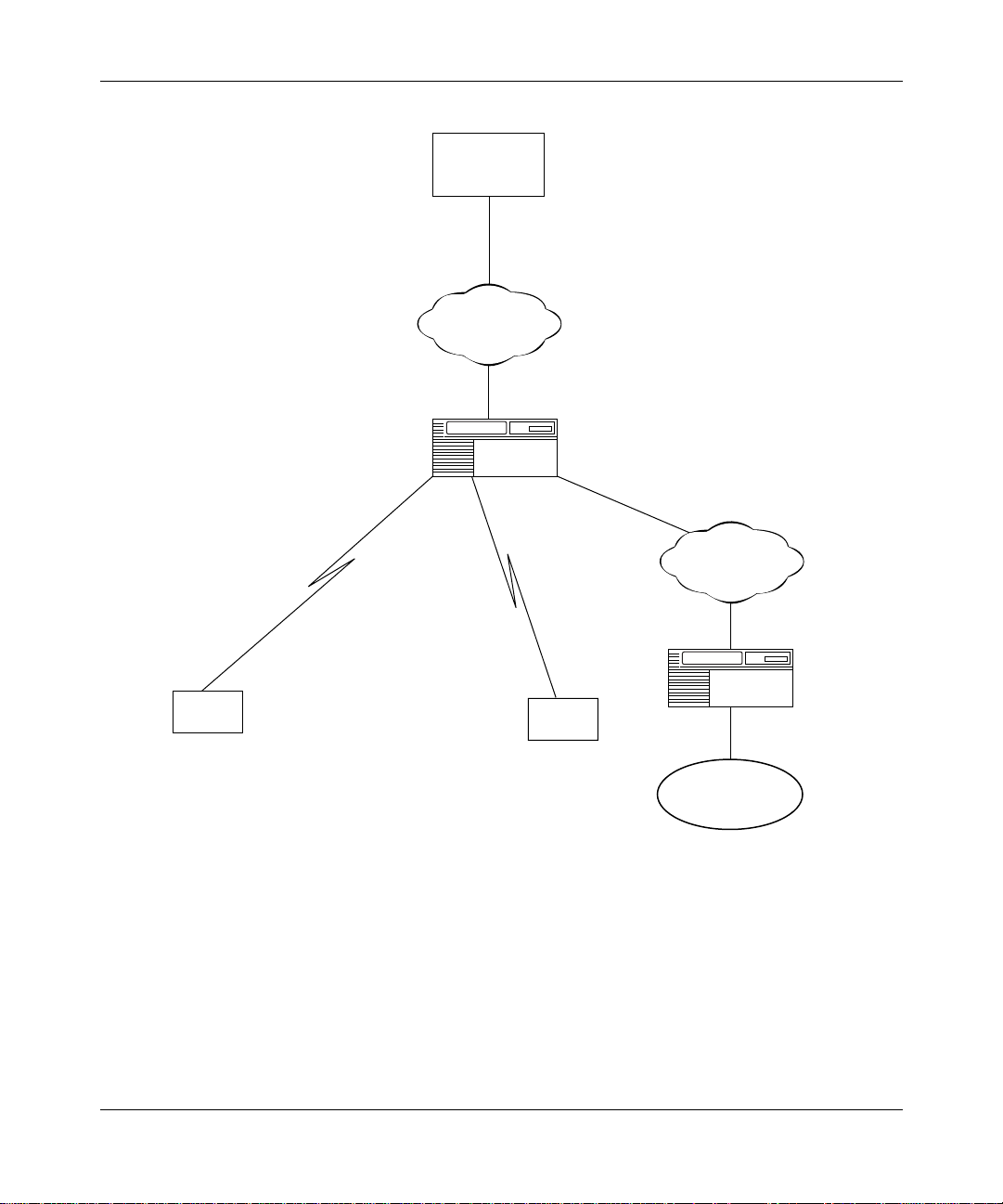
Figure 1-1
configuration with multipr otocol traffic to other locations.
Bay Networks pro vides two w ays to communicate di rectly wi th an S NA p rocessor
(such as an IBM 3745 or AS/400) over Frame Relay:
• Boundary Network Node (RFC 1490)
• Boundary Access Node
illustrat es the c onnec tion of a host th rough a F rame Re lay netw ork, i n a
Boundary Network Node (RFC 1490)
The Boundary Network Node (BNN) refers to RFC 1490, Routed SNA over
Frame Relay. This implementation of LLC2 also complies with the Frame Relay
Forum 3 (FRF.3), “Multiple Protocol Encapsulation over Frame Relay
Implementation Agreements,” which defines how SNA traffic traverses a Frame
Relay network.
BNN allows native SNA traffic (originating from SDLC LAN- or WAN-attached
devices) to communicate over public or private Frame Relay networks directly
with an SNA processor. Devices can communicate with int ermedia te routing
nodes or in a single-switch configuration function as a Frame Relay Access
Device (FRAD).
303533-A Rev 00
1-3
Page 20

Configuring LLC Services
Since BNN does not carry the destination and source MAC addresses in the
network packets, the BNN format carries the fewest number of bits per packet and
yields low ne twork ov erhead. Therefo re, you must expli citly define the permanent
virtual circuit ( PVC) to carry the packet to its destination. You do this with the
LLC2 Frame Relay Mapping Table. The mapping table consists of three fields:
• DLCI
• Remote (or Destina tion) MAC
• Local (or Source) MAC
Each entry requires that you spe ci fy the Remote MAC, Local MAC, or both. A
packet that matches this entry is then forwarded to the specified DLCI.
Bay Networks routers sel ect BNN when you configure the Frame Relay network
without source route encapsula tion.
Boundary Access Node
The Boundary Access Node (BAN) is an IBM router enhancement. B AN refers to
the RFC 1490 specification for Bridged SNA over Frame Relay. The associated
IBM NCP 7.3 enhancement is called the Boundary Node Identifier (BNI).
1-4
Since BAN carri es the destination and source MA C addr esses in the network
packets, this format carries more bits per packet.
Standard BAN use s the Source Route Bridg e frame format with loc al termin ation.
Bay Networks routers sel ect BAN when you configure the Frame Relay net work
with source route encapsula tion.
303533-A Re v 00
Page 21
Logical Link Control Overview
Host
Frame Relay
network
Single-switch
DLSw
Bay Networks
router
DLSw
TCP/IP
Client
303533-A Rev 00
Client
Figure 1-1. Sample Frame Relay Network
Bay Networks
router
Token Ring
DLS0007A
1-5
Page 22
Configuring LLC Services
LLC 8802/802.2 Standards
The LLC protocols comply with the CCITT 8802.2 standar d, a nd operate within
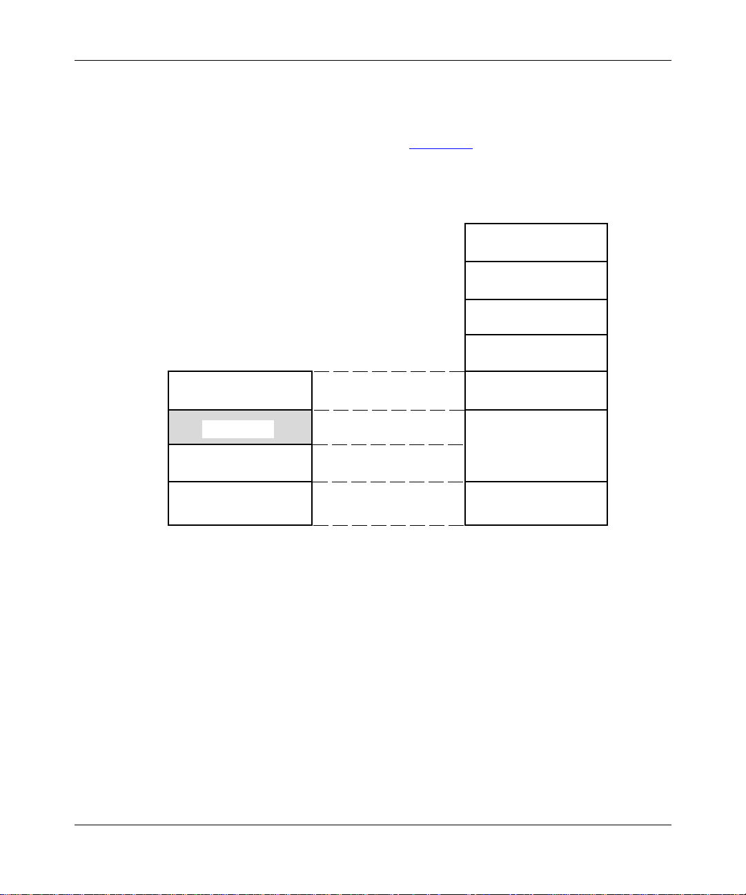
the IEEE Project 802.x protocol sta ck. Figure 1-2 compares LLC’s location in the
802.x protocol sta ck to its equivalent position in the ISO/OSI model.
ISO/OSI Model
Application
Presentation
Session
IEEE 802 Model
802.1
802..2 (LLC)
MAC
Physical
Figure 1-2. The LLC Sublayer in the IEEE 802.x and OSI Models
You can add an IEEE 802.2-compliant LLC interface to any physical circuit
attached directly to a n 8802.x/802.x LAN segment. Each interface services
higher-level clients (net wor king protocols and applications) and is serviced by
lower -le v el prot ocols (media access contr ol [MA C ] and physical la yers) operating
within the router.
LLC Service Classes
Transport
Network
Data Link
Physical
LLC0002A
1-6
The 802.2/LLC recommendations support three service classes:
• Connectionless Unacknowledged (Class 1 or LLC1)
303533-A Re v 00
Page 23

• Connection-Oriented (Class 2 or LLC2)
• Connectionle ss Acknowledged (Class 3 or LLC3)
Bay Networks LLC does not support the LLC3 service clas s.
Note:
LLC1 (Connectionless Service)
LLC1 is a data gram s ervice that sends and r ecei v es LLC f rames c alle d link s ervic e
data units (LSDUs) without requir ing acknowledgment from the peer to assur e
delivery.
LLC1 supports all forms of communication (point-to-point,
multipoint/mult icast, and broadcast).
This service is appropriate for protocols that provide addressing, routing,
recove ry, and sequencing services at a higher layer.
Logical Link Control Overview
LLC2 (Connection-Oriented Service)
LLC2 secures a point-to-point virtual circuit connection between link service
access points (LSAPs). The LLC2 protocol
• Responds to a request from a higher-level protocol to open a connection
through the datalink laye r
• Notifies a higher-level protocol that a co nne ct ion thr ough the datalink layer
has been established succ essfully
• Enables a higher-level protocol to
-- Send or receive LSDUs over an established datalink-layer connection
-- Sequence LSDUs sent over a datalink-layer connection
-- Control the flo w of LSDUs over a datalink-layer connection
The LLC2 service also
• Responds to a reque st from a higher-l evel protocol to reset a connection to its
initially connected state
303533-A Rev 00
1-7
Page 24

Configuring LLC Services
• Responds to a request from a higher-level protocol to close an established
connection
• Notifies a higher-level protocol that a co nne ct ion previously established has
been closed successfully
Because the connection occurs in the datalink layer rather than in higher layers,
LLC2 performs frame sequencing, flow control, and error recovery services for
the datalink layer.
LLC Operation Types
LLC supports two operation types:
• Unnumbered, Unacknowledged (Type 1)
• Numbered, Acknowledged (Type 2)
LLC1 supports only Type 1 operations; LLC2 supports both Type 1 and Type 2
operations.
Type 1 Operations
Type 1 operations have the following characteristics:
• LLCs exchan ge protocol data units (PDUs) without establishing a datalink
connection.
• The peer does not acknowledge the PDUs it receiv es.
• There are no mechanis ms for PDU sequenci ng, f low control, or error
recovery, because higher-level protoco ls perfo rm thes e serv i ce s.
Type 2 Operations
Type 2 operations have the following characteristics:
• The LLC and its peer must e stablis h a da tali nk-lay er vir tual c ircuit/ connecti on
prior to any excha nge of data.
• The source and destination are peer LLCs in an asynchronous, balanced
datalink connection.
1-8
303533-A Re v 00
Page 25

• The source and desti nat ion LLCs control traffic by means of a numbering
scheme for t he sequential transfer of PDUs. The PDUs for each virtual cir cuit/
connection ha ve independent sequence-n umbering schemes.
• The destination LLC acknowledges data PDUs that the sourc e LLC sends by
informing the source LLC of the next sequence number expected.
LLC Functionality
The LLC sublayer can support multiple logical links concurrently. The LLC
protocols generat e and inte rpret command packets or frames called protocol data
units (PDUs), which Table 1-1 describes. The LLC sublayer
• Initia tes and terminates control signal inte rchange with the XID, TEST,
SABME, and DISC PDUs.
• Organizes data flow with the U, I, and UA P DUs. The level of organization
differ s between T ype 1 and Type 2 operations.
• Interpr ets command PDUs it receives , and generate s appropriate response
PDUs, which differ between T ype 1 and Type 2 operations and LLC1 and
LLC2 service.
Logical Link Control Overview
303533-A Rev 00
• Manages error control and recovery with the REJ, RR, RNR, and FRMR
PDUs.
Table 1-1
lists Type 1 and Type 2 command PDUs and their counte rpart response
PDUs:
• Type 1 operations do not include definition of an Acknowledgment PDU.
• Type 2 operations do not include a command PDU cou nterpart for the FRMR
response PDU.
Table 1-1. LLC Command PDUs
Operation
Type Command Response
Type 1 Unnumbered Information (UI) No response
Exchange Identif ication (XID) Exchange Identificati on (XID)
Test (TEST) Test (TEST)
(continued)
1-9
Page 26

Configuring LLC Services
Table 1-1. LLC Command PDUs
Operation
Type Command Response
Type 2 Information (I) Informati on (I)
Receiver Ready (RR) Receiver Ready (RR)
Receiver Not Ready (R NR) Receiver Not Ready (RNR)
Reject (REJ) Reject (REJ)
Set Asynchronous Balanc ed M ode
Extended (SABME)
Disconnect (DISC) Disconnected Mode (DM)
No command Frame Reject (FRMR)
LLC Protocol Data Uni t Formats
The LLC protocol data unit (PDU) contains fields for addressing, control, and
data, as sho wn in Figur e 1-3. This section pr ovide s additi onal inf ormati on on each
field of the LLC PDU.
(continued)
Unnumbered Acknowledgment
(UA)
DSAP SSAP Control Information Field
8 bits 8 bits 8 or 16 bit s Variable; 8 bits each packet
Figure 1-3. LLC PDU Structure
Destination SAP (DSAP)
The DSAP Address field ident ifies one or more service access points (SAPs) for
which the LLC PDU is intended. The DSAP field contain s 7 bits of actual address
and 1 Address Desi gnation b it t o indicate an Indi vi dual ( I) dest ination addre ss or a
Group (G) destination addre ss, as shown in Figure 1-4.
1-10
303533-A Re v 00
Page 27

Figure 1-4. DSAP Address Field
• A value of 0 for the Address Des ignation bit indicates that the PDU is
destined for an individual SAP.
• A value of 1 for the Address Designation bit indicates that the PDU is
destined for a group-level SAP.
Source SAP (SSAP)
Logical Link Control Overview
Address designation bit
I/G D D D D D D D
LLC0003A
303533-A Rev 00
The SSAP Address field identifies the specific service access point tha t initiated
the PDU. The SSAP field contains 7 bits of act ual address and 1 Command/
Response Identifier bit to indicate tha t the LLC PDU is a Command (C) PDU or a
Response (R) PDU, as shown in Figure 1-5.
Command/response
identifier bit
C/R S S S S S S S
LLC0004A
Figure 1-5. SSAP Address Field
1-11
Page 28

Configuring LLC Services
• A value of 0 for the Command/Response Identifie r bit indicates that the PDU
is a Command PDU.
• A value of 1 for the Command/Response Identifie r bit indicates that the PDU
is a Response PDU.
SAP Addressing Scheme
All of the 802.2/LLC protocols provide a SAP addressing scheme that lets
multiple applic ations and protocol entities in a single machine share a MAC
address. Popular network protocols such as LAN Network Manager, NetBIOS,
and SNA all ha ve published SAP addresses, b ut any application can use a SAP to
send or receiv e data via the LLC sublayer. The LLC SAP function sorts frames
coming up from the MAC layer and directs them to the ap propriate applicatio n or
protocol softwa re ent ity.
Figure 1-6
illustrates some SAPs publishe d for Net BIOS and SNA. The xx
denotes all other publishe d and unpublished SAPs.
Applications
NetBIOS (Other)
(For LANattached
devices)
SAP SAP SAP SAP
F0 04 F4 xx
SNA
path
Control
(Used by
DLSw
and
APPN)
LAN
network
Managemt
LLC
MAC
LLC0005A
1-12
Figure 1-6. SAPs for LLC Clients
303533-A Re v 00
Page 29

Control Field
Logical Link Control Overview
SAP addresses can be
• Individual -- Designates a single SAP . The indi vidual address is usable as both
an SSAP and a DSAP. The individual SAP has an Address Designation bit
value of 0.
• Group -- Designates a group of DSAPs. The group DSAP has an Address
Designation bit v alue of 1.
• Global -- Designates a group consisting of a ll DSAPs that the underlying
MAC SAP addresses actively service. The global DSAP has a value of all 1s.
• Null -- Designates the SAP of the underlying MAC sublayer and does not
identify any SAP to the networ k la yer or any SAP to an associated layer
management function. The Null address is usable as both an SSAP and a
DSAP. The Null SAP has a value of all 0s.
The Control field consist s of one or two octe ts that designate command and
response functions. It also contains sequence numbers when required.
303533-A Rev 00
The format of the Control field of the LLC PDU de fines the type of operation
(Type 1 versus Type 2):
• Information (an I format PDU)
• Supervisor y (an S format PDU)
• Unnumbered (a U format PDU)
Figure 1-7
shows the three Contro l field formats.
1-13
Page 30

Configuring LLC Services
I format PDU
Information Transfer
Commands/Responses
Bit
8
7
5
6
4321
8-2
1
N(S) 0 N(R) P/F
S format PDU
Supervisory
Commands/Responses
U format PDU
Unnumbered
Commands/Responses
X XXX S S
M M M P/F MM 1 1
Key
N(S) Send Sequence Number
N(R) Receive Sequence Number
S Supervisory function bit
M Modifier function bit
X Reserved and set to zero
P/F Poll/Final bit
Figure 1-7. LL C PDU C on t rol Fie ld Format
0 1 N(R) P/F
LLC0006A
Control Field Formats
Table 1-2 further defines the purpose of the three PDU types, where the specific
format in the PDU Control fie ld determines the type.
1-14
303533-A Re v 00
Page 31

Logical Link Control Overview
Table 1-2. PDU Form at and Funct i on
Format Function
Information
Transfer
Format (I)
Supervisory
Format (S)
Unnumbered
Format (U)
The I format PDU performs a numbered information transfer in Type
2 operation. Except for the UI, TEST, FRMR, and XID command/
response PDUs, th e I format PDU is the only LLC PDU that can
contain an Information field. (Refer to “Information Field
chapter for more details .)
The S format PDU perf orms datal ink supervi sory control fu nction s in
Type 2 operation, such as acknowledging I format PDUs, requesting
retransmission of I format PDUs, and requesting a temporary
suspension of tr ansmission of I format PDUs.
The U format PDU is available f or Type 1 or Ty pe 2 operations, and
provides additional datali nk control functions and unsequenced
informati on transfer.
” later in this
Table 1-3 further defines the purpose of parameter bits in the PDU Control field.
Table 1-3. Control Field Bits and Functions
Bit Function
Send
Sequence
Number N (S)
Bit
Only I PDUs contain N(S), which is the sequence number of the PDU
being transmitted.
303533-A Rev 00
Receive
Sequence
Number N (R)
Bit
Poll/Final
(P/F) Bit
I PDUs contain N(R), which is the sequence number of the PDU an
LLC expects to receive next on the specifi ed datalink connecti on.
The P/F bit solicit s (polls) a response from the addressed LLC. The
Final (F) bit in dicat es the resp onse PDU sent as a res ult of a so lici ting
(poll) command.
1-15
Page 32

Configuring LLC Services
Table 1-4 further defines the purpose of each command and response PDU.
Table 1-4. Comm and Names and Definiti ons
Command/
Response
Control
Field
Value Definition
Unnumbered
Informati on (UI)
Exchange
Identification
(XID)
Test
(TEST)
Information (I) 6xxx0
0x13
or
0x03
0xBF
or
0xAF
0xF3
or
0xE3
or
xx even
Transports information to one or more LLCs. Since this
is a Type 1 operation, there is no corr esponding
response/reply PDU.
The XID comma nd PDU conveys to the destination LLC:
• The types of LLC services the source LLC supports
• The receive window size the source LLC supports
per datalink connection (per virtual circuit)
The XID response PDU identif ies the responding LLC
and conv eys to the source LLC:
• The types of LLC services the destination LLC
supports
• The receive window size the dest ination LLC
supports per datalink connection (per virtual circuit)
The TEST command PDU causes the destination LLC
to respond with the TEST resp onse PDU; i t performs a
loopback test of the LLC-to-LLC transmission paths.
The TEST command PDU also initiates the
establi shm ent of an LLC1 logical link acr oss a network
to another LLC entity.
The TEST response PDU confirms the estab lishment of
an LLC1 link.
The I command PDU indicates t o the destination LLC:
• The sequence number for each I command PDU
• The I PDU sequence number the destination LLC
expects next
The I command PDU also serves as an I respon se PDU
by indicating to the de stination LLC that the source LLC
has received I PDUs up to a designated number f rom
that destina ti on LLC.
1-16
(continued)
303533-A Re v 00
Page 33

Logical Link Control Overview
Table 1-4. Comm and Names and Definiti ons
Control
Command/
Response
Receiver Ready
(RR)
Receiver Not
Ready
(RNR)
Reject
(REJ)
Set
Asynchronous
Balanced Mode
Extended
(SABME)
Field
Value Definition
01xx The RR comman d PDU indicates that the source LLC is
ready to r eceive an I PDU. The sending LLC then
considers I PDUs sent prior to the RR condition as
ackno wledged.
05xx Th e RNR command PDU notifies the destination LLC
that the originat ing LLC is busy and temporari ly unable
to receive I PDUs. RNRs, combined with RRs, control
flow between source and destination LLC interfaces.
09xx The REJ command PDU conveys a request to the peer
LLC to retransmit I PDUs, starting with the I PDU that
the REJ command design ates.
7F
or
6F
The SABME command PDU establishes an LLC2
connection to the destination LLC. The connection
operates in asy nchronous balanced mode.
If the destinati on LLC receives from its network layer a
DataLink Connect request, the destination LLC
responds to the SABME PDU with a UA PDU. If the
destinati on LLC receives from it s network layer a
DataLink Discon nect request, it does not send a UA
PDU.
(continued)
303533-A Rev 00
Disconnect
(DISC)
53
or
43
The DISC response PDU closes an open connection by
initiating a SABME command. The DISC PDU inf orms
the destinat ion LLC that the source LLC is suspe nding
the datalink conn ection , and the destinati on LLC should
assume the Disconnected Mode.
Prior to acting on the DISC command, the destination
LLC must confirm the acceptance of t he DISC
command PDU by sen ding a U A r esponse PDU. I PDUs
sent previ ously but not acknowledged remain
unackno wledged.
(continued)
1-17
Page 34

Configuring LLC Services
Table 1-4. Comm and Names and Definiti ons
Control
Command/
Response
Unnumbered
Acknowledg- me
nt
(UA)
Disconnected
Mode (DM)
Fr ame Reject
(FRMR)
Field
Value Definition
73
or
63
1F
or
0F
97
or
87
The UA resp onse PDU acknowledges the receipt and
acceptance of a SABME or DISC command PDU
relating to a specific datalink connection to be opened
or closed, as appr opriate for the t ype of command PDU
it has received.
The DM response PDU indicates that the LLC sending
the response is logi cally disconnected from the datali nk
connection.
The FRMR command PDU reports to the sending LLC
that an uncorrectable condition was detected in a
received frame. The FRMR PDU includes an
information field that indicates the reason for the PDU
rejection.
The LLC receiving the FRMR PDU
• Initiates the appropriate mode setting
• Initiates corrective action by reinitializing
transmission in both directions on the datali nk
connection, using the SABME and DISC command
PDUs, as appr opriate
(continued)
Information Field
The contents of the Informati on f ield depend on the type of PDU in which it
appears, as follows:
• The Informati on field of an I format PDU contains only user data.
• The Infor mation field of a UI command/response P DU also contai ns only use r
data.
• The Informati on field of a TEST command/response PDU is optional and
contains a te st pattern used for LLC loopback testing.
• The Informati on field of an XID command/response PDU contains
-- An 8-bit XID format identif ier field
-- A 16-bit parameter fie ld encoded to identify the LLC services supported,
1-18
plus the maxim um receive window size
303533-A Re v 00
Page 35

Logical Link Control Overview
• The Informati on field of an FRMR PDU contains the reason for PDU
rejection b y an LLC. (The contents of the Informati on f iel d of an FRMR PDU
is beyond the scope of this publication. For more details on the FRMR PDU,
refer to the ISO 8802/IEEE Std 802.2 1989.)
For More Information about Logical Link Control
The followin g publications give technical details on 802.2/Logic al Link Control,
Token Ring LANs, DLSw, APPN, IBM LAN Network Manager, and LNM
Servers:
• Institute of Electrical and Electronics Engineers. International Standard ISO
8802-2/ANSI/IEEE Std 802.2 1989. Information Processing Systems, Local
Area Networ ks, Part 2: Logical Link Control. Washington, D.C., 1989.
• IBM Corporation, SC30-3374-02. IBM Token Ring Network Architecture
Reference. 3rd ed. September 1989.
• IBM Corporation, 31G6962. IBM LAN Network Manager User’s Guide.
• Perlman, Radia. Interconnections: Bridges and Router s. Reading,
Massachusetts: Addison- Wesley Publishi ng Compan y, 1992.
303533-A Rev 00
1-19
Page 36

Page 37

LLC2 Routed over Frame Relay
LLC2 (connection-oriented servic e) in a Bay Networks router supports Frame
Relay with both Data Link Switching (DLSw) and Advanced Peer-to-Peer
Networking (APPN), based on RFC 1490.
Compatibility with RFC 1490
RFC 1490 describes an encapsulation method for carrying internetworking traffic
over a Frame Relay backbone . The description cove rs both bridging and routing
standards.
Chapter 2
The Bay Networks router implementation of LLC exceeds RFC 1490 (SNA
encapsulation in Frame Rela y only) by complying with the Frame Relay Forum’s
“Protocol Encapsulation over Frame Relay Implementation Agreements.” The
latter descri ption not only de f ines ho w route d SN A traff ic traverses a Frame Relay
network, but also adds RFC 1490 support for Frame Relay to DLSw and APPN.
This feature allo ws native SNA traff ic originating from SDLC-, Token Ring-, or
Ethernet-atta ched devices to communicate over public or pri vate Frame Relay
networks directl y with IBM 3745 or 3746 communicati ons contr oller s. It oper ates
on all Bay Networks routers that inc lude a Frame Relay interface. Devices can
communicate with intermediate routing nodes or in a single -switch configuration
similar to a standalone Fra me Relay Access Device (FRAD).
Compatibility with IBM NCP 7.1 and Higher
LLC2 routed ove r Frame Relay is fully compatibl e wit h IBM NCP 7.1 and higher ,
and with existing or new IBM equipment. The service has passed IBM
interoperability testing. You can use it without upgrading your LAN-based
downstre am physical units (DSPUs) or network type, such as APPN or IP.
303533-A Rev 00
2-1
Page 38

Configuring LLC Services
DSPUs attached to the rout er retain full visibility for IBM NetView management.
The router passes through al l NetView commands for the DSPUs and any Alerts
generated by the DSPUs.
You can configure a network without a router at the host, if the communications
controller is di rectly attached to a Frame Relay net work. Some terminals can also
connect directly to the Frame Relay network without a router. Frame Relay
networks save the expense of leased lines. Additional savings accrue because one
port on a communications control ler can supp ort hundr eds of data link connec tion
identifiers (DLCIs).
Bay Networks interoperates with NCP 7.1 and higher with software only,
eliminating the need for any new hardware or upgrades to existing SNA terminals
or router equipment.
Figure 2-1
illustrates the conne ction of an SNA host through a Frame Relay
network in a configuration with multiprotocol traffic to other locations. LLC can
also route SDLC and Ethernet traffic, in addition to APPN, Token Ring, and IP
traffic.
2-2
303533-A Re v 00
Page 39

LLC2 Routed over Frame Relay
SNA host
IBM Communications
controller with NCP
(No router required)
Frame Relay
network
Bay Networks router
with DLSw or APPN
Token Ring
Figure 2-1. Sample Frame Relay Network Using LLC2
IPAPPN
LLC007A
303533-A Rev 00
2-3
Page 40

Configuring LLC Services
FRAD-like Functionality
Token Ring, Ethernet, and SDLC endstations communicate with a Frame Relay
attached host via Frame Relay Access Devices (FRADs). The Bay Networks
router with DLSw operating in single - switch mode has FRAD-like capability,
supporting Token Ring, Ethernet, a nd SDLC en dstations. The router performs the
following a ctions:
• Terminates the Data Link Control level sessions
• Strips the link- level header off the SNA packet
• Puts an RFC1490 LLC header on the SNA packet
• Sends packets into the Frame Relay network
Mapping DLCIs to MA C Ad d resses
The Frame Relay n etwor k pro vides a number of p ermanent vir tual circuit s (PVCs)
that form the basis for connections between devices attached to the same Frame
Relay network. Each virtual circuit is uniquely identified at each Frame Relay
interface by a DLCI. The Frame Relay interface allows either group or direct
(single) assign ment of DLCIs. Group assignment allows many DLCIs per circuit;
direct assignment allows only one.
2-4
The system administrator or Frame Relay provider assigns DLCIs. To
communicate with an IBM host, you must associate the MAC address of your
DSPU with a DLCI. You can accomplish this task in one of two ways:
• Create a virtual MAC address, formed by preceding the DLCI address, such
as 100 (decimal), with a unique mask, such as 0x400000F F, to make a valid
MAC address, for exa mple, 400000FF0064. (Decimal 100 is 64
hexadecimal.)
When the router receives an LLC frame from the DLSw network with a
destination MAC (dmac) starting with the virtual MAC mask, it can
automatically tr anslate it into a DLCI, so no mapping table is needed at the
Frame Relay interface.
• Use the endsta tion’s physical or locally co nfi gured MA C ad dress. I n this case ,
be aware that if you change your hard ware or endstation configur ation, you
have to reconfigure the DLCI mapping table.
303533-A Re v 00
Page 41

When the router r eceives a n LLC frame from the DLS w network with a dmac
not starting with th e virtual MA C mask, the mapping tabl e at the Frame Relay
interface translates the dmac into a DLCI.
SDLC single switc hed over LLC does not require address mapping if a virtual
MAC address is used to access the host. But you still have to define DLCIs.
Usually you c onfigure only the remote MAC in the mapping table, setting it equa l
to the remote host MAC address. (A host may be an IBM mainframe.) You must
configure the local MAC in the map p ing ta ble only i f the Fra me Relay interfac e
receiv es connection requests. Usually only local (workstation) nodes will request
a connection, so you configure only the remote MAC address.
Router Mapping Examples
Some sample network configurations with associated mapping tables follow,
including:
• Virtual MAC to Frame Relay
LLC2 Routed over Frame Relay
• Frame Relay to Virtual MAC
• Physical MAC to Frame Relay
• Frame Relay to Physic al MAC
• Frame Relay to Frame Relay
Although these networ k configurations illustrate topologies with two r outers, the
same principles apply for DLSw operating in single-switch mode. Instea d of
configuring a single interface on each router, you configure two interfaces on a
single router.
303533-A Rev 00
2-5
Page 42

Configuring LLC Services
Virtual MAC to Frame Relay
Figure 2-1 illustrates a sample virtual MAC address to Frame Relay DLCI
mapping. In this ill ustration, th e PC make s connec tion requests to Host 1 a nd Ho st
2. The worksta tion administrator has control over the PC configuration and has
configured the remote host addresses as virtual MAC addresses corresponding to
the DLCIs assigned to the hosts. Configuring the PC in this way simplifies the
router configuration because a mapping ta ble is not necessary in the Frame
Relay-attache d Router B. The connectio n request r ecei v ed at Router A will ha ve a
source MAC address of the PC MAC and a destination MAC address of Remote
Host 1 or 2.
Host
Frame Relay
network
2-6
Single-switch
Client
DLSw
Bay Networks
router
DLSw
Client
Table 2-1. Virtual MAC to Frame Relay Topology
TCP/IP
Bay Networks
Token Ring
router
DLS0007A
303533-A Re v 00
Page 43

Frame Relay to Virtual MAC
Figure 2-2 illustrates a sample Frame Relay DLCI to virtual MAC address
mapping. In this network, Host 1 and Host 2 can make connec tion requests to the
PC. The workstation administrator has control ov e r the PC configuration and has
configured the remote host addresses as virtual MAC addresses corresponding to
the DLCIs assigned to the hosts.
At Router B, a mapping table maps the Host 1 and Host 2 DLCIs to the PC MAC
address. Router B first creates a connection request with the source MAC
addresses equal to the vir tual MAC address corresponding to the Host 1 and Host
2 DLCIs. Router B then creates a connection reque st with the destination MAC
equal to the local MA C address from the mapping table.
Router B always se ts the sou rce M AC address equ al to the virtu al MAC add res s,
eve n if there is a remote MAC address configured in the mapping table.
Configuration at PC:
Remote Host 1: 400000FF0064 (64 Hex = 100 Decimal)
Remote Host 2: 400000FF0065 (65 Hex = 101 Decimal)
PC MAC: 400000000003
LLC2 Routed over Frame Relay
303533-A Rev 00
PC
Source MAC (smac) = virtual
Destination MAC (dmac) = 400000000003
Token Ring
DLSw
Router A
Connection request
Mapping Table for Router B
Remote MAC Local MACDLCI
100
101
Figure 2-2. Frame Relay to Virtual MAC Topology
DLCI 100
Frame Relay
Router B
400000000003
400000000003
Host 1
Host 2
DLCI 101
LLC0009A
2-7
Page 44

Configuring LLC Services
Physical MAC to Frame Relay
Figure 2-3 illustrates a sample physical MAC address to Frame Relay DLCI
mapping. In this networ k, the PC makes c onnection r equests to Host 1 and Host 2.
The workstation administrator does not have control over the PC configuration
and must use a configurat ion with r eal, physical MAC addresses for the remote
hosts.
At Router B, a mapping table maps Host 1 and 2 to the DLCIs assigned to the
hosts. The connection request receiv ed at Router A will have the source MAC
address of the PC MAC, and a destination MAC address of Remote Host 1 or 2.
Configuration at PC:
Remote host 1: 400000000001
Remote host 2: 400000000002
PC MAC: 400000000003
PC
Token Ring
DLCI 100
Host 1
Frame Relay
2-8
DLSw
Router A
Connection request
Mapping Table for Router B
Remote MAC
Source MAC (smac) = PC MAC
Destination MAC (dmac) = Remote host 1 or 2
400000000001
400000000002
Figure 2-3. Physical MAC to Frame Relay Topology
Router B
Local MAC
Host 2
DLCI 101
DLCI
100
101
LLC0010A
303533-A Re v 00
Page 45

Frame Relay to Physical MAC
Figure 2-4 illustrates a sample Frame Relay DLCI to Physical MAC mapping. In
this network, Host 1 and Host 2 can make connection requests to the PC. The
workstation administrator doe s not have control over the PC configuration and
must use a configuration with real, physical MAC addresses for the remote hosts.
Router B requires a mapping table to map the Host 1 and Host 2 DLCIs to the PC
MAC address. Router B creates a connection request with the sour ce MAC
address equal to the virtual MAC address corresponding to the Host 1 a nd Host 2
DLCIs. Router B also creates a connection r equest with the destination MAC
address equal to the local MAC address from the mapping table.
Router B always se ts the sou rce M AC address equ al to the virtu al MAC add res s,
eve n if there is a remote MAC address configured in the mapping table.
This mapping does not work with applications that check the source
Note:
MAC address ag ainst configured remote host addre sses.
LLC2 Routed over Frame Relay
303533-A Rev 00
2-9
Page 46

Configuring LLC Services
Configuration at PC:
Remote host 1: 400000000001
Remote host 2: 400000000002
PC MAC: 400000000003
PC
Source MAC (smac) = virtual
Destination MAC (dmac) =
Token Ring
Router A
400000000003
Figure 2-4. Frame Relay to Physical MAC Topology
Frame Relay to Frame Relay
Figure 2-5 illustrates a samp l e Fra me Rel ay DLCI-to-Frame Relay DL CI
mapping. In this network, the PC makes connection requests to both Host 1 and
Host 2. The workstation administrator has configured the P C with Remote Host 1
and Remote Host 2 equal to the assigned DLCIs. Router A require s a mapping
table to map Remote Host 1 and 2 DLCIs to a virtua l MA C address corresponding
to Host 1 or Host 2 DLCI.
DLSw
Connection request
Mapping Table for Router B
Remote MAC
DLCI 100
Frame Relay
Router B
Local MAC
400000000003
400000000003
Host 1
Host 2
DLCI 101
DLCI
100
101
LLC0011A
2-10
Router A creates a connection request with the source MAC address equal to the
virtual MAC address corresponding to the Remote Host 1 or 2 DLCI. Router B
creates a connection reque st with the destination MAC address equal to the local
MAC address from the mapping table.
303533-A Re v 00
Page 47

LLC2 Routed over Frame Relay
Router A always sets the sour ce MAC address equal to the virtual MAC address,
eve n if there is a remote MAC address configured in the mapping table.
Remote host 1 = DLCI 102
Remote host 2 = DLCI 103
DLCI 100
(100 decimal =
PC
Token Ring
64 hex)
Frame Relay
Host 1
Host 2
DLSw
Router A
Mapping Table for Router A
Remote
102
103 400000FF0065
Local MACDLCI
400000FF0064
Source MAC (smac) = virtual
Destination MAC (dmac) = 400000FF0064
or 400000FF0065
Router B
No mapping
Figure 2-5. Frame Relay-to-Frame Relay Topology
DLCI 101
(101 decimal =
65 hex)
LLC0012A
303533-A Rev 00
2-11
Page 48

Configuring LLC Services
LLC2 over Frame Relay: Routed versus Bridged
Figure 2-6 illustrates (a) SNA over Frame Rel ay with source-route bridging and
(b) SNA over Frame Relay in native mode, inc luding routing through SDLC and
Ethernet. The Frame Relay li nk can be part of an alt ernate rou te to the Token Ring
or other link. Dotted lines indicate the path of LLC, which is passed through
bridging but te rminated at the router for more flexible routing.
RFC 1490 bridging standard
SNA mainframe
RFC 1490 routing standard
SNA mainframe
Frame Relay
network
Router (encapsulates
Data in FR headers)
SR over FR
Token Ring
Token Ring
(a)
LLC
IBM 3745
Communications
controller
running NCP
Router (removes
FR headers)
End station
Frame Relay
network
SDLC
To remote sites
Token Ring
IBM 3745/6
Communications
controller
running NCP 7.1
or higher
Bay Networks router
with single-switch DLSw
Operating as FRAD
Ethernet
LLC
End station
(b)
LLC0013A
2-12
Figure 2-6. RFC 1490 Bridging and Routing Standards for SNA
303533-A Re v 00
Page 49

LLC2 Routed over Frame Relay
For More Information about LLC2 over Frame Relay
The followin g publications give technical detail on LLC2 over Frame Relay .
Bradley, Terry; Brown, Caralyn; and Malis, Andrew G. “Multiprotocol
Interconnect o ver Frame Relay,” RFC 1490, Wellfleet Communications and
Ascom Timplex, Inc., July 1993.
Rao Cherukuri, e d. “Multiprotocol Encapsulation Implementation Agreement,”
FRF.3, Frame Relay Forum.
303533-A Rev 00
2-13
Page 50

Page 51

Chapter 3
Enabling LLC Services
This chapter desc ribes how to enable LLC services. It as sumes tha t you have read
Configuring and Managing Routers with Site Manager and that you have
completed the follo wing steps:
1. Opened a configuration file
2. Specified r outer hardware if this is a local mode conf iguration file
3. Selected the connector on which you are enabling LLC
When you enable LLC over Frame Relay with APPN and DLSw networks, you
must specify the Frame Relay mapping parameters yourself, while the
Configura tion Manager sets default v alues for all the rest. If you want to modify
LLC parameters, refer to Chapter 4. See Appendix A for a quick reference to the
default LLC parameter settings.
Using the Parameter Descriptions
Each LLC param et er description provides information about default setting s,
valid parameter options, the parameter function, inst ructions for setting the
parameter, and the Management Information Base (MIB) object ID.
The Technician Interface allows you to modify parameters by issuing
commit
modifying parameters using Site Manager. For more information about using the
T echnician Interface to access the MIB, refer to Using Technician Interface
Software.
commands with the MIB object ID. This process is equivalent to
set
and
303533-A Rev 00
3-1
Page 52

Configuring LLC Services
Caution:
The Technician Interface does not verify tha t the value you enter fo r
a parameter is valid. Entering an invalid value can corrupt your configur ation.
Enabling LLC2 on an Interface
To enable LLC2 on an interface, select LLC2 from the Select Protocols window
(Figure 3-1).
3-2
Figure 3-1. Select Protocols Window (LLC only)
This menu appears after you select a link or network module connector to which
you are configur ing LLC2. For other than Frame Relay configurations, you need
not specify any additional configuration information. The system software
provides def ault LLC2 servic es. To change the operating par ameters of the defa ult
service, refer to Chapter 4.
303533-A Re v 00
Page 53

Enabling LLC Services
Enabling LLC2 Ser vices over Native Frame Relay
If you are configuring and enabling Frame Relay on LLC2 media, Configuration
Manager displays a set of screens that allow you to start LLC2 and related
services such as APPN and DLSw. Perform the following steps.
Select Frame Relay from the WAN Protocols me nu (Figure 3-2).
1.
Click on OK.
2.
303533-A Rev 00
Figure 3-2. WAN Protocols Wind ow ( Fram e Relay)
The Select Protocols window appears (Figure3-3).
3-3
Page 54

Configuring LLC Services
Figure 3-3. S elect Protocols W i nd ow
For APPN Networks
Select APPN from the Select Protocols win dow.
1.
The Configuration Manager automatically selects LLC2 as w ell.
Click on OK.
2.
The Source Route Encapsulation dialog box appears (Figure 3-4
Figure 3-4. Source Route Encapsulation Dialog Box
3-4
).
303533-A Re v 00
Page 55

Select Cancel.
3.
This selects nati ve (routed) Frame Relay for LLC2.
In the APPN Local Node Name Configuration window, specify the APPN
4.
Local Node Name parameter and click on OK.
When the APPN /FR Con figuration window appears, specify the DLCI
5.
and SAP parameters and click on OK.
Refer to Configuring APPN Services for information.
For DLSw Networks
Select DLSw from the Select Protocols win dow.
1.
Specify the IP Virtual Ring parameter in the DLSw Global Parameters
2.
window. Click on OK.
Refer to Configuring DLSw Services for information.
In the Source Route Encapsulation dialog box (Figure 3-4), click on
3.
Cancel.
Enabling LLC Services
303533-A Rev 00
The LLC2 Frame Relay Mappings window appears (Figur e 3-5
).
3-5
Page 56

Configuring LLC Services
Figure 3-5. LL C 2 Fram e R elay Mappings Wi ndow
3-6
Select Add .
4.
The LLC2 Frame Relay Mapping Add window appears (Figure 3-6
).
303533-A Re v 00
Page 57

Figure 3-6. LL C 2 Fram e R elay Mapping A dd W i nd ow
Enabling LLC Services
Specify the DLCI, Remote MAC, and Local MAC parameters, as follows:
5.
Parameter : DLCI
Default: None
Options: Standard Data Link Connection Identifier numbers
Function: Provides the number of the virtual circuit to which you are mapping the
local or remote MA C address.
Instructions: Enter a decimal DLCI number assigned by your system administrator or
Frame Relay provider.
MIB Object ID: 1.3.6.1.4.1.18.3.5.1.6.9.1.3
303533-A Rev 00
3-7
Page 58

Configuring LLC Services
Parameter: Remote MAC
Default: None
Options: Standard MSB Token Ring MAC addresses
Function: Provides the remote MAC address, mapping outgoing requests to the
DLCI value. The remote MAC address must be unique, with only DLCI
mapping for a specif ic MAC address.
Instructions: If you need to specify the real hardware address of the host, enter it as an
octal string.
MIB Object ID: 1.3.6.1.4.1.18.3.5.1.6.9.1.5
Parameter: Local MAC
Default: None
Options: Standard MSB Token Ring MAC addresses
Function: This parameter provides the local MAC address, mapping incoming
requests on this DLCI to that address. The local MAC address must be
unique, with only DLCI mapping for a specific MAC address.
Instructions: If the incoming connections are valid, enter the MAC address of the
recipient.
MIB Object ID: 1.3.6.1.4.1.18.3.5.1.6.9.1.4
Click on OK.
6.
The Configuration Manager returns to the LLC2 Frame Relay Mappings
window sho wing the added circuit (Figure 3-7
3-8
).
303533-A Re v 00
Page 59

Enabling LLC Services
Figure 3-7. LLC2 Frame Relay Mappings Window with DLCI Added
Select Apply.
7.
Repeat Steps 4 through 6 for addition al mappings. If you are finished, selec t
Done. You return to the series of layered windows.
Fill in any subsequent DLSw layered windows.
8.
Refer to Configuring DLSw Services for information.
303533-A Rev 00
3-9
Page 60

Page 61

Chapter 4
Editing LLC Parameters
You can edit the parameters for the LLC interfaces that you configure on the
router.
To edit LLC parameters, you must first configur e at least one LLC
Note:
interface on the ro ute r. To co nfigu re an LLC interface, or to add additional
LLC interfaces, see Configuring and Managing Routers with Site Manager .
You can configure only one LLC2 interface per physical circuit with native
mode and source-route bridging; with routed Frame Relay, you can add more,
depending on your system’s resources.
303533-A Rev 00
When you configure an LLC2 interface on an 802.x LAN physical (LAN
attachment) circuit, you supply information required by the MAC and LLC
sublayers.
4-1
Page 62

Configuring LLC Services
Configuring LLC Parameters
To access and edit LLC parameters, begin at the Configura tion Manager window
(Figure 4-1) and select the Protocols > LLC2 menu path.
Figure 4-1. Configuration Manager Window
Alternatively, you can access LLC p arameter windows by highlig hting a circuit in
the Configuration Manager window, and then selecting Edit Circuit to in voke the
Circuit Definition window. This windo w is described in Configur ing and
Managing Routers wit h Site Manager. Use the LLC Circuit menu to access LLC
parameters.
You can select either LLC1 Circuit or LLC2 Circuit from either menu. If you
select LLC1 from the menu, the screen displ ays a list of interfaces that use LLC1
only (such as Source Routing Bridge) . If you select LLC2, the screen displays a
list of inte rfaces that requir e the services of LLC2 (such as APPN, DLSw, and the
LNM Servers ).
4-2
303533-A Re v 00
Page 63

Editing LLC2 Global Parameters
Only the Enable parameter is visible at the global (router) level for LLC. To
change the setting of the Enable parameter, be gin at the Configuration Mana ger
window (Figure 4-1) and proceed as follows:
Select Protocols > LLC2 > Global.
1.
Editing LLC Parameters
The Edit LLC2 Global Parameters window appears (Figure 4-2)
Figure 4-2. Edi t LL C2 Gl ob a l Paramet ers W in dow
Change the En a bl e para m e ter to Disa bl e if necessary.
2.
(Refer to the description of the Enable parameter, which follows this
procedure.)
Click on OK to save your change and exit the Edit LLC2 Global
3.
Parameters window.
.
303533-A Rev 00
4-3
Page 64

Configuring LLC Services
Parameter : Enable
Default: Enable
Options: Enable
Function: Globally enables or disables the system soft ware mechanisms that, in
Instructions: Select Disable to for ce ev er y LLC2 interface exist ing on this node into the
|
Disable
turn, allow (or do not allow) users to add an LLC2 interface to any 802.x
LAN physical circuit. You can configure only one LLC2 interface per
physical LAN circuit. Other significant actions the system software
performs when you choose a setting for the LLC Enable parame ter
include
Disable -- Fo rc es every LLC2 int erfac e on t his node into the inoperative
(down) state .
Enable -- R einitializes e very LLC2 interface on this node, with each
interface maintaining the most recent setting of its o wn int erface Enable
parameter. The actual operating sta te of each interface further depends on
the current up/down state of the associated physica l circuit.
inoperative (down) state.
Select Enable only when an existing LLC 2 interface is in the Disabled
state.
MIB Object ID: 1.3.6.1.4.1.18.3.5.1.6.1.2
Editing LLC2 Interface Parameters
Use the Configurat ion Manager to access and customize LLC2 interface
parameters for specific clients suc h as DLSw and LAN Network Manager. These
and other LLC2 clients may be configur ed on the same physical circuits and,
therefore, s hare t h e same L LC int er faces . In suc h case s , you can det erm ine a
compromise profile of LLC2 parameter settings that satisf y the combined
recommendations of the LLC2 clients.
To access and edit LLC2 interface parameters, begin at the Configuration
Manager window and proceed as follow s:
Select Protocols > LLC2 > Interfaces.
1.
The LLC2 Interface Configuration window appears (Figure 4-3)
4-4
.
303533-A Re v 00
Page 65

Editing LLC Parameters
303533-A Rev 00
Figure 4-3. LLC2 Interface Configuration Window
Use the scroll bar on the lowe r right of your screen to view more parameters,
including Frame Relay Virtual MAC Address Mask (Figure 4-4):
Figure 4-4. LLC2 Interface Configuration Window (Bottom)
4-5
Page 66

Configuring LLC Services
The LLC2 Interface Configuration window contains the followin g
information fields:
• The upper-left quarter contains a window that lists all LLC2 interfaces
• The lower-left quarter lists parameters you can alter to suit your network
• The lower-right quarter shows the current interface parameter values.
Select or highlight the interface you want to customize.
2.
The values in effect for that interface appear (lower right) in the parameter
value windows. (Click on Values to display the valid range of values for any
parameter.)
Edit those parameters you want to change.
3.
Use the descriptions fol lowing this procedure as a guide.
Click on Apply to sa ve your changes.
4.
Click on Done to exit.
5.
configured on physical circuits belonging to this node. This list does not
appear in the Edit LLC2 Interf ace window.
configura tion requirements.
4-6
You return to the original window.
Note:
Alternatively, from the Circuit Definition window, select Protocols or
Group Protocols > Edit LLC2 > Interface to display the Edit LLC2 Interface
window. This window has the same parameters as the LLC Interface
Configura tion window. The Edit LLC2 Interface window shows only the
circuit you hav e highlighted from the Circuit Def inition window. Refer to
Configuring and Managing Routers with Site Manager for information on
editing circuit s.
The LLC2 Interface Configuration window and Edit LLC2 Interface window
include the follo wing entries:
303533-A Re v 00
Page 67

Parameter : Enable
Default: Enable
|
Options: Enable
Disable
Function: Enables or disables the LLC2 interface added previously to this LAN
physical circuit.
Instructions: Select Enable if you disabled this LLC2 interfa ce previously and now
want to re-enabl e the i nte rface on its associated LAN physical circuit.
Select Disable if you want to disab le this LLC2 interface on its associated
LAN physical circuit.
MIB Object ID: 1.3.6.1.4.1.18.3.5.1.6.2.1.2
Parameter: Max Octets in UI
Default: 5128 (octets)
Range: 1 to 5128
Function: Specifies, in octets, the maximum size of an Unnumbered Information
(UI) PDU this LLC2 interface sends or receives.
Editing LLC Parameters
Instructions: Enter a valid value from 1 octet (8 bits) to 5128 octets. Choose a value
that is appropriate for the applications LLC2 supports.
The LLC sublayer imposes no restrictions. However, all MAC sublayers
must be capable of accommodating UI PDUs with Information fields up
to 128 octets in length.
MIB Object ID: 1.3.6.1.4.1.18.3.5.1.6.2.1.6
303533-A Rev 00
4-7
Page 68

Configuring LLC Services
Parameter : Max Octets in I
Default: 5128 (octets)
Range: 1 to 5128
Function: Specifies, in oct ets, the siz e of an In form at ion (I) PDU t his LLC2
interface sends or receives.
Instructions: Enter any valid value from 1 octet (8 bits ) to 5128 octets. Choose a value
that is appropriate for the applications LLC2 supports.
Refer to the various MAC descripti ons to determine the precise value you
should select for the gi ven medium. All MACs must be capable of
accommodating I f ormat PDUs with Information fields up to 5128 octets
in length.
MIB Object ID: 1.3.6.1.4.1.18.3.5.1.6.2.1.9
Parameter : Receive Window
Default: 7 (PDUs)
Range: 1 to 127
Function: Specifies a m aximum number of unacknowledged Information PDUs that
LLC can receive. LLC drops frames it receives outside this window and
recovers them via timers.
Instructions: Enter any valid value from 1 to 127 LLC PDUs.
For sessions that do not negotiate XIDs (SNA PU 2.0 and NetBIOS) set
the router Receive Windo w to the largest endstation’s send window. If the
Receiv e Windo w is too small, the rou ter discards frames it receives
outside this window. Timers reco ver these frames, and dropping these
frames degrades performance. On a mainframe’s front-end processor, the
Max Out parameter in the NCP controls the front-end’s transmit window .
Therefore, if the Max Out in the NCP is set to 127, you should set the
router Receive Window to 127.
For sessions which negotiate XIDs (SNA PU 2.1), the Receive Window
sets dynamically during connection establishm ent. The router uses the
value speci fied here as an upper limit and negotiates down.
Choose a value that is appropriate for the applications LLC2 supports.
MIB Object ID: 1.3.6.1.4.1.18.3.5.1.6.2.1.22
4-8
303533-A Re v 00
Page 69

Editing LLC Parameters
Parameter : Send Window
Default: 7 (PDUs)
Range: 1 to 127
Function: Specifies a maximum number of Information PDUs that can be
outstanding a t any given time. The value serves as a defa ult Send window
size when no other size has been set by an XID information-exchange
procedure.
Instructions: Enter any valid value from 1 to 127 LLC PDUs.
For sessions that do not negotiate XIDs (SNA PU 2.0 and NetBIOS) set
the router Send W indow to the minimum endstation’s receive window . I f
the Send Window is too large, endstations discard frames they receive
outside their receive window. Timers recover these frames, and dropping
these frames degrades performance.
For sessions that negotiate XIDs (SNA PU 2.1), the Send Window sets
dynamically during connection establishment. The router uses the value
specifie d here as an upper limit and negotiates down.
Choose a value tha t is appropr iate for the require ments of the applicat ions
LLC2 supports.
MIB Object ID: 1.3.6.1.4.1.18.3.5.1.6.2.1.23
Parameter: Max Retry After TimeOut
Default: 10 (retransmissions)
Range: 1 to 10
Function: Specifies the maximum number of ti mes th at a PDU can be se nt follo wi ng
expiration of the Ack Timer for Xmt or the Reject timer.
Instructions: Enter a valid value, from 1 to 10 retransmissions. Choose a value that is
appropriate for the applic ations LLC2 supports.
MIB Object ID: 1.3.6.1.4.1.18.3.5.1.6.2.1.7
303533-A Rev 00
4-9
Page 70

Configuring LLC Services
Parameter : Ack Timer for Xmt
Default: 1 s
Range: 1 to 15
Function: Specifies the amount of time, in secon ds, dur ing which the local LLC
expects to receive
- An acknowledgment for one or more outstanding I-PDUs sent during
the timer window
- A response PDU for an unnumbered command PDU sent during the
timer window
- A response PDU with the F bit set
Instructions: Enter a valid value from 1 to 15.
The default v al ue (1s) works with most envir onments, but may be too
small if the LLC connection is ov e r Frame Relay, a source route network
with multiple hops, or if the endsta tion responds slowly to I-Fra mes.
Choose a value that is appropriate for the applications LLC2 supports.
MIB Object ID: 1.3.6.1.4.1.18.3.5.1.6.2.1.13
4-10
303533-A Re v 00
Page 71

Parameter : Reject Timer
Default: 1 s
Range: 1 to 30
Function: Specifies the amount of time, in secon ds, dur ing which the local LLC
expects to receive a reply to a REJ PDU (Frame Reject response PDU).
If the Reject tim er expires an d no rep l y has be en received for the RE J
PDU sent by the local LLC , the local Reject timer restarts, and LLC
retransmits the REJ PDU. (The total number of times that a specific REJ
PDU can be retransmitted depends on the setting of the Max Retry After
TimeOut parame te r.)
Instructions: Enter any valid value, fr om 1 to 30.
The default v al ue (1s) works with most envir onments, but may be too
small if the LLC connection is ov e r Frame Relay, a source route network
with multiple hops, or if the endsta tion responds slowly to
I-Frames.
Choose a value that is appropriate for the applications LLC2 supports.
MIB Object ID: 1.3.6.1.4.1.18.3.5.1.6.2.1.14
Editing LLC Parameters
Parameter : Busy Timer
Default: 60 s
Range: 1 to 60
Function: Specifies the amount of time, in secon ds, dur ing which the local LLC
waits for an indication f rom a r emote LLC tha t it is ready t o recei v e PDUs
from the local LLC. (The busy condition at the remote LLC has been
cleared.)
If the remote Busy timer expires and no indication has been received that
the remote busy condition has been c leare d , the rem o te Busy timer
restarts and LLC again w a its, e ither f or the remote b us y cle ared ind icati on
or for expiration of the remote Busy timer interval.
Instructions: Enter any valid value from 1 to 60. Choose a value that is appropriate for
the applications LLC2 supports.
MIB Object ID: 1.3.6.1.4.1.18.3.5.1.6.2.1.15
303533-A Rev 00
4-11
Page 72

Configuring LLC Services
Parameter : Inactivity Timer
Default: 30 s
Range: 1 to 30
Function: Specifies the amount of time, in secon ds, dur ing which the local LLC
expects to receive a PDU soliciting the status of the remote.
If the Inactivity timer expires, the l ocal LLC sends an S format P DU with
the P bit set to solicit the status of the remote. It initia tes the Ack timer to
handle retries.
Instructions: Enter any valid value from 1 to 30.
This timer det ects when an endsta tion n o longer r esponds. The r outer use s
the follo wing formulas to recognize a non-responding LLC endstation:
Inactivity Timer + (Ack Timer for Xmt * Max Retry After TimeOut)
Defaults: 30 + (1 * 10) = 40 seconds.
If you increase the Ack Timer for Xmt parameter value, then you should
consider decreasing the Inactivity Timer pa ram et er valu e.
MIB Object ID: 1.3.6.1.4.1.18.3.5.1.6.2.1.18
Parameter: Max Links
Default: 255 (logical connections)
Range: 4 to 5000
Function: Specifies the maximum number of logically independent, end-to-end
connections the local LLC2 interface can alloc ate.
Instructions: Enter any valid number of end-to-end connections, from 4 to 5000.
Choose a value that is appropriate for the aggregate performance
requirements of all applic ations this LLC2 interface supports. Be aware
that higher settin gs reduc e the amount of available memory.
MIB Object ID: 1.3.6.1.4.1.18.3.5.1.6.2.1.20
4-12
303533-A Re v 00
Page 73

Parameter: Frame Relay Virtual MAC Address Mask
Default: 0x400000FF
Options: Octal string
Function: This mask specifies the upper 2 to 4 bytes of a virtual destination MAC
address. The lower remaining bytes specify the DLCI to be use d.
Instructions: Select a mask that is unique within your network. The mask should be the
upper 2 to 4 bytes of a standard MSB Token Ring MAC address.
MIB Object ID: 1.3.6.1.4.1.18.3.5.1.6.2.1.26
Parameter: Virtual Ring Number
Default: None
Range: 0x1 to 0xfff
Function: Indicates a ring number for LLC to use if you configure APPN with
source-route bridging. The ring number must be unique in the SRB
network.
Editing LLC Parameters
Instructions: Select a hexade cimal n umber f rom 0x 1 to 0xf ff that is unique in your SRB
network.
MIB Object ID: 1.3.6.1.4.1.18.3.5.1.6.2.1.25
Editing Frame Relay Mappings
To edit and delete Frame Relay mappings that you previously configured, start at
the Configur ation Manager window a nd
Select Protocols > LLC2 > Frame Relay Mapping.
1.
The LLC Frame Relay Mappings window appears.
Edit the Remote MAC and the Local MAC parameters.
2.
Refer to Chapter 3 for information on editing the Remote MAC and the Local
MAC parameters.
303533-A Rev 00
4-13
Page 74

Configuring LLC Services
Deleting an LLC2 Interface
To delete an LLC2 interface from its associated physical circuit, start at the LLC2
Interface Configuration window (Figure 4-3) and
Select the LLC2 interface.
1.
Click on Delete.
2.
The system software delete s the LLC2 entry you selected, and the entry
disappears from the list of LLC2 interfaces in the window.
Editing LLC2 Inbound Traffic Filters
For descriptive and procedural information on inbound traffic filters for LLC and
any othe r protocols that support t his capability, refer to Configuring Traffic Filters
and Protocol Prioritization.
Deleting LLC2 from the Node
4-14
To delete LLC2, begin at the Configuration Manager window and complete the
following ste ps:
Select Protocols > LLC2 > Delete LLC2.
1.
A confirmation window appears.
Select OK.
2.
The Configurat ion Manager win dow app ear s . LLC 2 int erfac es are no longer
configured on the router.
303533-A Re v 00
Page 75

Appendix A
LLC2 Default Settings
Tables A-1 and A-2 list the default settings for LLC2 parameters. Use the
Configura tion Manager to edit any of the Site Manager def ault settings listed here.
Table A-1. LLC2 Global Parameters
Parameter Default
Enable Enable
Table A-2. LLC2 Interface Parameters
Parameter Default
Enable Enable
Max Octets in UI 5128 octets
Max Octets in I 5128
Receive Windo w 7 PDUs
Send Window 7 PDUs
Max Retry After TimeOut 10 retransm issions
Ack Timer for X mt 1 s
Reject Timer 1 s
(continued)
303533-A Rev 00
A-1
Page 76

Configuring LLC Services
Table A-2. LLC2 Interface Parameters
Parameter Default
Busy Timer 60 s
Inactivity Timer 30 s
Max Links 255 (logical connections)
Fram e Rela y Virtual MA C Address
Mask
Virtual Ring Number None
0x400000FF
(continued)
A-2
303533-A Re v 00
Page 77

A
Ack Timer for Xmt parameter, 4-10
acrony ms, xiii
address ma pping, 2-4 to 2-11
address ma sk, 4-13
address es, real and virtual, 2-4
B
Boundary Access Node (BAN), 1-4
Boundary Network Node (BNN), 1-3
Busy Timer parameter, 4- 11
C
classe s of service, 1-6 to 1-8
connect ion oriented (class 2) , 1-7 to 1-8
connect ionless (class 1), 1-7
command PDUs
disconn ect (DISC), 1-17
exchange identificat ion (XID), 1-16
frame reject (FRMR), 1-18
information (I), 1-16
receiver not ready (RNR), 1-17
receiver ready (RR), 1-17
reject (R E J), 1-17
set asyn chronous balanced mode e xtended
(SABME), 1-17
test (TEST), 1-16
unnumbered information (UI), 1-16
Configuration Manager window, 4-2
configuring parameters in PDU control field, 1-13 to
1-15
Index
control field formats
information (I), 1-13 to 1-15
supervi sory (S), 1-13 to 1-15
unnumbered (U), 1-13 to 1-15
control field parameters
poll/ final bit, 1-14, 1-1 5
receive sequence number bi t, 1-14, 1-15
send sequ ence number bit, 1-14, 1-15
conventions, text, xii
D
defaults for LLC2 parameters, A-1
deleting LLC2
from a sing le interface, 4-14
from all interfaces, 4-14
DLCI choice, 3-7
DLCIs, mappi ng to MACs, 2-4 to 2-11
documentation, additional, 1-19, 2-13
E
educational services, xv
Enable (global) pa rameter, 4-3 to 4-4
Enable (interface) parameter, 4-7
enabling LLC services, 3-1
enabling LLC2 services, 3-2
F
FRAD (fram e relay access device)
use of in LLC2, 2-1, 2-4
Frame R elay, 1-3 to 1-5
Frame Relay Mappings window, 3-6
303533-A Rev 00
Index-1
Page 78

Frame Relay to Frame Relay addressing, 2-10
Frame Rela y to Physical MAC addressing, 2-9
Frame Relay to Virtual MAC addressing, 2-7
Frame Rela y Virtual MAC Add ress parameter, 4-13
I
IBM NCP compatibility, 2-1
Inactivity Timer parameter, 4-12
inbound traffic filters, editing, 4-14
information fi eld formats, 1-18
interfac e parame te rs
Ack Timer for Xmt, 4-10
Busy Timer, 4-11
Enable (interface), 4-7
Frame R elay Virtual M AC Ad dress, 4- 13
Inactivity Timer, 4-12
Max Links, 4-12
Max Octets in I, 4-8
Max Octets in UI, 4-7
Max Retry After Time Out (max number of
transmissions), 4-9
Receive Window, 4-8
Reject Timer, 4-11
Send Window, 4-9
Vi rtual Ring Number, 4-13
L
LLC para m e ters
descri ptions of, 3-1
LLC2 de faults, A -1
LLC2 Frame Relay Mappings window, 3-6
LLC2 Global Parameters window, 4-3
LLC2 Interface Configuration window, 4-4
Logical Link Control (LLC)
and SNA protocols, 1-2
classes of service in, 1-6 to 1-8
functi onality of, 1-9
over view of, 1-1 to 1-19
protocols requiring, 1-1
types of operations in, 1-8 to 1-18
M
MAC addresses, real and virt ual, 2-4
mapping DLCIs to MAC addresses, 2-4 to 2-11
mask for frame relay MAC address, 4-13
Max Links par am eter, 4-12
Max Octets in I parameter, 4-8
Max Octets in UI parameter, 4-7
Max Ret ry Af te r Time Out param e ter (max n umb e r of
transmissions), 4-9
N
NCP compatibility, 2-1
O
operation types
numbered, acknowledged (type 2), 1-8 to 1-18
unnumbered, unacknowledged (type 1), 1-8 to 1-18
over view of LLC services suppor ted, 1-1 to 1-19
P
parameters
Ack Tim er for Xmt, 4-10
Busy Timer, 4-11
DLCI, 3-7
editin g , 4-1 to 4-13
Enable (global), 4-4
Enable (interface), 4-7
Frame Relay Virtual MAC Address Mask, 4-13
Inactivity Timer, 4-12
Local MAC, 3-8
Max Links, 4-12
Max Oct e ts in I, 4- 8
Max Octets in UI, 4-7
Max Retry After Time Out (max number of
transmissions), 4-9
Receive Window, 4-8
Reject Timer, 4-11
Remote MAC, 3-8
Send Window, 4-9
Vi rtual Ring Number, 4-13
Index-2
303533-A Re v 00
Page 79

PDU formats
SAP address ing scheme for, 1-10 t o 1-13
Physical MAC to Frame Relay addressing, 2-8
product support, xv
public ations with additional information, 1-19, 2-13
publications, Bay Networks, xv
R
Receive Window parameter, 4-8
Reject Timer parameter, 4-11
response PD U s
disconnected mode (DM), 1-18
exchange identificat ion (XID), 1-16
information (I), 1-16
receiver ready, 1-17
test (TEST), 1-16
unnumbered acknowledged (UA), 1-18
RFC 1490, 2-1
RFC 1490 Frame Rel ay standard, 1-3
router
omitting with mainframe and DSPUs, 2-1
used as FRAD, 2-1, 2-4
S
SAP addressing scheme
global, 1-13
group, 1-13
individual, 1-13
null, 1-13
source SAP (SSAP) field in, 1-12
Select (LAN) Protocols window, 3- 3
Send Window parameter, 4-9
source SAP (SSAP) field, 1-1 2
support, Bay Networks, xv
supported media
Ethernet, 1-2
FDDI, 1-2
native Frame Relay, 1-2
source-route bridging, 1-2
synchronous, 1-2
Token Ring , 1-2
T
technical publications, xv
technical support, xv
Technici an Interface, 3-1
text conventions , xi i
type 1 operati on pa ramete rs
maximum octets (I PDU), 4-8
maximum octets (UI PDU), 4-7
type 2 operati on pa ramete rs
Ack Tim er for Xmt, 4-10
Busy Timer, 4-11
Inactivity Timer, 4-12
Max Links, 4-12
Max Octets (I PDU), 4-8
Receive Window, 4-8
Reject Timer, 4-11
Send Window, 4-9
types of operation
numbered, acknowledged (type 2), 1-8 to 1-18
unnumbered, unacknowledged (type 1), 1-8 to 1-18
V
virtual M AC address mask, 4-1 3
Vi rtual MAC to Frame Rela y ma pping, 2-6
Vi rtual Ring Number parameter, 4-13
303533-A Rev 00
Index-3
Page 80

 Loading...