

Page 1

Configuring L2TP Services
BayRS Version 12.20
Site Manager Software Version 6.20
Part No. 300016-B Rev. 00
June 1998
Page 2

4401 Great America Pa rkw ay 8 Federal S treet
Santa Clara, CA 95054 Billerica, MA 01821
Copyright © 1998 Bay Networks, Inc.
All rights reserved. Printed in the USA. June 1998.
The information in this document is subject to change without notice. The statements, configurations, technical data,
and recommendations in this document are believed to be accurate and reliable, but are presented without express or
implied warranty. Users must take full responsibility fo r th eir a pplic a tio ns of any products specified in this document.
The information in this document is proprietary to Bay Networks, Inc.
The software described in this document is furnished under a license agreement and may only be used in accordance
with the terms of that licen se. A summary of the Software License is included in this document.
Trademarks
AN, BCN, BLN, BN, and Bay Networks are registered trademarks and ASN, BayRS, BayStack, System 5000, and the
Bay Networks logo are trademarks of Bay Network s, Inc.
Microsoft, MS, MS-DOS, Win32, Windows, and Windows NT are registered trademarks of Microsoft Corporation.
All other trademarks and registered trademarks are t he property of their respective owners.
Restricted Rights Legend
Use, duplication, or disclosure by the United States Government is subject to restrictions as set forth in subparagraph
(c)(1)(ii) of the Rights in Technical Data and Computer So ftware clause at DFARS 252.227-7013.
Notwithstanding any other license agreement that may pertain to, or accompany the delivery of, this computer
software, the rights of the United States Government regarding its use, reproduction, and disclosure are as set forth in
the Commercial Computer Software-Restricted Rights cl ause at FAR 52.227-19.
Statement of Conditions
In the interest of improving internal design, operational function, and/or reliability, Bay Networks, Inc. reserves the
right to make changes to the pr oducts described in this document without notice.
Bay Networks, Inc. does not assume any liability that may occur du e to the use or application of the product(s) or
circuit layout(s) described herein.
Portions of the code in this software product may be Copyright © 1988, Regents of the University of California. All
rights reserved. Redistribution and use in source and binary forms of such portions are permitted, provided th at the
above copyright notice and this paragraph are duplicated in all such forms and that any documentation, advertising
materials, and other materials related to such distribution and use acknowledge that su ch portions of the software were
developed by the University of California, Berkeley. The name of the University may not be used to endorse or
promote products derived from such portions of the software without specific prior written permission.
SUCH PORTIONS OF THE SOFTWARE ARE PROVIDED “AS IS” AND WITHOUT ANY EXPRESS OR
IMPLIED WARRANTIES, INCLUDING, WITHOUT LIMITATION, THE IMPLIED WARRANTIES OF
MERCHANTABILITY AND FITNESS FOR A PARTICULAR PURPOSE.
In addition, the program and information contained herein are licensed only pursuant to a license agreement that
contains restrictions on use and disclosure (that may incorporate by reference certain limitations and notices imposed
by third parties).
ii
300016-B Rev. 00
Page 3

Bay Networks, Inc. Software License Agreement
NOTICE: Please carefully read this license agre ement before copying or using the accompanying software or
installing the hardware unit with pre-enabled software (each of which is referred to as “Software” in this Agreement).
BY COPYING OR USING THE SOFTWARE, YOU ACCEPT ALL OF THE TERMS AND CONDITIONS OF
THIS LICENSE AGREEMENT. THE TERMS EXPRESSED IN THIS AGREEMENT ARE THE ONLY TERMS
UNDER WHICH BAY NETWORKS WILL PERMIT YOU TO USE THE SOFTWARE. If you do not accept these
terms and conditions, return the product, unused and in the original shipping container, within 30 days of purchase to
obtain a credit for the full purchase price.
1. License Grant. Bay Networks, Inc. (“Bay Networks”) grants the end user of the Software (“Licensee”) a personal,
nonexclusive, nontransferable license: a) to use the Software either on a single computer or, if applicable, on a single
authorized device identified by host ID, for which it was originally acquired; b) to copy the Software solely for backup
purposes in support of authorized use of the Software; and c) to use and copy the associated user manual solely i n
support of authorized use of the Software by Licensee. This license applies to the Software only and does not extend
to Bay Networks Agent software or other Bay Networks software pro ducts. Bay Networks Agent software or other
Bay Networks software products are licensed for use under the terms of the applicable Bay Networks, Inc. Software
License Agreement that accomp anies such software and upon payment by the end user of the applicable license fees
for such software.
2. Restrictions on use; reservation of rights. The Software and user manuals are protected under copyright laws.
Bay Networks and/or it s licensors retain all title and ownership in both the Software and user manuals, including any
revisions made by Bay Networks or its licensors. The copyright notice must be reproduced and included with any
copy of any portion of the Software or user manuals. Licensee may not modify, translate, decompile, disassemble, use
for any competitiv e analysis, re v erse engineer , distrib ute, or create deriv ati ve works from the Softwa re or user manuals
or any copy, in whole or in part. Except as expressly provided in thi s Agreement, Licensee may not copy or transfer
the Software or user manuals, in whole or in part. The Soft ware and user manuals embody Bay Networks’ and its
licensors’ confidential and proprietary intellectual property. Licensee shall not sublicense, assign, or otherwise
disclose to any third party the Software, or any information about the operation, design, performance, or
implementation of the Software and user manuals that is confidential to Bay Networks and its licensors; however,
Licensee may grant permission to its consultants, subcontractors, a nd agents to use the Softw are at Licensee’s facility ,
provided they have agreed to use the Software only in accordance with the terms of this license.
3. Limited warranty. Bay Netw o r ks wa r ra nts ea c h item of So ft ware, as delivered by Bay Networks and properly
installed and operated on Bay Networks hardware or other equipment it is originally licensed for, to function
substantially as described in its accompanying user m anual during its warranty period , which begins on the date
Software is first shipped to Licensee. If an y item of S oftware f ails to so function d uring its w arranty period, as the sole
remedy Bay Networks will at its discretion provide a suitable fix, patch, or workaround for the problem that may be
included in a future Software release. Bay Network s fur ther w arra nts to Licen see that the medi a on which the
Software is provided will be free from defec ts in materials and wo rkman ship under no rmal use for a peri od of 90 da ys
from the date Software is first shipped to Licensee. Bay Networks will replace defective media at no cha rge if it is
returned to Bay Netw orks during the warran ty perio d alon g with proof of the date of shipment . This war ranty do es not
apply if the media has been dam aged as a resul t of acci dent, misuse , or ab use. The Licen see assumes all re sponsibilit y
for selection of the Software to achieve Licensee’s intended results and for the installation, use, and results obtained
from the Software. Bay Networks does not warrant a) that the functions contained in the software will meet the
Licensee’ s requireme nts, b) that the Software will operate in the hardware or software combinations tha t the L icens ee
may select, c) that the operation of the Softw a re will be uninterru pte d or error free, or d) that all defec ts in the
operation of the Software will be corrected. Bay Networks is not obligated to remedy any Software defect that cannot
be reproduced with the latest Software release. These warranties do not apply to the So ftw are if i t has been (i) altered,
except by Bay Networks or in accordance with its instructions; (ii) used in conjunction with another vendor’s product,
resulting in the defect; or (iii) damaged by improper environment, abuse, misuse, accident, or negligence. THE
FOREGOING WARRANTIES AND LIMITATIONS ARE EXCLUSIVE REMEDIES AND ARE IN LIEU OF ALL
OTHER WARRANTIES EXPRESS OR IMPLIED, INCLUDING W ITHOUT LIMITATION ANY WARRANTY OF
MERCHANTABILITY OR FITNESS FOR A PARTICULAR PURPOSE. Licensee is responsible for the security of
300016-B Rev. 00
iii
Page 4

its own data and information and for maintaining adequate procedures apart from the Software to reconstruct lost or
altered files, data, or programs.
4. Limitation of liability. IN NO EVENT WILL BAY NETWORKS OR ITS LICENSORS BE LIABLE FOR ANY
COST OF SUBSTITUTE PROCUREMENT; SPECIAL, INDIRECT, INCIDENTAL, OR CONSEQUENTIAL
DAMAGES; OR ANY DAMAGES RESULTING FROM INACCURATE OR LOST DATA OR LOSS OF USE OR
PROFITS ARISING OUT OF OR IN CONNECTION WITH THE PERFORMANCE OF THE SOFTWARE, EVEN
IF BAY NETWORKS HAS BEEN ADVISED OF THE POSSIBILITY OF SUCH DAMAGES. IN NO EVENT
SHALL THE LIABILITY OF BAY NETWORKS RELATING TO THE SOFTWARE OR THIS AGREEMENT
EXCEED THE PRICE PAID TO BAY NETWORKS FOR THE SOFTWARE LICENSE.
5. Government Licensees. This provision applies to a ll Softwa re and docum entation acquired d irectly or i ndirectly by
or on behalf of the United States Government. The Software and documentation are commercial products, licensed on
the open market at market prices, and were developed entirely at private expense and without th e use of any U.S.
Government funds. The license to the U.S. Government is granted only with restricted rights, and use, duplication, or
disclosure by the U.S. Government is subject to the restrictions set forth in subparagraph (c)(1) of the Commercial
Computer Software––Restricte d Rig hts cla u se o f FAR 52.227-19 and the limita tio ns set o ut in this license for civilian
agencies, and subparagraph (c)(1)(ii) of the Rights in Technical Data and Computer Software clause of DFARS
252.227-7013, for agencies of t he Department of Defense or their successors, whichever is applicable.
6. Use of Software in the European Community. This provision applies to all Software acquired for use within the
European Community. If Licensee uses the Software within a country in the European Community, the Software
Directive enacted by the Council of European Communities Directive dated 14 Ma y, 1991, will apply to the
examination of th e Software to facilitate interoperability. Licensee agrees to notify Ba y Networks of any such
intended examination of the Software and may procure support and assistance from Bay Networks.
7. Term and termination. This license is effective until terminated; however, all of the restrictions with respect to
Bay Networks’ copyright in the Software and user manuals will cease being effective at the date of expiration of the
Bay Networks copyright; those restrictions relating to use and disclosure of Bay Networks’ confidential information
shall continue in effect. Licensee may terminate this license at any time. The license will automatically terminate if
Licensee fails to comply with any of the terms and conditions of the license. Upon termination for any reason,
Licensee will immediately destroy or return to Bay Networks the Software, user manuals, and all copies. Bay
Networks is not liable to Licensee for damages in any form solely by reason of the termination of this license.
8. Export and Re-export. Licensee agrees not to export, directly or indirectly, t he S oft ware or re lated technical data
or information without first obtaining any required export licenses or other governmental approvals. Without limiting
the foregoing, Licensee, on behalf of itself and its subsidiaries and affiliates, agrees that it will not, without first
obtaining all export licenses and approvals required by the U.S. Government: (i) export, re-export, transfer, or divert
any such Software or technical data, or any direct product thereof, to any country to which such exports or re-exports
are restricte d or em b argoed under United States ex po r t con t rol laws and re gulations, or to any national or resident of
such restricted or embargoed countries; or (ii) provide the Software or related technical data or information to any
military end user or for any military end use, including the design, development, or production of any chemical,
nuclear, or biological weapons.
9. General. If any provision of this Agreement is held to be invalid or unenf orceable by a court of competent
jurisdiction, the remainder of the provisions of this Agreement shall remain in full force and effect. This Agreement
will be governed by the laws of the state of California.
Should you have any questions concerning this Agreement, contact Bay Networks, Inc., 4401 Great America Parkway,
P.O. Box 58185, Santa Clara, California 95054-8185.
LICENSEE ACKNOWLEDGES THAT LICENSEE HAS READ THIS AGREEMENT, UNDERSTANDS IT, AND
AGREES TO BE BOUND BY ITS TERMS AND CONDITIONS. LICENSEE FURTHER AGREES THAT THIS
AGREEMENT IS THE ENTIRE AND EXCLUSIVE AGREEMENT BETWEEN BAY NETWORKS AND
LICENSEE, WHICH SUPERSEDES ALL PRIOR ORAL AND WRITTEN AGREEMENTS AND
COMMUNICATIONS BETWEEN THE PARTIES PERTAINING TO THE SUBJECT MATTER OF THIS
AGREEMENT. NO DIFFERENT OR ADDITIONAL TERMS WILL BE ENFORCEABLE AGAINST B AY
NETWORKS UNLESS BAY NETWORKS GIVES ITS EXPRESS WRITTEN CONSENT, INCLUDING AN
EXPRESS WAIVER OF THE TERMS OF THIS AGREEMENT.
iv
300016-B Rev. 00
Page 5

Contents
About This Guide
Before You Begin .............................................................................................................xiii
Conventions ................................................. ............................................. .......................xiv
Acronyms ........................... .......................... .......................... ......................... ................. xv
Bay Networks Technical Publications ..............................................................................xvi
Bay Networks Customer Service .....................................................................................xvi
How to Get Help .............................................................................................................xvii
Bay Networks Educational Ser v ic es ...................................... ...... ...... .............................xvii
Chapter 1
L2TP Overview
L2TP Benefits .................................................................................................................1-2
What Is Tunneling? .........................................................................................................1-2
L2TP Sessions .........................................................................................................1-3
Components of an L2TP Network ..................................................................................1-4
Remote Host ...................................................... ...... ....... ...... ...... ....... ...... ....... ...... ...1-4
L2TP Access Concentrator (LAC) ............................................................................1-5
Remote Access Server (RAS) ..................................................................................1-5
Tunnel Management Server (TMS) ..........................................................................1-5
L2TP Network Server (LNS) ....................................................................................1-6
RADIUS Server ..................................... ...... ....... ...... ....... ...... ...... ....... ...... ....... ...... ...1-6
Examples of L2TP Networks ....................................................................................1-7
L2TP Packet Encapsulation ............................................................................................1-8
Making a Connection Across an L2TP Network .............................................................1-9
Security in an L2TP Network ........................................................................................1-10
Bay Networks L2TP Implementation ............................................................................1-11
Tunnel Management ...............................................................................................1-12
Tunnel Authentication .............................................................................................1-12
RADIUS User Authentication .......................................... ...... ...... ....... ...... ....... ...... .1 -14
300016-B Rev. 00
v
Page 6

RADIUS Accounting ................. ...... ....... ...... ....... ...... ....... ...... ...... ...........................1-15
L2TP IP Interface Addresses .................................................................................1-15
Remote Router Configuration ............... ...... ....... ...... ....... ...... .................................1-16
Where to Go Next .........................................................................................................1-17
Chapter 2
Starting L2TP
Planning Considerations for an L2TP Network ...............................................................2-2
Tunnel Authentication Passwords .............................................................................2-2
RADIUS Server Information ........................ ....... ...... ....... ...... ...... ....... ......................2-2
Preparing a Configuration File ........................................................................................2-3
Enabling L2TP on an Unconfigured WAN Interface ........................................................2-4
Enabling L2TP on an Existing PPP Interface .................................................................2-5
Enabling L2TP on an Existing Frame Relay Interface ....................................................2-7
Enabling L2TP on an Existing ATM Interface ..................................................................2-9
Chapter 3
Customizing L2TP Services
Modifying the L2TP Protocol Configuration ....................................................................3-2
Modifying RADIUS Server Information ...........................................................................3-3
Changing the LNS System Name ...................................................................................3-4
Modifying the Number of L2TP Sessions Permitted .......................................................3-5
Keeping the Remote User’s Domain Name ....................................................................3-6
Changing the Domain Name Delimiter ...........................................................................3-7
Enabling Tunnel Authentication .......................................................................................3-8
Modifying L2TP IP Interface Addresses .........................................................................3-9
Disabling RIP ..................... ...... ....... ...... ....... ...... ....... ...................................... ....... ...... .3 -10
Disabling L2TP .................................................. ....... ...... ....... ...................................... .3-1 0
Deleting L2TP from a PPP Interface .............................................................................3-11
Deleting L2TP from a Frame Relay Interface ................................................................3-12
Deleting L2TP from an ATM Interface ...........................................................................3-13
Appendix A
L2TP Parameters
L2TP Configuration Parameters .................................................................................... A-2
L2TP Tunnel Security Parameters ................................................................................. A-8
L2TP IP Interface Parameters ..................................................................................... A-10
vi
300016-B Rev. 00
Page 7

Appendix B
Configuration Examples
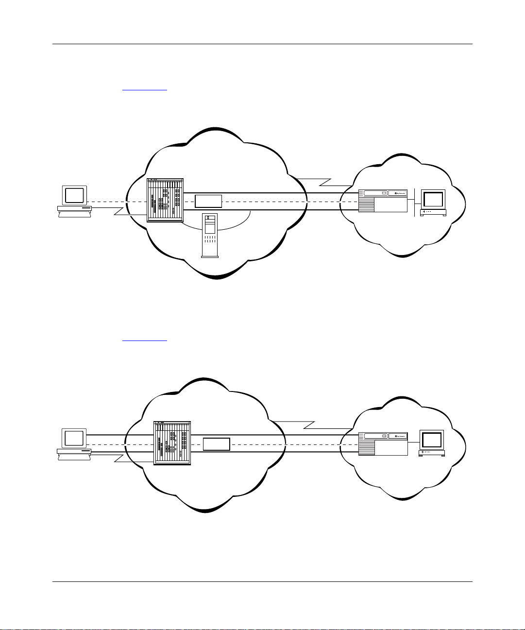
Example 1: Remote PC Calling the Corporate Network ................................................ B-1
Configuring the Remote Hosts ................................................................................ B-2
Configuring the LACs and the TMS ........................................................................ B-3
Configuring the LNS ................................................................................................ B-3
Data Path Through the Network .............................................................................. B-4
Example 2: Remote Router Calling the Corporate Network .......................................... B-5
Configuring the Dial-on-Demand Circuit ................................................................. B-6
Configuring the PPP Interface ................................................................................. B-6
Appendix C
Troubleshooting
Index
300016-B Rev. 00
vii
Page 8

Page 9

Figures
Figure 1-1. L2TP Network Using a LAC .....................................................................1-7
Figure 1-2. L2TP Network Using a RAS .....................................................................1-7
Figure 1-3. Packet Encapsulation Process .................................................................1-8
Figure 1-4. Tunnel Authentication Control Messages ...............................................1-13
Figure 1-5. Remote Router Dialing the LNS .............................................................1-16
Figure A-1. L2TP Configuration List Window ............................................................. A-2
Figure A-2. L2TP Tunnel Security List Window ......................................................... A-8
Figure A-3. L2TP IP Interface List Window .............................................................. A-10
Figure A-4. L2TP IP Interface Window .................................................................... A-10
Figure B-1. L2TP Network with PCs at the Remote Site ........................................... B-2
Figure B-2. L2TP Network with Routers at the Remote Site ..................................... B-5
300016-B Rev. 00
ix
Page 10

Page 11

Tables
Table C-1. Common L2TP Network Problems and Solutions ..................................C-1
300016-B Rev. 00
xi
Page 12

Page 13

About This Guide
If you are responsible for configuring L2TP, you need to read this guide.
If you want to Go to
Learn about L2TP and the Bay Networks implementation of L2TP. Chapter 1
Start L2TP on a router using default parameter settings. Chapter 2
Change default settings for L2TP parameters. Chapter 3
Obtain information about Site Manager parameters (this is the same
information you obtain using Site Manager online Help).
Review configuration examples. Appendix B
Troubleshoot L2TP configuration problems. Appendix C
Appendix A
Before You Begin
Before using this guide, you must complete the following procedures. For a new
router:
• Install the router (refer to the installation guide that came with your router).
• Connect the router to the network and create a configuration file (refer to
Quick-Starti ng Router s , Conf igur ing BaySt ac k Remote Acc ess , or Connecting
ASN Routers to a Network).
Make sure that you are running the latest version of Bay Networks
Site Manager software. For instructions, see Upgrading Routers from Version
7-11.xx to Version 12.00 and the BayRS Version 12.20 Document Change Notice.
300016-B Rev. 00
®
BayRS™ and
xiii
Page 14

Configuring L2TP Services
Conventions
bold text
Indicates text that you need to enter, command names,
and buttons in menu paths.
Example: Enter
Example: Use the
wfsm &
dinfo
command.
Example: ATM DXI > Interf ace s > PVCs identifies the
PVCs button in the window that appears when you
select the Interfaces option from the ATM DXI menu.
italic text Indicates variable values in command syntax
descriptions, new terms, file and directory names, and
book titles.
quotation marks (“ ”) Indicate the title of a chapter or section within a book.
screen text Indicates data that appears on the screen.
Example:
Set Bay Networks Trap Monitor Filters
separator ( > ) Separates menu and option names in instructions and
internal pin-to-pin wire connections.
Example: Protocols > AppleTalk identifies the
AppleTalk option in the Protocols menu.
Example: Pin 7 > 19 > 20
vertical line (
) Indicates that you enter only one of the parts of the
|
command. The vertical line separates choices. Do not
type the vertical line when entering the command.
Example: If the command syntax is
xiv
show at routes
show at routes
nets
, you enter either
|
show at nets
or
, but not both.
300016-B Rev. 00
Page 15

Acronyms
About This Guide
CHAP Challenge Handshake Authentication Protocol
IP Internet Protocol
ISDN Integrated Services Digital Network
ISP Interne t Service Provider
L2TP Layer 2 Tunneling Protocol
LAC L2TP access concentrator
LAN local area network
LCP Link Control Protocol
LNS L2TP network server
MPPP Multilink Point-to-Point Pro tocol
PAP Password Authenti cat ion Protocol
PPP Point-to-Point Protocol
RADIUS Remote Authentication Dial-In User Service
RAS remote access server
RIP Routing Information Protocol
SCCCN start control connection connected
SCCRP start control connection reply
SCCRQ start control connection request
TA terminal adapter
TCP/IP Transmission Control Protocol/Internet Protocol
TMS tunnel management server
UDP User Datagram Protocol
VPN virtual private network
WAN wide area network
300016-B Rev. 00
xv
Page 16

Configuring L2TP Services
Bay Networks Technical Publications
You can now print technical manuals and release notes free, directly from the
Internet. Go to support.baynetworks.com/library/tpubs. Find the Bay Networks
products for which you need documentation. The n locate the s pecific c ategory and
model or version for your hardware or software product. Using Adobe Acrobat
Reader, you can open the manuals and release notes, search for the sections you
need, and print them on most s tandard prin ters. You can download Acrobat Reader
free from the Adobe Systems Web site, www.adobe.com.
Documentation sets and CDs are a vailable through your local Bay Networ ks sales
office or account representative.
Bay Networks Customer Service
You can purchase a support contract from your Bay Networks distributor or
authorized reseller, or direct ly from Bay Networks Serv ices. For infor mation
about, or to purchase a Bay Networks service contract, either call your local Bay
Networks field sales office or one of the following numbers:
xvi
Region Telephone number Fax number
United States and
Canada
Europe 33-4-92-96-69-66 33-4-92-96-69-96
Asia/Pacific 61-2-9927-8888 61-2-9927-8899
Latin America 561-988-7661 561-988-7550
800-2LANW AN; th en enter Expr ess Routing
Code (ERC) 290, when prompted, to
purchase or renew a service contract
978-916-8880 (direct)
978-916-3514
Information about customer service is also available on the World Wide Web at
support.baynetworks.com.
300016-B Rev. 00
Page 17

How to Get Help
If you purchased a service contract for your Bay Networks product from a
distributor or authorized reseller, contact the technical support staff for that
distributor or reseller for assistance.
If you purchased a Bay Networks service program, call one of the following Bay
Networks Technical Solutions Centers:
Technical Solutions Center Telephone number Fax number
Billerica, MA 800-2LANWAN 978-916-3514
Santa Clara, CA 800-2LANWAN 408-495-1188
Valbonne, France 33-4-92-96-69-68 33-4-92-96-69-98
Sydney, Australia 61-2-9927-8800 61-2-9927-8811
Tokyo, Japan 81-3-5402-0180 81-3-5402-0173
Bay Networks Educational Services
About This Guide
300016-B Rev. 00
Through Bay Networks Educa tional Services , you can attend cl asses and purcha se
CDs, videos, and computer-based training programs about Bay Networks
products. Training programs can take place at your site or at a Bay Networks
location. For more information about training programs, call one of the following
numbers:
Region Telephone number
United States and Canada 800-2LANWAN; then enter Express Routing Code (ERC)
282 when prompted
978-916-3460 (direct)
Europe, Middle East, and
Africa
Asia/Pacific 61-2-9927-8822
Tokyo and Japan 81-3-5402-7041
33-4-92-96-15-83
xvii
Page 18

Page 19

Chapter 1
L2TP Overview
The Layer 2 Tunneling Protocol (L2TP) provides remote users, such as
telecommuters, mobile professionals, and personnel in remote branch offices,
with dial-in access to a corporate network. L2TP enables users to create a virtual
private network (VPN), which uses the existing physical infrastructu re of a public
network, such as the Internet, but offers the security and exclusivity of a private
network.
This chapter contains the following information:
300016-B Rev. 00
Topic Page
L2TP Benefits 1-2
What Is Tunneling? 1-2
Components of an L2TP Networ k 1-4
L2TP Packet Encapsulation 1-8
Making a Connection Across an L2TP Network 1-9
Security in an L2TP Networ k 1-10
Bay Networks L2TP Implementation 1-11
Where to Go Next 1-17
1-1
Page 20

Configuring L2TP Services
L2TP Benefits
L2TP has several advantages:
• Users and businesses can take advantage of existing network equipment and
resources.
Corporations do not need to maintain and manage remote access servers and
other special networking equipment for remote users. Instead, they can use
their exis ting Inter net l eas ed conn ectio ns and res ource s at t he In ter net Se rvice
Provider (ISP) network, thereby significantly reducing corporate networking
and maintenance costs.
In addition, corporations do not need to provide technical support to the
remote users. Because the remote user is making a local call to the ISP, the
ISP provides technical assistance if the user has trouble making connections.
• Remote users can place a free local call to their ISP for access to the Internet,
eliminating long-distance toll calls required to dial the corporate network
directly.
• ISPs earn more business from corporate customers using the equipment,
thereby increasing the ISP’s revenues.
• L2TP is a standards-base d protocol that provides great er interoperability with
networking equipment from other vendors.
What Is Tunneling?
Tunn eling i s a w ay of fo rw ardi ng traffic from remote users to a c orpora te n etwo rk
through an IP network. A tunnel is a virtual connection between two sites, for
example, an access concentrator at the ISP networ k and a router at the corporate
network. Tunneling across an existing public network such as the Internet creates
a virtual private network that offers corporate network access to a wider range of
remote users.
L2TP is a tunneling mechanism that extends the end point of the Point-to-Point
Protocol (PPP) connection from an L2TP access concentrator (LAC) or remote
access server (RAS) at the ISP network to an L2TP network server (LNS) at the
corporate site.
1-2
300016-B Rev. 00
Page 21

Multiple users can communicate through a single tunnel between the same LAC
and LNS pair. Each user transmits and receives data in an individual L2TP
session.
The LAC brings down the tunnel for any one of the following reasons:
• A network failure occurs.
• The LAC or other equi pment at the ISP is not operating properly. If the LAC
• There are no active sessions inside the tunnel.
• The system administrator at the ISP terminates the user connection.
• The LAC is not responding to a Hello packet from the LNS.
For the LAC to reestablish a tunnel, the remote user has to place a n ew call .
L2TP Sessions
L2TP Overview
fails, all tunnel users are disconnected.
An individual session ends when a remote user disconnects the call, but
multiple sessions can run inside a single tunnel.
300016-B Rev. 00
Packets are exchanged across an L2TP tunnel during an L2TP session. An L2TP
session is create d when an e nd-to-end WAN connection is established between the
remote host and the LNS.
The L2TP portion of the packets sent through the tunnel contains a header with a
call ID field (also called a session ID) and a tunnel ID field. The call ID field,
which indicates the session that th e WAN packet belongs to, is negot iated bet ween
the LAC and the LNS when the L2TP call is set up. The tunnel ID specifies the
tunnel that the L2TP session is using.
In addition to the fields in the header, the L2TP packet contains a call serial
number, which is a unique number for each L2TP call. This number matches the
call to the L2TP session.
For an L2TP session, you can enable flow control. Flow control manages
congestion across t he connection, en sures that p ackets are not lost, and make s sure
the devices at each end of the connection are communicating properly.
To enable flow control, see Chapter 3, “Customizing L2TP Services.”
1-3
Page 22

Configuring L2TP Services
Components of an L2 TP Network
The following sections describe the components of an L2TP network. For
illustrations of L2TP networks, see Figures 1-1
Remote Host
At the remote site is the user who wants to dial in to the corporate network. The
remote user can be located anywhere, provided that the user can dial into an ISP
network using a PC or a router. The ISP provides the connection to the Internet.
The host at the remote site can be a PC or router th at uses PPP f or dial-up
connections.
• If the PC or router does not have built-in L2TP software capabilities, it dials
into a LAC, which provides a tunnel across the Internet to the corporate LNS.
• If the PC or router is an L2TP client, that is, it has built-in L2TP functionality,
the L2TP client software provides a tunnel through a RAS across the Internet
to the corporate LNS. A LAC is unnecessary with an L2TP client.
The main difference between connecting an L2TP client and a nonclient is the
starting point of the tunnel. For an L2TP client, the tunnel begins at the PC or
router; for a non-L2TP client , the tunnel begins at the LAC. Al l tu nnel s en d at the
LNS.
and 1-2 on page 1-7.
1-4
Note:
This guide’s primary focus is on an L2TP network between a remote
host that does not ha ve b uilt-in L2TP capabi lities a nd uses a LA C, rather than a
RAS.
300016-B Rev. 00
Page 23

L2TP Access Concentrator (LAC)
The L2TP access concentrator (LAC) resides at the ISP network. The LAC
establishes the L2TP tunnel between itself and the LNS.
Note:
In this guide, the term LAC refers to a remote access se rver w ith L2TP
capabilities. The term RAS refers to a remote access server without L2TP
capabilities.
When the remote user places a call to the ISP network, this call goes to the LAC.
The LAC then negotiates the activation of an L2TP tunnel with the LNS. This
tunnel carries data from the remote user to the corporate network.
For more inform ation about the Bay Networks implementation of the LAC in an
L2TP network, see “Bay Networks L2TP Implementation
Remote Access Server (RAS)
The remote access server (RAS) resides at the ISP network. If the remote host is
an L2TP client, the tunnel is established from the remote client through a RAS to
an LNS at the corporate network. In this situation, there is no need for a LAC.
L2TP Overview
” on page 1-11.
The RAS does not establish the tunnel; it only forwards already tunneled data to
the destination.
Tunnel Management Server (TMS)
At the ISP network, there needs to be a mechanism for id ent if yin g L2TP tunneled
users so that the LAC can construct the L2TP tunnel. Bay Networks uses a
mechanism called a tunnel management server (TMS); other vendors may use a
different method.
300016-B Rev. 00
1-5
Page 24

Configuring L2TP Services
L2TP Network Server (LNS)
The L2TP network server (LNS) is a router that resides at the corporate network
and serves as the termination point for L2TP tunnels and sessions.
The LNS authenticates the PPP connect ion reques t and allo ws the end- to-end PPP
tunneled connection. The LNS may also perform user authentication with a
RADIUS server to prevent unauthorized users from accessing the network;
however, user authentication may also be done by the LNS itself.
An LNS can support multip le remote users , each communi catin g withi n the ir own
L2TP session. The L2TP session is the virtual end-to-end connection over which
the LAC sends data to the LNS.
The Bay Networks router is an LNS. For information about the Bay Networks
LNS, see “Bay Networks L2T P Implementa tion
RADIUS Server
An L2TP network may include a Remote Authentication Dial-in User Service
(RADIUS) server. The RADIUS server has three main functions in an L2TP
network:
” on page 1-11.
1-6
• Authenticating the remote users
• Assigning IP addresses to the remote users
• Providing accounting services for corporate billing
The RADIUS server database centralizes the authentication function, eliminating
the need to confi gure e ach LNS with use r names a nd passw or ds. It also as signs an
IP address to a remote host to identify the host. Finally, the RADIUS server can
provide accou n ti ng s ervices for the corporate network, ca lculating billing charges
for an L2TP session.
For information about the Bay Networks implementation of RADIUS user
authentication and accounting, see “RADIUS User Authentication
and “RADIUS Accounting
” on page 1-15.
” on page 1-14
300016-B Rev. 00
Page 25
Examples of L2TP Networks
Figure 1-1 shows an L2TP network that uses a LAC to connect to the LNS. The
tunnel is between the LAC and the LNS.
ISP network
L2TP Overview
Remote
host
PC
No L2TP
functionality
PPP
connection
LAC
T unnel
Data
TMS
Figure 1-1. L2TP Network Using a LAC
Figure 1-2 shows an L2TP network that uses a RAS to connect to the LNS. The
tunnel is between the PC (the L2TP client) and the LNS.
ISP network
Remote
host
PC
Tunnel
RAS
Data
Frame rela y
connection
Frame relay
connection
Corporate network
LNS
RADIUS
server
L2T0003A
Corporate network
LNS
L2TP
client
Figure 1-2. L2TP Network Using a RAS
300016-B Rev. 00
RADIUS
server
L2T0004A
1-7
Page 26

Configuring L2TP Services
L2TP Packet Encapsulation
The PC or router at the remote site sends PPP packets to the LAC. The LAC
encapsulates these incoming packets in an L2TP packet and sends it across an IP
network through a bidirectional tunnel. After the LNS receives the packets, it
decapsulates them and terminates the PPP connection.
Figure 1-3
network.
Layer 2
protocol
shows how data is encapsulated for transmission over an L2TP
Remote user places a call
LAC
LNS
DATA
PPP
IPL2TP
DATA
PPP IP
IP/UDP
1-8
IP DATA
Data packet moves to the corporate network
L2T0005A
Figure 1-3. Packet Encapsulation Process
300016-B Rev. 00
Page 27

Making a Connection Across an L2TP Network
The following steps explain how a remote user connects across an L2TP network
that includes a Bay Networks LAC, TMS, and LNS (see Figure 1-1
1.
The remote user dials a LAC at the local ISP network to establish a PPP
connection to the corporate network.
In the call, the user incl udes any required information, for example, a user
name, including a domain name, and a password. When the user dials in, he
enters a name, for example, jdoe@baynetworks.com; jdoe is the user name
and baynetworks.com is the domain name.
2.
The LAC receives the call and passes the domain name to the TMS.
If the TMS finds a match for the domain name, a tunnel can be created. The
TMS also checks the number of current connections so that they will not
exceed the maximum number allowed.
If the user is not a tunnel candidate, as determined by the domain name, the
LAC assumes that the remote host is making a regular dial-in request and
authenticates the user accordingly.
L2TP Overview
on page 1-7).
300016-B Rev. 00
3.
The LAC tries to establish an L2TP tunnel with the LNS.
For the LAC to send a tunnel request to the LNS, it needs the address of the
LNS. The LAC requests the address from the TMS. It then checks for this
address in its own routing table. After obtaining the address, the LAC sends a
tunnel request to the LNS. The LNS may perform tunnel authentication, if
configured to do so. If the LAC and LNS complete tunnel authentication
successfully, the LAC establishes the tunnel.
4.
After the tun nel is establis hed, the LAC forwards the remote user’s name to
the LNS, which verifies the user’s identity with the corporate RADIUS server.
If the RADIUS server recognizes the user name, it replies with an
acknowledgment and an IP address that it assigns to the remote user for the
duration of the call. This IP address identifies the remote user who may not
have an address of his own.
5.
After the remote user i s succ essfu ll y auth entic ate d, the user h as an e nd- to-en d
PPP connection to the corporate network over the Internet.
The tunnel can now carry a user session during which the LAC and the LNS
exchange PPP packets.
1-9
Page 28

Configuring L2TP Services
Security in an L2TP Network
You can configure two layers of security in an L2TP network:
• Tunnel authent i cat ion
Tunnel authentication is the process of negotiating the establishment of a
tunnel between the LAC and the LNS.
• User authentication
The network administrator at the corporate site can configure a RADIUS
server with th e names and passwords of authorized users. The server’s
database centralizes the authentication function, eliminating the need to
configure each LNS with user names and passwords.
When the LNS receives a call, it forwards the user information to the
RADIUS server, which verifies whet her the user is authorized to access the
network.
You can also configure the LNS to perform user authentication if a RADIUS
server is not part of the network configuration.
For more information about the Bay Networks implementation of tunnel and user
authentication, see “Tunnel Authenticati on
Authentication” on page 1-14.
” on page 1-12 and “RADIUS User
1-10
300016-B Rev. 00
Page 29

Bay Networks L2TP Implementation
In an L2TP network, the Bay Netw or ks rout er is th e LNS. LNS software operates
®
on the BLN
The Bay Networks LNS has the following characteristics:
• Each slot can act as an LNS, which means that one rou ter can ha v e many LNS
interfaces, eac h with its o wn address . You can have as many LNS inte rface s as
there are available slots on the router.
• The LNS performs user authentication with a RADIUS server to prevent
unauthorized users from accessing the network.
• The LNS accepts only incoming calls; it does not place calls to the LAC.
• The Bay Networks L2TP implementation supports only IP traffic through the
L2TP tunnel. The LNS supports only numbered IP addresses.
• The router interface between the ISP and the corporate network (see
Figure 1-1
(including PPP multilink), or ATM. Bay Networks recommends that you use a
high-speed link, such as T1, for the leased connection.
, BCN®, and ASN™ platforms.
on page 1-7) is a leased line operating with frame relay, PPP
L2TP Overview
300016-B Rev. 00
• The LNS terminates PPP multilink and PPP encapsulated data within an
L2TP packet.
• The LNS operates with the LAC implementation configured on the Bay
Networks Model 5399 Remote Access Concentrator.
• The host (PC or router) dialing into the ISP network can be on the same
subnet as the IP interface on the LNS.
• The LNS supports RIP. RIP is particularly useful when the remote host is a
router, because it enables the LNS to learn routing information from the
remote router.
For instructions on how to configure a Bay Networks router as an LNS, see
Chapter 2, “Starting L2TP.”
1-11
Page 30

Configuring L2TP Services
Tunnel Management
The Bay Networks tunnel management server (TMS), which resides at the ISP
network, stores the TMS database. This database contains the remote users’
domain name, the IP address information of each LNS, and other tunnel
addressing information that the network administrator configures. The LAC
requests this information from the TMS to construct the L2TP tunnel.
When the LAC receives a call, it forwards the domain name to the TMS. The
domain name is the porti on of the user’s address that specif ies a parti cular locat ion
in the network. For example, if the user name is jdoe@baynetworks.com,
baynetworks.com is the domain name. The TMS looks up the domain name and
verifies that the remote user is an L2TP user. The TMS also provides the LAC
with the addressing information required to establish a tunnel to the correct LNS.
Note:
The domain name referred to in this guide is a domain identifier that
does not follo w a specif ic f ormat. It is not r elated to an y Domain Name Sy stem
(DNS) protocol requirements.
Tunnel Authentication
1-12
For security purposes, you can enable the LNS to perform tunnel authentication.
Tunnel authentication is the process of negotiating the establishment of a tunnel.
During tunnel authentication, the LNS identifies the L2TP c lient or LAC by
comparing the LAC’s tunnel authentication password with its own password. If
the passwords match, the LNS permits the LAC to establish a tunnel.
The LAC does not send the tunnel authentication password as a plain-text
message. The exchange of passwords works much like the PPP Challenge
Handshake Authenti cation Protoc ol (CHAP). When one si de recei v es a chal lenge,
it responds with a value that is calculated based on the authentication password.
The receiving side matches the value against its own calculation. If the values
match, authentication is successful.
Tunnel authentication occurs in both directions, which means that the LAC and
LNS both try to verify the other’s identity.
300016-B Rev. 00
Page 31

L2TP Overview
You can enable tunnel authentication on the Bay Networks LNS. If tunnel
authentication is d isa bl ed, whi ch i s t he default, the LNS sends a default chall en ge
response to the LAC during the authentication process so that the tunnel can be
established. The LNS cannot send outgoing calls, so it cannot initiate tunnel
authentication.
During tunnel authentication, the following exchange of messages takes place:
1.
The LAC sends a tunnel setup message, called the start control connection
request (SCCRQ) mess a ge to the LNS. This message includes a challenge to
the LNS.
2.
The LNS replies with a tunnel response, a challenge response, and its own
challenge message. This is called the start control connection reply (SCCRP)
message.
3.
The LAC replies with a challenge response that includes its tunnel
authentication password. This is the start control connection connected
(SCCCN) message.
4.
If this same password is configured for the LNS, the LNS grants approval to
the LAC to establish a tunnel.
300016-B Rev. 00
Figure 1-4
shows tunnel authentication.
ISP network
PPP connection
LAC
SCCRQ
tunnel request and challenge
tunnel response, challenge response,
and LNS challenge
SCCCN
challenge response
Figure 1-4. Tunnel Authentication Control Messages
Corporate network
LNS
SCCRP
L2T0006A
1-13
Page 32

Configuring L2TP Services
After tunnel authentication is complete, it does not need to be repeated for other
calls to the same LAC.
RADIUS User Authentication
RADIUS user authenticat ion is ena bled b y def ault on t he Bay Netw orks LNS; yo u
must configure this feature so that the LNS can validate the remote user’s identity
before allowing access to the network.
The network administrator at the corporate site must configure a RADIUS server
with the names and passwords of authorized users. When the LNS recei ves a call,
it forwards an authentication request with the user information to the RADIUS
server, which verifies whether the user is authorized. If the user is permitted
access to the network, the RADIUS server replies with an acknowledgment
message and the appropriate IP address for that user to make a connection.
The IP address that the RADIUS server assigns is essential because many remote
hosts may not have their own addresses. The LNS uses the address to identify the
remote host and send data to the remote user. After the session ends, the IP
address becomes available for another user.
1-14
If the corporate network uses an existing RADIUS database for L2TP
connections, you do not have to reconfigure the names in the database. The LNS
automaticall y remo v es the d omain p ortio n of the user n ame tha t is i ncluded as par t
of the call from the LAC to the LNS. If you want to keep the domain name, you
can disable this feature. For instructions, see Chapter 3, “Customizing L2TP
Services.”
For more inform ation about configuring Bay Networks routers as RADIUS
servers, see Configuring RADIUS.
300016-B Rev. 00
Page 33

RADIUS Accounting
The RADIUS server can provide accounting services in addition to its
authentication services. RADIUS accounting is enabled by default on the Bay
Networks LNS.
The RADIUS accounting server calculates billing charges for an L2TP session
between the remote user and the LNS. To determine thes e char g es, the s erv e r uses
information that it receives from the LNS, such as the status of each call and the
number of packets sent during the session. Using this data, the server determines
billing char ges, whi ch the netw or k admin istr ator can use to man age net w ork co sts.
The primary RADIUS accounting server can be the same server as the
authentication server or it can be a different server.
For more information about RADIUS accounting, see Configuring RADIUS.
L2TP IP Interface Addresses
When configuring the Bay Networks LNS, you must configure an IP address for
every slot that has an L2TP interface. This address is referred to as the L2TP IP
interface address. The L2TP IP interface can be any valid IP address.
L2TP Overview
300016-B Rev. 00
The L2TP IP interface address is internal to the LNS. When communicating with
the remote user , the LNS associates the user’s IP address, which is assigned b y the
RADIUS server, with the L2TP IP interface address that you configured.
The L2TP IP interface address and the RADIUS-assigned IP address do not have
to be in the same subnet.
1-15
Page 34

Configuring L2TP Services
PC 1
PC 2
LAC
192.168.18.41
192.32.25.34
192.32.25.35
Dial-in router
LNS
192.168.19.34
L2TP IP, RIP enabled
192.32.33.94
LAN interface
RIP enabled
192.32.25.33
Dial-on-demand
RIP enabled
Dial-optimized
routing enabled
192.32.25.66
L2T0009B
Remote Router Configuration
If the host at the remote site is a Bay Networks router, you may need to configure
a dial-on-dema nd circu it for the rem ote rout er’s dial-up interf ace to the LAC at the
ISP network.
Enable RIP on both the dial-on-demand circuit and the attached LAN interface of
the remote router, so that the LNS can learn routin g information from the remote
router . To av oid unneces sarily acti v ating the circuit bec ause of RIP pack ets, enabl e
dial-optimized routing for the dial-on-demand circuit (see Figure 1-5
In addition, conf igu re a def ault or stati c route f or the remote ro uter , which us es the
next-hop address that corresponds to the L2TP IP interface address of the LNS.
This default or static route enables the remote router to deliver L2TP packets to
the LNS.
).
1-16
Figure 1-5. Remote Router Dialing the LNS
300016-B Rev. 00
Page 35

Where to Go Next
Go to one of the following chapters for more information:
If you want to Go to
Start L2TP on a router using default parameter settings. Chapter 2
Change default settings for L2TP parameters. Chapter 3
Obtain information about Site Manager parameters (this is the same
information you obtain using Site Manager online Help).
Review configuration examples. Appendix B
Troubleshoot L2TP configuration problems. Appendix C
L2TP Overview
Appendix A
300016-B Rev. 00
1-17
Page 36

Page 37

Chapter 2
Starting L2TP
The quickest way to start L2TP is to ena ble it with the default configuration that
Bay Networks software supplies. This configuration uses all available parameter
defaults. You need to supply values for several parameters that do not ha v e de fa ult
values.
This chapter includes the following information:
Topic Page
300016-B Rev. 00
Planning Considerations for an L2TP Net work 2-2
Preparing a Configuration File 2-3
Enabling L2TP on an Unconfigured WAN Interface 2-4
Enabling L2TP on an Existing PPP Interface 2-5
Enabling L2TP on an Existing Frame Relay Interface 2-7
Enabling L2TP on an Existing ATM Interface 2-9
2-1
Page 38

Configuring L2TP Services
Planning Considerations for an L2TP Network
This guide primarily explains how to configure a Bay Networks BLN, BCN, or
ASN router as an LNS in an L2TP network. To successfully operate in an L2TP
network, obtain the following information to configure the LNS.
Tunnel Authentication Passwords
If you plan to enable tunnel authentication, which is optional for the Bay
Networks LNS, you must obtain the LAC password from your ISP. For more
information about the authentication process, see “Tunnel Authentication” on
page 1-12.
RADIUS Server Information
The Bay Networks implementation of L2TP requires that you configure a
RADIUS server to perform user authentication and to assign IP addresses to
remote users.
For the RADIUS server, do the following:
2-2
• Configure the RADIUS server with user names and domain names.
• Obtain the address and password of the RADIUS server to enter in the LNS
configuration.
• Configure the RADIUS server to assign IP addresses to remote users.
This address identifies the remote user to the LNS during an L2TP session. If
the remote user does not have a preconfigured address, the onl y way to assign
addresses is by the RADIUS server. This address is also used for network
communication across the subscriber network.
For more inform ation about configuring Bay Networks routers as RADIUS
servers, see Configuring RADIUS.
300016-B Rev. 00
Page 39

Preparing a Configura tion File
Before starting L2TP, you must create and save a configuration file with at least
one WAN interface, for example, a synchronous or MCT1 port.
For information about the Site Manager configuration tool and how to work with
configuration files, see Configuring and Managing Routers with Site Manager.
To open the configuration file, complete the following tasks:
Site Manager Procedure
You do this System responds
Starting L2TP
1. In the main Site Manager window, choose
.
Tools
2. Choose
3. Choose
Dynamic
4. Select the file and click on OK. The Configuration Manager window
Configuration Manager
Local File, Remote File
.
. The Configuration Manager window
, or
The Tools menu opens.
opens.
Site Manager prompts you for the
configuration file you want to open.
opens, displaying the router modules.
From the Configuration Manager window, go to one of the following sections to
enable L2TP:
Section Page
Enabling L2TP on an Unconfigured WAN Interface
Enabling L2TP on an Existing PPP Interface 2-5
Enabling L2TP on an Existing Frame Relay Interface 2-7
Enabling L2TP on an Existing ATM Interface 2-9
2-4
300016-B Rev. 00
2-3
Page 40

Configuring L2TP Services
Enabling L2TP on an Unconfigured WAN Interface
To enable L2TP on an unconfigured WAN interface, complete the followi ng tasks :
Site Manager Procedure
You do this System responds
1. In the Configuration Manager window,
choose a WAN connector.
2. Accept the default circuit name or change
it, then click on OK.
3. Choose
click on OK.
4. Choose
5. Enter the IP address of the LNS (router),
then click on OK.
6. Set the following parameters:
• RADIUS Primary Server IP Address
• RADIUS Primary Server Password
•
7. Click on OK. The L2TP Tunneling Security w indow
8. Click on OK. The L2TP IP Interf ace List w indow ope ns,
9. Set the following parameters:
• L2TP IP Interface Address
•
PPP, Frame Relay
, then click on OK. The IP Configuration window opens.
L2TP
RADIUS Client IP Address
Click on
descriptions beginning on page A-5.
Subnet Mask
or see the param eter
Help
, or
ATM
then
The Add Circuit window opens.
The WAN Protocols window opens.
The Select Protocols window opens.
The L2TP Configuration window opens.
opens.
followed by the L2TP IP Configuration
window.
Site Manager displays a message
alerting you of the time delay to create
the L2TP tunnel circuits.
2-4
Click on
descriptions beginning on page A-11.
10. Click on OK. You return to the L2TP IP Interface List
or see the param eter
Help
window, which displays the IP interface
address and the subnet mask. A
message windo w opens that r eads,
Configuration is completed
L2TP
.
(continued)
300016-B Rev. 00
Page 41

Starting L2TP
Site Manager Procedure
You do this System responds
11. Click on OK.
12. Click on
. You return to the Configuration Manager
Done
(continued)
window.
Enabling L2TP on an Existing PPP Interface
To enable L2TP on an interface with PPP and IP already enabled, complete the
following tasks:
Site Manager Procedure
You do this System responds
1. In the Configuration Manager window,
choose a WAN connector.
2. Choose
3. Choose
the window.
4. Choose
5. Choose
6. Set the following parameters:
• RADIUS Primary Server IP Address
• RADIUS Primary Server Password
•
Edit Circuit
Protocols
Add/Delete
L2TP
RADIUS Client IP Address
. The Circuit Definition window opens.
in the top left corner of
. The Select Protocols window opens.
, then click on OK. The L2TP Configuration window opens.
The Edit Connector window opens.
The Protocols menu opens.
300016-B Rev. 00
Click on
descriptions beginning on page A-5.
7. Click on OK. The L2TP Tunneling Security w indow
8. Click on OK. The L2TP IP Interf ace List w indow ope ns,
or see the parameter
Help
opens.
followed by the L2TP IP Configuration
window.
(continued)
2-5
Page 42

Configuring L2TP Services
Site Manager Procedure
(continued)
You do this System responds
9. Set the following parameters:
• L2TP IP Interface Address
• Subnet Mask
Click on
or see the parameter
Help
Site Manager displays a message
alerting you of the time delay to create
the L2TP tunnel circuits.
descriptions beginning on page A-11.
10. Click on OK. You return to the L2TP IP Interface List
window, which displays the IP interface
address and the subnet mask. A
message windo w opens that r eads,
Configuration is completed
L2TP
.
11. Click on OK.
12. Click on
. You return to the Circuit Definition
Done
window.
13.Choose
14.Choose
. The File menu opens.
File
. You return to the Configuration Manager
Exit
window.
2-6
300016-B Rev. 00
Page 43

Enabling L2TP on an Existing Fra m e Relay Interface
T o enable L2 TP on an interfa ce with f rame rela y and IP al ready ena bled, compl ete
the following tasks:
Site Manager Procedure
You do this System responds
Starting L2TP
1. In the Configuration Manager window,
choose a WAN connector.
2. Choose
3. Choose
4. Choose
the window.
5. Choose
6. Choose
7. Set the following parameters:
• RADIUS Primary Server IP Address
• RADIUS Primary Server Password
•
8. Click on OK. The L2TP Tunneling Security w indow
9. Click on OK. The L2TP IP Interf ace List w indow ope ns,
10. Set the following parameters:
• L2TP IP Interface Address
• Subnet Mask
Edit Circuit
Services
Protocols
Add/Delete
L2TP
RADIUS Client IP Address
Click on
descriptions beginning on page A-5.
Help
. The Frame Relay Circuit D efinition
. The Frame Relay Servic e List window
in the top left corner of
. The Select Protocols window opens.
, then click on OK. The L2TP Configuration window opens.
or see the parameter
The Edit Connector window opens.
window opens.
opens.
The Protocols menu opens.
opens.
followed by the L2TP IP Configuration
window.
Site Manager displays a message
alerting you of the time delay to create
the L2TP tunnel circuits.
300016-B Rev. 00
Click on
descriptions beginning on page A-11.
or see the param eter
Help
(continued)
2-7
Page 44

Configuring L2TP Services
Site Manager Procedure
(continued)
You do this System responds
11. Click on OK. You return to the L2TP IP Interface List
window, which displays the IP interface
address and the subnet mask. A
message windo w opens that r eads,
Configuration is completed
L2TP
.
12. Click on OK.
13. Click on
. You return to the Frame Relay Service
Done
List window.
14. Click on
. You return to the Frame Relay Circuit
Done
Definition window.
15. Click on
. You return to the Configuration Manager
Done
window.
2-8
300016-B Rev. 00
Page 45

Enabling L2TP on an Existing ATM Interface
To enable L2TP on an interf ace with ATM and IP already enabled, you ca n enab le
L2TP in two ways. If your interface uses a COM connector, complete the tasks in
the following table. If your interface uses an AT M connector, go to page 2-10
Site Manager Procedure
You do this System responds
Starting L2TP
.
1. In the Configuration Manager window,
choose a WAN connector.
2. Choose
3. Choose
4. Choose
5. Choose
6. Set the following parameters:
• RADIUS Primary Server IP Address
• RADIUS Primary Server Password
•
7. Click on OK. The L2TP Tunneling Security w indow
8. Click on OK. The L2TP IP Interf ace List w indow ope ns,
9. Set the following parameters:
• L2TP IP Interface Address
• Subnet Mask
10. Click on OK. You return to the L2TP IP Interface List
11. Click on OK.
Edit Circuit
Group Protocol s
Add/Delete
L2TP
RADIUS Client IP Address
Click on
descriptions beginning on page A-5.
Click on
descriptions beginning on page A-11.
Help
Help
. The Circuit Definition window opens.
. The Group Protocols menu opens.
. The Select Protocols window opens.
, then click on OK. The L2TP Configuration window opens.
or see the parameter
or see the param eter
The Edit Connector window opens.
opens.
followed by the L2TP IP Configuration
window.
Site Manager displays a message
alerting you of the time delay to create
the L2TP tunnel circuits.
window, which displays the IP interface
address and the subnet mask. A
message windo w opens that r eads,
Configuration is completed
L2TP
.
(continued)
300016-B Rev. 00
2-9
Page 46

Configuring L2TP Services
Site Manager Procedure
You do this System responds
12. Click on
13.Choose
14.Choose
. You return to the Circuit Definition
Done
. The File menu opens.
File
. You return to the Configuration Manager
Exit
(continued)
window.
window.
If your ATM in terface uses an AT M connector, complete the following tasks:
Site Manager Procedure
You do this System responds
1. In the Configuration Manager window,
choose an ATM connector.
2. Choose
3. Choose
4. Choose
5. Choose
6. Complet e steps 6 through 11 in the
previous table.
7. Click on
8. Click on
9. Click on
Service Attributes
Protocols
Add/Delete.
L2TP
Done
Done
Done
. The Protocols menu opens.
, then click on OK. The L2TP Configuration window opens.
. You return to the ATM Service Records
. You return to the Edit ATM Connector
. You return to the Configuration Manager
. The ATM Service Records List window
The Edit ATM Connector window opens.
opens.
The Select Protocols window opens.
Site Manager enables L2TP.
List window.
window.
window.
2-10
300016-B Rev. 00
Page 47

Chapter 3
Customizing L2TP Services
When you enable L2TP, default values are in effect for most parameters (see
parameter descriptions in Appendix A, “L2TP Parameters”). You may want to
change some of these values, depending on the requirements of your network.
This chapter includes the following information:
Topic Page
Modifying the L2TP Protocol Configuration 3-2
Modifying RADIUS Server Information 3-3
Changing th e LNS System Name 3-4
Modifying the Number of L2TP Sessio ns Permitted 3-5
Keeping the Remote User’s Domain Name 3-6
Changing th e Domain Name Delimiter 3-7
Enabling Tunnel Authentication 3-8
Modifying L2TP IP Interface Addresses 3-9
Disabling RIP 3-10
Disabling L2TP 3-10
Deleting L2TP from a PPP Interface 3-11
Deleting L2TP from a Frame Relay Interface 3-12
Deleting L2TP from an ATM Interface 3-13
300016-B Rev. 00
3-1
Page 48

Configuring L2TP Services
Modifying the L2TP Protocol Configuration
To modify how data is transmitted across an L2TP network, such as the number,
frequency, and timing of data and acknowledgment packets exchanged between
the LNS and LAC, you can modify the L2TP protocol parameters.
To modify the L2TP protocol configuration, complete the following tasks:
Site Manager Procedure
You do this System responds
1. In the Configuration Manager window,
choose
2. Choose
3. Choose
4. Choose
5. Select an LNS entry from the list.
6. Edit any of the following parameters:
• Receive Window Size
• Retransmit Timer (seconds)
• Maximum Retransmit
• Hello Timer (seconds)
• Ack Timeout (milliseconds)
•
7. Click on
Protocols
. The IP menu opens.
IP
L2TP
L2TP Configuration
Tunnel Flow Control
Click on
descriptions beginning on page A-3.
Done
.
. The L2TP menu opens.
. The L2TP Configuration List window
or see the param eter
Help
. You return to the Configuration Manager
The Protocols menu opens.
opens.
window.
3-2
300016-B Rev. 00
Page 49

Modifying RADIUS Server Information
If you change the address of the RADIUS ser ver that you are using to aut hentica te
remote users and manage accounting functions, you must update the server
address information on the LNS.
For more information about using a RADIU S server in an L2TP network, see
“RADIUS Server” on page 1-6.
To modify the address of the RADIUS server, complete the following tasks:
Site Manager Procedure
You do this System responds
Customizing L2TP Servic es
1. In the Configuration Manager window,
choose
2. Choose
3. Choose
4. Choose
5. Select an LNS entry from the list.
6. Set the following parameters:
• RADIUS Primary Server IP Address
• RADIUS Primary Server Password
•
7. Click on
Protocols
. The IP menu opens.
IP
L2TP
L2TP Configuration
RADIUS Client IP Address
Click on
descriptions beginning on page A-5.
Done
.
. The L2TP menu opens.
. The L2TP Configuration List window
or see the param eter
Help
. You return to the Configuration Manager
The Protocols menu opens.
opens.
window.
You can also modify the RADIUS information in the configuration windows
specific to RADIUS. For more information, see Configuring RADIUS.
300016-B Rev. 00
3-3
Page 50

Configuring L2TP Services
Changing the LNS System Name
The LNS system name is the name of the router. This name is used during tunnel
setup to identify the LNS uniquely.
By default, Site Manager en ters the syste m name that you initially configured
when first accessing the router. See Configuring and Managing Routers with Site
Manager for more details about system information.
To change the LNS system name, complete the following tasks:
Site Manager Procedure
You do this System responds
1. In the Configuration Manager window,
choose
2. Choose
3. Choose
4. Choose
5. Select an LNS entry from the list.
6. Set the
Click on
description on page A-5.
7. Click on
Protocols
. The IP menu opens.
IP
L2TP
L2TP Configuration
LNS System Name
Help
Done
.
. The L2TP menu opens.
. The L2TP Configuration List window
parameter.
or see the param eter
. You return to the Configuration Manager
The Protocols menu opens.
opens.
window.
3-4
300016-B Rev. 00
Page 51

Customizing L2TP Servic es
Modifying the Number of L2TP Sessions Permitted
You can modify the maximum number of active L2TP sessions that the LNS can
manage. The default is 100 sessions.
For more information about L2TP sessions, see “L2TP Sessions” on page 1-3.
To change the maximum number of L2TP sessions supported by the LNS,
complete the following tasks:
Site Manager Procedure
You do this System responds
1. In the Configuration Manager window,
choose
2. Choose
3. Choose
4. Choose
5. Select an LNS entry from the list.
6. Set the
Click on
description on page A-3.
7. Click on
Protocols
. The IP menu opens.
IP
L2TP
L2TP Configuration
Max L2TP Sessions
Help
Done
.
. The L2TP menu opens.
. The L2TP Configuration List window
parameter.
or see the param eter
. You return to the Configuration Manager
The Protocols menu opens.
opens.
window.
300016-B Rev. 00
3-5
Page 52

Configuring L2TP Services
Keeping the Remote User’s Domain Name
The LNS removes the domain name from the complete user name by default,
before passing it on to the RADIUS server for user authentication.
To keep the domain name with the user name, complete the following tasks:
Site Manager Procedure
You do this System responds
1. In the Configuration Manager window,
choose
2. Choose
3. Choose
4. Choose
5. Select an LNS entry from the list.
6. Set the
parameter to
see the param eter description on
page A-7.
7. Click on
Protocols
. The IP menu opens.
IP
L2TP
L2TP Configuration
Remove Domain Name
Done
.
. The L2TP menu opens.
. The L2TP Configuration List window
Disable
. Click on
. You return to the Configuration Manager
Help
or
The Protocols menu opens.
opens.
window.
3-6
300016-B Rev. 00
Page 53

Changing the Domain Name Delimiter
In the complete user name there is a single-character delimiter that separates the
user name from the domain name. By default, the LNS remo ves the domain name
when it receives a call. The delimiter tells the LNS w hich charact ers to remove.
The default de limiter is an at sign (@).
To change the delimiter, complete the following tasks:
Site Manager Procedure
You do this System responds
Customizing L2TP Servic es
1. In the Configuration Manager window,
choose
2. Choose
3. Choose
4. Choose
5. Select an LNS entry from the list.
6. Set the
parameter. Click on
parameter description on page A-7.
7. Click on
Protocols
. The IP menu opens.
IP
L2TP
L2TP Configuration
Domain Name Delimiter
Done
.
. The L2TP menu opens.
. The L2TP Configuration List window
or see the
Help
. You return to the Configuration Manager
The Protocols menu opens.
opens.
window.
300016-B Rev. 00
3-7
Page 54

Configuring L2TP Services
Enabling Tunnel Authentication
To prevent unauthorized users from accessing the corporate network, you can
enable tunnel authentication. During tunnel negotiation, the LAC sends its tunnel
authentication password to the LNS. If the password is not recognized by the
LNS, authentication is unsuccessful and the LAC cannot create the tunnel.
Note:
If you are using the Password Authentication Protocol (PAP) for PPP
authentication, do not enable tunnel authentication.
For more informat ion about t unnel authent ication, see “ T unnel Auth entication ” on
page 1-12.
To enable tunnel authenticatio n, complete the following tasks:
Site Manager Procedure
You do this System responds
3-8
1. In the Configuration Manager window,
choose
2. Choose
3. Choose
4. Choose
5. Select an LNS entry from the list.
6. Set the following parameters:
• Enable Tunnel Authentication
•
7. Click on
Protocols
. The IP menu opens.
IP
L2TP
Tunnel Authentication
Tunnel Authentication Password
Click on
descriptions on page A-9.
Done
.
. The L2TP menu opens.
. The L2TP Tunnel Security List window
or see the param eter
Help
. You return to the Configuration Manager
The Protocols menu opens.
opens.
window.
300016-B Rev. 00
Page 55

Modifying L2TP IP Interface Addresses
The L2TP IP Interface List window lists the L2TP IP interface addresses for each
slot that has L2TP configured. The LNS uses the addresses internally to identify
the remote site s.
For more information about the L2TP IP interface, see “L2TP IP Interface
Addresses” on page 1-16.
To change an address on the list, complete the following tasks:
Site Manager Procedure
You do this System responds
Customizing L2TP Servic es
1. In the Configuration Manager window,
choose
2. Choose
3. Choose
4. Choose
5. Select an LNS entry from the list.
6. Click on
7. Modify the following parameters:
• L2TP IP Interface Address
• Subnet Mask
8. Click on OK. You return to the L2TP IP Interface List
9. Click on
Protocols
. The IP menu opens.
IP
L2TP
L2TP IP Interface
Change
Click on
descriptions beginning on page A-11.
Done
.
. The L2TP menu opens.
. The L2TP IP Interface List window opens.
. The L2TP IP Interface window opens.
or see the parameter
Help
. You return to the Configuration Manager
The Protocols menu opens.
window. The new address appears in the
list.
window.
300016-B Rev. 00
3-9
Page 56

Configuring L2TP Services
Disabling RIP
RIP is enabled on the LNS by default so that the LNS can learn routes from the
remote dial-in router. If the LNS does not require RIP support, you can disable it.
To disable RIP, complete the following tasks:
You do this System responds
Site Manager Procedure
1. In the Configuration Manager window,
choose
2. Choose
3. Choose
4. Choose
5. Select an LNS entry from the list.
6. Set the
Click on
description on page A-12.
7. Click on
Disabling L2TP
To dis able L2TP o n a slot, com plete the following tasks:
You do this System responds
1. In the Configuration Manager window,
choose
2. Choose IP. The IP menu opens.
3. Choose
4. Choose
5. Select an LNS entry from the list.
The Protocols menu opens.
Protocols
. The IP menu opens.
IP
L2TP
L2TP IP Interface
RIP Enable
Help
Done
Protocols
L2TP
L2TP Configuration
.
. The L2TP menu opens.
. The L2TP IP Interface List window opens.
parameter to
or see the parameter
. You return to the Configuration Manager
.
. The L2TP menu opens.
Disable
Site Manager Procedure
. The L2TP Configuration List window
.
window.
The Protocols menu opens.
opens.
(continued)
3-10
300016-B Rev. 00
Page 57

Customizing L2TP Servic es
Site Manager Procedure
You do this System responds
6. Set the
Disable
parameter description on page A-3.
7. Click on
Enable L2TP
. Click on
Done
parameter to
or see the
Help
. You return to the Configuration Manager
Deleting L2TP from a PPP Interface
To delete L2TP from a PPP interface , complete the following tasks:
Site Manager Procedure
You do this System responds
1. In the Configuration Manager window,
click on a WAN connector configured with
L2TP.
2. Choose
3. Choose
4. Choose
5. Click on
6. Click on OK. You return to the Circuit Definition
7. Choose
8. Choose
Edit Circuit
Protocols
Add/Delete
L2TP
. The File menu opens.
File
. You return to the Configuration Manager
Exit
. The Circuit Definition window opens.
. The Protocols menu opens.
. The Select Protocols window opens.
. Site Manager deselects L2TP.
(continued)
Site Manager disables L2TP for the slot.
window.
The Edit Connector window opens.
window.
window.
300016-B Rev. 00
3-11
Page 58

Configuring L2TP Services
Deleting L2TP from a Frame Relay Interface
To delete L2TP from a frame relay interface, com plete the following tasks:
Site Manager Procedure
You do this System responds
1. In the Configuration Manager window,
click on a WAN connector configured with
L2TP.
2. Choose
3. Choose
4. Choose
the window.
5. Choose
6. Click on
7. Click on OK. You return to the Frame Relay Service
8. Click on
9. Click on
Edit Circuit
Services
Protocols
Add/Delete
L2TP
Done
Done
. The Frame Relay Circuit D efinition
. The Frame Relay Servic e List window
in the top left corner of
. The Select Protocols window opens.
. Site Manager deselects L2TP.
. You return to the Frame Relay Circuit
. You return to the Configuration Manager
The Edit Connector window opens.
window opens.
opens.
The Protocols menu opens.
List window.
Definition window.
window.
3-12
300016-B Rev. 00
Page 59

Deleting L2TP from an ATM Interface
To delete L2TP from an ATM interface on a COM connector, complete the
following tasks:
Site Manager Procedure
You do this System responds
Customizing L2TP Servic es
1. In the Configuration Manager window,
click on a COM connector configured with
L2TP.
2. Choose
3. Choose
4. Choose
5. Click on
6. Click on OK. You return to the Circuit Definition
7. Choose
8. Choose
Edit Circuit
Group Protocol s
Add/Delete
L2TP
. The File menu opens.
File
. You return to the Configuration Manager
Exit
. The Circuit Definition window opens.
. The Group Protocols menu opens.
. The Select Protocols window opens.
. Site Manager deselects L2TP.
The Edit Connector window opens.
window.
window.
To delete L2TP from an ATM interface on an ATM connector, complete the
following tasks:
Site Manager Procedure
You do this System responds
1. In the Configuration Manager window,
click on an ATM connector configured with
L2TP.
2. Choose
3. Choose
the window.
4. Choose
5. Click on
Service Attributes
Protocols
Add/Delete
L2TP
in the top left corner of
. The Select Protocols window opens.
. Site Manager deselects L2TP.
. The ATM Service Records List window
The Edit ATM Connector window opens.
opens.
The Protocols menu opens.
(continued)
300016-B Rev. 00
3-13
Page 60

Configuring L2TP Services
Site Manager Procedure
You do this System responds
6. Click on OK. You return to the ATM Service Records
7. Click on
8. Click on
. You return to the Edit ATM Connector
Done
. You return to the Configuration Manager
Done
(continued)
List window.
window.
window.
3-14
300016-B Rev. 00
Page 61

Appendix A
L2TP Parameters
This appendix contains the Site Manager parameter descriptions for L2TP
services. You can display the same information using Site Manager online Help.
For information about the IP parameters that you set when enabling L2TP, see
Configuring IP Services.
This appendix contains the following information:
Topic Page
300016-B Rev. 00
L2TP Configuration Parameters A-2
L2TP Tunnel Security Parameters A-8
L2TP IP Interface Parameters A-10
For each parameter, this appendix provid es the following information:
• Parameter name
• Configuration Manager menu path
• Default setting
• Valid parameter options
• Parameter function
• Instructions for setting the parameter
• Management information base (MIB) object ID
A-1
Page 62

Configuring L2TP Services
The Technician Interface allows you to modify parameters by issuing set and
commit commands with the MIB object ID. This process is equivalent to
modifying parameters using Site Manager. For more information about using the
Technician Interface to access the MIB, see Using Technician Interface Software.
Caution:
The Technician Interface does not verify parameter values you enter.
Entering an invalid value can corrupt your configuration.
L2TP Configuration Parameters
The L2TP Configuration List window (Figure A-1) contains parameters that
define how L2TP sends and receives data.
A-2
Figure A-1. L2TP Configuration List Window
The parameter descriptions follow.
300016-B Rev. 00
Page 63

L2TP Parameters
Parameter: Enable L2TP
Path: Configuration Manager > Protocols > IP > L2TP > L2TP Configuration
Default: Enable
Options: Enable
Disable
|
Function: Enables or disables L2TP on this interface.
Instructions: Site Manager aut omaticall y sets this paramete r to Enable when you se lect L2TP
as a protocol. Accept the default, Enable, to use L2TP. To temporarily disable
L2TP, set this parameter to Disable.
MIB Object ID: 1.3.6.1.4.1.18.3.5.23.2.1.2
Parameter: Max L2TP Sessions
Path: Configuration Manager > Protocols > IP > L2TP > L2TP Configuration
Default: 100
Options: 1 to 100 sessions
Function: Specifies the maximum number of L2TP sessions that the LNS allows.
Instructions: Enter the maximum number of L2TP se ssions that yo u want the LNS to supp ort.
MIB Object ID: 1.3.6.1.4.1.18.3.5.23.2.1.16
Parameter: Receive Window Size
Path: Configuration Manager > Protocols > IP > L2TP > L2TP Configuration
Default: 4
Options: 1 to 7 packets
Function: Specifies the number of control packets that the LNS can receive from the LAC
without the LNS sending an acknowledgment packet to the LAC.
Instructions: Enter the number of packets that determine the window size, or accept the
default value.
MIB Object ID: 1.3.6.1.4.1.18.3.5.23.2.1.6
300016-B Rev. 00
A-3
Page 64

Configuring L2TP Services
Parameter: Retransmit Timer (seconds)
Path: Configuration Manager > Protocols > IP > L2TP > L2TP Configuration
Default: 1
Options: 1 to 60 seconds
Function: Indicates the number of seconds that the LNS waits for an acknowledgment
from the LAC before resending packets.
Instructions: If you are experiencing many timeouts during L2TP tunnel negotiation or
during a session, set this value to a number greater than the default. Otherwise,
accept the default.
MIB Object ID: 1.3.6.1.4.1.18.3.5.23.2.1.7
Parameter: Maximum Retransmit
Path: Configuration Manager > Protocols > IP > L2TP > L2TP Configuration
Default: 1
Options: 1 to 60
Function: Specifies the maximum number of times the LNS retransmits packets to the
LAC.
Instructions: If you are experiencing many timeouts during L2TP tunnel negotiation or
during a session, set this value to a number greater than the default. Otherwise,
accept the default.
MIB Object ID: 1.3.6.1.4.1.18.3.5.23.2.1.8
Parameter: Hello Timer (seconds)
Path: Configuration Manager > Protocols > IP > L2TP > L2TP Configuration
Default: 60
Options: 1 to 60 seconds
Function: Indicates the maximum number of seconds that can elapse without data activit y
before the LNS sends a packet through the tunnel to the LAC to check the
connection.
Instructions: Set this parameter to a smaller number only if the connection is not stable.
Otherwise, accept the default.
MIB Object ID: 1.3.6.1.4.1.18.3.5.23.2.1.9
A-4
300016-B Rev. 00
Page 65

L2TP Parameters
Parameter: Ack Timeout (milliseconds)
Path: Configuration Manager > Protocols > IP > L2TP > L2TP Configuration
Default: 250
Options: 1 to 350 milliseconds
Function: Specifies the maximum number of milliseconds that can elapse before the LNS
sends an ackno wle dgment t o the LAC that it receiv e d an L2TP contr ol mess age,
such as a tunnel authentication or session control message.
Instructions: If you are unsure of the stability of the connection or the L2TP session, set this
parameter to a number smaller than the default. Otherwise, accept the default.
MIB Object ID: 1.3.6.1.4.1.18.3.5.23.2.1.10
Parameter: LNS System Name
Path: Configuration Manager > Protocols > IP > L2TP > L2TP Configuration
Default: BayRS
Options: The router’s system name or any name you specify
Function: Specifies the name of the LNS. This name applies to the router, not just the slot
with the LNS interface.
Instructions: Site Manager automatically enters the name from the router’s system
information. You can modify it, if you choose. If no system name is provided,
the router uses BayRS.
MIB Object ID: 1.3.6.1.4.1.18.3.5.23.2.1.12
Parameter: RADIUS Primary Server IP Address
Path: Configuration Manager > Protocols > IP > L2TP > L2TP Configuration
Default: None
Options: Any 32-bit IP address
Function: Specifies the primary RADIUS server for user authentication.
Instructions: Enter the IP address of the RADIUS server. If the RADIUS server is already
configured, Site Manager automatically supplies the address.
MIB Object ID: 1.3.6.1.4.1.18.3.5.22.2.1.3
300016-B Rev. 00
A-5
Page 66

Configuring L2TP Services
Parameter: RADIUS Primary Server Password
Path: Configuration Manager > Protocols > IP > L2TP > L2TP Configuration
Default: None
Options: Any alphanumeric string, up to a maximum of 64 characters
Function: Specifies the primary RADIUS server’s password.
Instructions: Enter the password for the RADIUS server. If the RADIUS server is already
configured, Site Manager automatically supplies the password.
MIB Object ID: 1.3.6.1.4.1.18.3.5.22.2.1.11
Parameter: RADIUS Client IP Address
Path: Configuration Manager > Protocols > IP > L2TP > L2TP Configuration
Default: None
Options: Any IP address
Function: Identifi es t he router acting as the LNS. This address applies for the entire router.
Instructions: Enter the IP address of the router. If the RADIUS server is already configured,
Site Manager automatically supplies the address.
MIB Object ID: 1.3.6.1.4.1.18.3.5.22.1.1.5
Parameter: Tunnel Flow Control
Path: Configuration Manager > Protocols > IP > L2TP > L2TP Configuration
Default: Disable
Options: Enable
Disabl e
|
Function: Specifies wheth er the LNS us es flow control on the tunneled data packet s. Flo w
control ensures the stable flow of data between both sides of the connection.
Instructions: To enable flow control, select Enable. Otherwise, accept the default, Disable.
MIB Object ID: 1.3.6.1.4.1.18.3.5.23.2.1.20
A-6
300016-B Rev. 00
Page 67

L2TP Parameters
Parameter: Remove Domain Name
Path: Configuration Manager > Protocols > IP > L2TP > L2TP Configuration
Default: Enable
Options: Enable
Disabl e
|
Function: Instructs the r out er whe the r to remove the domain name fr om t he complete user
name before RADIUS authentication takes place. If enabled, the LNS removes
the delimiter separating the user name and the domain name and all characters
to the right of the delimiter. Removing the domain name ensures that the
RADIUS server can identi fy the user with out having to reconfi gure the names in
the server database.
Instructions: Accept the default, Enable, to remove the domain name from the user name.
Select Disable to keep the domain name.
MIB Object ID: 1.3.6.1.4.1.18.3.5.23.2.1.21
Parameter: Domain Name Delimiter
Path: Configuration Manager > Protocols > IP > L2TP > L2TP Configuration
Default: @
Options: A single-character string (for example, a colon)
Function: This character identifies the delimiter used to separate the domain name from
the user name. This parameter is relevant only if you accept the default value,
Enable, for the Remove Domain Name parameter.
Instructions: Specify a character as a delimiter or accept the default.
MIB Object ID: 1.3.6.1.4.1.18.3.5.23.2.1.22
300016-B Rev. 00
A-7
Page 68

Configuring L2TP Services
L2TP Tunnel Security Parameters
The L2TP Tunnel Security List window (Figure A-2) contains the tunnel
authentication parameters.
A-8
Figure A-2. L2TP Tunnel Security List Window
The parameter descriptions follow.
300016-B Rev. 00
Page 69

L2TP Parameters
Parameter: Enable Tunnel Authentication
Path: Configuration Manager > Protocols > IP > L2TP > Tunnel Authentication
Default: Disable
Options: Enable
Disable
|
Function: Enables or disables the use of tunnel authentication for a slot on the LNS.
Tunnel authentication provides a level of network security to protect the
corporate network from unauthorized users.
Instructions: Set this parameter to Enable for the LNS to perform tunnel authentication.
Otherwise, accept the default, Disable.
MIB Object ID: 1.3.6.1.4.1.18.3.5.23.1.1.2
Parameter: Tunnel Authentication Password
Path: Configuration Manager > Protocols > IP > L2TP > Tunnel Authentication
Default: None
Options: An alphanumeric string, up to a maximum of 40 characters
Function: Identifies t he LNS to the LA C if the de vices are us ing tunnel authenti cation. The
LAC and the LNS must share the same password to successfully complete
tunnel authentication.
Instructions: Enter a password.
MIB Object ID: 1.3.6.1.4.1.18.3.5.23.1.1.5
300016-B Rev. 00
A-9
Page 70

Configuring L2TP Services
L2TP IP Interface Parameters
The L2TP IP Interface List window (Figure A-3) contains the list of IP interfaces
for each slot on the router configured with L2TP.
A-10
Figure A-3. L2TP IP Interface List Window
When you click on Change, Site Ma nag er displays the L2TP IP Interface windo w
(Figure A-4)
Figure A-4. L2TP IP Interface Window
.
300016-B Rev. 00
Page 71

L2TP Parameters
The parameter descriptions follow.
Parameter: L2TP IP Interface Address
Path: Configuration Manager > Protocols > IP > L2TP > L2TP IP Interface
Default: None
Options: Any unique IP address
Function: Specifies the IP address that identifies the L2TP IP interface for the LNS. You
must provide an address for each slot configured as an LNS.
Instructions: Enter a unique IP address. This address applies for the entire router slot.
MIB Object ID: Not Applicable
Parameter: Subnet Mask
Path: Configuration Manager > Protocols > IP > L2TP > L2TP IP Interface
Default: None
Options: A 32-bit IP subnet mask
Function: Specifies the network and subnet portion of the L2TP IP interface address.
Site Manager automatically calculates a natural subnet mask based on the class
of the network address. For example, if you enter a Class C address, the subnet
mask will be 255.255.255.0.
To configure more subnets for your network, you can change this natural mask.
Instructions: Accept the assigned natural subnet mask or enter a new one. You are not
restricted to entering a natural mask. For example, if the L2TP IP address is
192.32.16.55, you can enter a subnet mask of 255.255.255.192.
MIB Object ID: 1.3.6.1.4.1.18.3.5.3.2.1.24.1.6
300016-B Rev. 00
A-11
Page 72

Configuring L2TP Services
Parameter: RIP Enable
Path: Configuration Manager > Protocols > IP > L2TP > L2TP IP Interface
Default: Enable
Options: Enable
Disable
|
Function: Specifies whether RIP Listen is enabled on this interface. See Configuring IP
Services for more information about RIP.
Instructions: Accept the default, Enable, so that the LNS can learn routes from a remote
dial-in router. Select Disable to disable RIP.
MIB Object ID: 1.3.6.1.4.1.18.3.5.3.2.2.2.1.2
A-12
300016-B Rev. 00
Page 73

Appendix B
Configuration Examples
This appendix provid es two e xamples of L2TP netw ork conf iguration s. It includes
only those parameters that require changes from their default settings for proper
configuration. For instructions on modifying parameters, see Chapter 3,
“Customizing L2TP Services.”
This appendix assumes th at you are fami liar with L2TP configuration procedures.
For information about setting up an interface on the router, see Quick-Starting
Routers and Configuring and Managing Routers with Site Manager.
Example 1: Remote PC Calling the Corporate Network
Figure B-1 shows a sample L2TP networ k. In this netw ork, note the following:
• Domain names are in the TMS database.
• User names and domain names are in the RADIUS server database.
• Tunnel IP interface addresses are unique for each slot.
• Frame relay is the WAN protocol for the connecti on between th e ISP netw ork
and the corporate network.
300016-B Rev. 00
B-1
Page 74

Configuring L2TP Services
No active call from mmark;
no tunnel needed
mmark@baynetworks.com
PC
No L2TP
functionality
jsmart@baynetworks.com
PC
No L2TP
functionality
Modem
TA
ISDN
Multilink
PPP
ISP network
LAC 2
TMS
LAC 1
Domain name in TMS database
baynetworks.com = 192.32.16.55
Frame rela y
T unnel
Corporate
network
LNS
192.32.16.55
192.32.68.2
L2TP IP
interface
IP addresses in the
RADIUS server database
192.32.40.1 jsmart@baynetworks.com
192.32.40.2 mmark@baynetworks.com
Router
.17
RADIUS server
192.32.26.6
bay_private
.26.0
L2T0007B
Figure B-1. L2TP Network with PCs at the Remote Site
Configuring the Remote Hosts
The remote hosts in this network are two PCs running Windows® 95. Neither PC
has interna l L2TP capabilities.
In this network, one PC has a synchronous dial connection to the ISP via a
modem. The other PC has a 128 Kb/s dial ISDN connection through an ISDN
terminal adapter (TA).
The user names at the PCs ar e mmark@baynetworks.com and
jsmart@baynetworks.com.
B-2
300016-B Rev. 00
Page 75

Configuring the LACs and the TMS
The LACs in this network are Model 5399 Remote Access Concentrators. Both
devices have L2TP modules installed. See Model 5399 Remote Access
Concentrator document ation for information about configuring L2TP.
The LACs use the same TMS, which you configure with the following
information:
Domain name: baynetworks.com
Tunnel end point address (LNS address): 192.32.16.55
Tunnel authentication password: LAC1
Configuring the LNS
The LNS in this network is a BN router with at least two synchronous interfaces.
To configure the router as an LNS:
1.
Choose a WAN port for the slot you want as the LNS.
2.
From the WAN Protocols menu, choose Frame Relay.
Configuration Examples
300016-B Rev. 00
3.
From the Select Protocols menu, choose IP and L2TP.
4.
In the IP Configuration window, enter the IP address of the LNS.
Parameter Name Value
IP Address 192.32.16.55
5.
In the L2TP Configuration window, enter the RADIUS server
information.
Parameter Name Value
RADIUS Primary Server IP A ddress 192.32.26.6
RADIUS Primary Server Password bay_private
RADIUS Client IP Address 192.32.16.55
B-3
Page 76

Configuring L2TP Services
6.
In the L2TP Tunneling Security window, enable tunnel authenti cation.
Parameter Name Value
Enable Tunnel Authentication Enable
Tunnel Authentication Password LAC1
7.
In the L2TP IP Interface window, enter the L2TP IP address.
Parameter Name Value
L2TP IP Interface Address 192.32.68.2
Subnet Mask 255.255.255.0
During the L2TP session, the RADIUS server assigns the following IP
addresses:
jsmart@baynetworks.com: 192.32.40.1
mmark@baynetworks.com: 192.32.40.2
These addresses are stored in the RADIUS server database.
Data Path Through the Network
After all components of the network are configured, jsmart can place a call to the
local ISP. The LAC that receives this call sends the user name to the TMS, which
verifie s the domain name and address and sends t hi s i nf ormat i on back to the LAC
so that it can forward the data.
The LAC then negotiates the initiation of the tunnel with the LNS, and the tunnel
is brought up. The LNS then authenticates jsmart@baynetworks.com with the
RADIUS server. After the RADIUS server grants access, it assigns the address
192.32.40.1 to jsmart, to include the remote host (jsmart’s PC) in the virtual
private network.
Data now passes through the tunnel from jsmart’s PC to the LNS for the duration
of the L2TP session. When jsmart disconnects the call, the session is terminated.
If no other active sessions are using the tunnel, the tunnel is brought down.
B-4
300016-B Rev. 00
Page 77

Configuration Examples
Example 2: Remote Router Calling the Corporate Network
Figure B-2 shows a netwo rk wi th two BayStack™ AN® routers at the remote site.
The AN routers are using dial-on-demand service for dial-up connections.
In this network, note the following:
• PPP is the WAN protocol fo r the connection between the ISP net w ork and the
corporate network.
• For the LNS configuration, you do not need to configure a static route for the
remote router’s network because the LNS can learn the route using RIP.
• The IP network addresses are assigned as follows:
jsmart@bay.com: 192.32.40.1
mmark@bay.com: 192.32.40.2
No active call from mmark;
PC
PC
no tunnel needed
mmark@bay .com
No L2TP
functionality
jsmart@bay .com
No L2TP
functionality
Modem
TA
ISDN
Multilink
PPP
ISP network
LAC 2
TMS
LAC 1
Domain name in TMS database
bay .com = 192.32.16.55
LNS
192.32.16.55
PPP
T unnel
192.32.40.254
L2TP IP
interface
IP addresses in the
RADIUS server database
192.32.40.1 jsmart@bay .com
192.32.40.2 mmark@bay .com
Corporate
network
.17
RADIUS server
192.32.26.6
bay_private
Router
.26.0
L2T0008B
Figure B-2. L2TP Network with Routers at the Remote Site
The LNS configu ration i n thi s e xam ple is the s ame as i n Exampl e 1; however , yo u
must modify the configuration of the remote AN router. Go to the next sections.
300016-B Rev. 00
B-5
Page 78

Configuring L2TP Services
Configuring the Dial-on-Demand Circuit
Modify the dial-on-dem and circuit configuration for the AN routers as foll ows:
1.
In the Configurati on Manager window, choose Dialup > Demand Circuits
> Demand Pools > PPP Circuits > PPP Demand Circuits to display the
PPP Demand Circuits window.
2.
Disable outbound authentication.
Parameter Name Value
Outbound Authentication Disable
CHAP Local Name jsmart@bay.com
Dial Optimized Routing Enabled
3.
Enable RIP on the dial-on-demand circuit.
4.
Configure default or static routes for the PC LAN to the L2TP IP
interface.
For more inform ation about dial-on-demand, see Configuring Dial Services.
Configuring the PPP Interface
Modify the PPP interface configuration for the AN routers as follows:
1.
In the Configuration Manager window, choose Protocols > PPP >
Interfaces to display the PPP Interface List window.
2.
Select the PPP interface to the ISP network.
3.
Click on Lines to display the PPP Line List window.
4.
Enable RFC 1661 compliance.
Parameter Name Value
RFC1661 Compliance Enable
For more inform ation about PPP, see Configuring PPP Servi ces.
B-6
300016-B Rev. 00
Page 79

Appendix C
Troubleshooting
T o monitor your L2TP netw ork and solv e problems tha t may occur , f irs t check the
event log file for any messages recorded by the LNS. For information about
viewing and reading event messages, see Event Messages for Rou t ers and
Configuring and Managing Routers with Site Manager.
Table C-1
provides troubleshooting solutions for common problems with your
L2TP network.
Table C-1. Common L2TP Network Problems and Solutions
Problem What to Do
L2TP tunnel did not initiate. Check whether you enabled tunnel authentication for
the LNS on that slot.
If authentication is enabled, make sure that the
authentication pass w ord is th e same f or the LA C and
the LNS.
You can also check the tunnel statistics, which are
automatically enabled on the LNS.
L2TP host (PC or router) cannot
reach the corporate network
through the established
connection.
Check the address and user authentication
information configured in the RADIUS server
database.
(continued)
300016-B Rev. 00
C-1
Page 80

Configuring L2TP Services
Table C-1. Common L2TP Network Problems and Solutions
Problem What to Do
L2TP session is not active. The LNS failed to negotiate the PPP LCP options.
Reconfigure the host at the remote site dialing in to
the ISP.
For a Bay Networks router at the remote site, check
the PPP MRU/MRRU size. The LNS supports an
MRU/MRUU size of 1500 only.
Use the following guidelines to configure a Bay
Networks router at the remote site:
• For router software versions up to and including
11.02/rel, use an MTU size of 1510, which is the
default.
• For router software versions 11.02/rev and later
Bay Netwo rks router at t he remote
site cannot tunnel into the
corporate network.
set the PPP parameter
Enable.
You can also check the session statistics, which are
automatically enabled on the LNS.
Check the IP address assigned by the RADIUS
server. There may be a mismatch between the
address of the remote router dialing in to the LAC
and the address that the RADIUS server assigns.
RFC1661 Complianc e
(continued)
to
C-2
For example, router A dials in with its IP address of
1.1.1.3 and the RADIUS server assigns an incorrect
IP address of 1.1.1.5.
300016-B Rev. 00
Page 81

Index
A
accounting, RADIUS, 1-15
Ack Timeout (milliseconds) parameter, A-5
B
Bay Networks LNS. See LNS
C
configuratio n examples, B-1
configuration file, requirements, 2-3
customer support
programs, xvi
Technical Solutions Centers, xvii
D
deleting L2TP
from ATM, 3-13
from frame relay, 3-12
from PPP, 3-11
disabling L2TP, 3-10
Domain Name Delimiter parameter, A-7
domain name, description, 1-12
E
Enable L2TP parameter, A-3
Enable Tunnel Authentication parameter, A-9
H
Hello Timer (seconds) parameter, A-4
L
L2TP
Bay Networks implem e ntatio n, 1-11
customizing configuration, 3-1
data transmission across network, 1-9
deleting, ATM interface, 3-13
deleting, frame relay interface, 3-12
deleting, PPP interface, 3-11
description, 1-1
disabling, 3-10
network components, 1-4
packet encapsulation, 1-8
parameter descript ions, A-1
parameters, modifying, 3-2
purpose, 1-2
starting, 2-3
troubleshootin g, C-1
L2TP access concentrator. See LAC
L2TP IP Interface Address parameter, A-11
L2TP IP interface address, modifyin g, 3-9
L2TP network server. See LNS
LAC
configuration example, B-3
description, 1-5
tunnel authentication, security, 1-12
Layer 2 Tunneling Protocol. See L2TP
LNS
Bay Networks implem e ntatio n, 1-11
changing RADIUS server address, 3-3
changing system name, 3- 4
configuration example, B-3
configuring router as, 2- 3
customizing parameters, 3-1
description, 1-6
enabling tunnel authenticatio n, 3-8
300016-B Rev. 00
Index-1
Page 82

LNS (continued)
L2TP security, 1-10
modifying protocol configuration, 3-2
operating with LA Cs, 1-1 1
LNS System Name parameter, A-5
LNS system name, changing, 3-4
S
sessions, L2TP
description, 1-3
modifying number permitted, 3-5
Subnet Mask parameter, A-11
M
Max L2TP Sessions parameter, A-3
Maximum Retransmit parameter, A-4
P
packet encapsulation, L2TP, 1-8
parameters
customizing, 3-1
descriptions, A-1
See also parameter names
password, RADIUS server
description, 1-14
setting, 3-3
password, tunnel authe ntica tio n
description, 1-12
setting, 3-8
R
RADIUS Client IP Address parameter, A-6
RADIUS Primary Server IP Address parameter, A-5
RADIUS Primary Server Password parameter, A-6
RADIUS server
changing address and password, 3-3
description, 1-6
for user authentication, 1-14
Receive Window Size parameter, A-3
remote access server (RAS), 1-5
Remove Domain Name parameter, A-7
Retransmit Timer (seconds) parameter, A-4
RIP Enable parameter, A-12
router platforms for L2TP, 1-11
T
Technical Solutions Centers, xvii
TMS, description, 1-5, 1-12
troubleshootin g network problems, C-1
tunnel authentica tion
description, 1-12
enabling, 3-8
Tunnel Authentication Password parameter, A-9
Tunnel Flow Control parameter, A-6
tunnel manage ment server. See TMS
tunnel, description, 1-2
U
user authentication, RADIUS, 1-14
V
virtual private network (VPN), d escription, 1-1
Index-2
300016-B Rev. 00
 Loading...