

Page 1

Configuring
Dial Services
Router Software Version 11.02
Site Manager Software Version 5.02
Part No. 114062 Rev. B
May 1997
Page 2

4401 Great America Parkway 8 Federal Street
Santa Clara, CA 95054 Billerica, MA 01821
Copyright © 1988–1997 Bay Networks, Inc.
All rights reserved. Printed in the USA. May 1997.
The information in this document is subject to change without notice. The statements, configurations, technical data,
and recommendations in this document are believed to be accurate and reliable, but are presented without express or
implied warranty . Users must take full responsibility for their applications of an y products specified in this document.
The information in this document is proprietary to Bay Networks, Inc.
The software described in this document is furnished under a license agreement and may only be used in accordance
with the terms of that license. A summary of the Software License is included in this document.
Restricted Rights Legend
Use, duplication, or disclosure by the United States Government is subject to restrictions as set forth in subparagraph
(c)(1)(ii) of the Rights in Technical Data and Computer Software clause at DFARS 252.227-7013.
Notice for All Other Executive Agencies
Notwithstanding any other license agreement that may pertain to, or accompany the delivery of, this computer
software, the rights of the United States Government regarding its use, reproduction, and disclosure are as set forth in
the Commercial Computer Software-Restricted Rights clause at FAR 52.227-19.
Trademarks of Bay Networks, Inc.
ACE, AFN, AN, BCN, BLN, BN, BNX, CN, FN, FRE, GAME, LN, Optivity, PPX, Bay Networks, SynOptics,
SynOptics Communications, Wellfleet and the Wellfleet logo are registered trademarks and ANH, ASN, BaySIS,
BayStack, BayStream, BCNX, BLNX, EZ Install, EZ Internetwork, EZ LAN, PathMan, PhonePlus, Quick2Config,
RouterMan, SPEX, Bay Networks Press, the Bay Networks logo and the SynOptics logo are trademarks of
Bay Networks, Inc.
Third-Party T rademarks
All other trademarks and registered trademarks are the property of their respective owners.
Statement of Conditions
In the interest of improving internal design, operational function, and/or reliability, Bay Networks, Inc. reserves the
right to make changes to the products described in this document without notice.
Bay Networks, Inc. does not assume any liability that may occur due to the use or application of the product(s) or
circuit layout(s) described herein.
Portions of the code in this software product are Copyright © 1988, Regents of the Univ ersity of California. All rights
reserved. Redistribution and use in source and binary forms of such portions are permitted, provided that the above
copyright notice and this paragraph are duplicated in all such forms and that any documentation, advertising materials,
and other materials related to such distribution and use acknowledge that such portions of the software were
developed by the University of California, Berkeley. The name of the University may not be used to endorse or
promote products derived from such portions of the software without specific prior written permission.
SUCH PORTIONS OF THE SOFTWARE ARE PROVIDED “AS IS” AND WITHOUT ANY EXPRESS OR
IMPLIED WARRANTIES, INCLUDING, WITHOUT LIMITATION, THE IMPLIED WARRANTIES OF
MERCHANTABILITY AND FITNESS FOR A PARTICULAR PURPOSE.
In addition, the program and information contained herein are licensed only pursuant to a license agreement that
contains restrictions on use and disclosure (that may incorporate by reference certain limitations and notices imposed
by third parties).
ii
114062 Rev. B
Page 3

Bay Networks Software License
This is Bay Networks basic license document. In the absence of a
Note:
software license agreement specifying varying terms, this license -- or the
license included with the particular product -- shall govern licensee’s use of
Bay Networks software.
This Software License shall govern the licensing of all software provided to licensee by Bay Networks (“Software”).
Bay Networks will provide licensee with Software in machine-readable form and related documentation
(“Documentation”). The Software provided under this license is proprietary to Bay Networks and to third parties from
whom Bay Networks has acquired license rights. Bay Networks will not grant any Software license whatsoev er , either
explicitly or implicitly, except by acceptance of an order for either Software or for a Bay Networks product
(“Equipment”) that is packaged with Software. Each such license is subject to the following restrictions:
1. Upon delivery of the Software, Bay Networks grants to licensee a personal, nontransferable, none xclusiv e license
to use the Software with the Equipment with which or for which it was originally acquired, including use at any
of licensee’s facilities to which the Equipment may be transferred, for the useful life of the Equipment unless
earlier terminated by default or cancellation. Use of the Software shall be limited to such Equipment and to such
facility. Software which is licensed for use on hardware not offered by Bay Networks is not subject to restricted
use on any Equipment, however, unless otherwise specified on the Documentation, each licensed copy of such
Software may only be installed on one hardware item at any time.
2. Licensee may use the Software with backup Equipment only if the Equipment with which or for which it was
acquired is inoperative.
3. Licensee may make a single copy of the Software (but not firmware) for safekeeping (archives) or backup
purposes.
4. Licensee may modify Software (but not firmware), or combine it with other software, subject to the provision
that those portions of the resulting software which incorporate Software are subject to the restrictions of this
license. Licensee shall not make the resulting software available for use by any third party.
5. Neither title nor ownership to Software passes to licensee.
6. Licensee shall not provide, or otherwise make available, any Software, in whole or in part, in any form, to any
third party. Third parties do not include consultants, subcontractors, or agents of licensee who have licensee’s
permission to use the Software at licensee’s facility, and who have agreed in writing to use the Software only in
accordance with the restrictions of this license.
7. Third-party owners from whom Bay Networks has acquired license rights to software that is incorporated into
Bay Networks products shall have the right to enforce the provisions of this license against licensee.
8. Licensee shall not remove or obscure any copyright, patent, trademark, trade secret, or similar intellectual
property or restricted rights notice within or affixed to any Software and shall reproduce and affix such notice on
any backup copy of Software or copies of software resulting from modification or combination performed by
licensee as permitted by this license.
114062 Rev. B iii
Page 4

Bay Networks Software License
9. Licensee shall not reverse assemble, reverse compile, or in any way reverse engineer the Software. [Note: For
licensees in the European Community, the Softw are Directiv e dated 14 May 1991 (as may be amended from time
to time) shall apply for interoperability purposes. Licensee must notify Bay Networks in writing of any such
intended examination of the Software and Bay Networks may provide review and assistance.]
10. Notwithstanding any foregoing terms to the contrary, if licensee licenses the Bay Networks product “Site
Manager,” licensee may duplicate and install the Site Manager product as specified in the Documentation. This
right is granted solely as necessary for use of Site Manager on hardware installed with licensee’s network.
11. This license will automatically terminate upon improper handling of Software, such as by disclosure, or Bay
Networks may terminate this license by written notice to licensee if licensee fails to comply with any of the
material provisions of this license and fails to cure such failure within thirty (30) days after the receipt of written
notice from Bay Networks. Upon termination of this license, licensee shall discontinue all use of the Software
and return the Software and Documentation, including all copies, to Bay Networks.
12. Licensee’s obligations under this license shall survive expiration or termination of this license.
(continued)
iv 114062 Rev. B
Page 5

Contents
About This Guide
Before You Begin ...........................................................................................................xxvi
Conventions ...................................................................................................................xxvi
Acronyms ......................................................................................................................xxvii
Ordering Bay Networks Publications ...........................................................................xxviii
Bay Networks Customer Service ...................................................................................xxix
How to Get Help ............................................................................................................xxix
For More Information ......................................................................................................xxx
Chapter 1
Getting Started
How to Use This Manual .................................................................................................1-1
Before You Begin ............................................................................................................1-2
Setting Up a Dial Service ...............................................................................................1-3
Configuring Line Pools ....................................................................................................1-5
Creating Line Pools with Modem Lines ....................................................................1-5
Creating Line Pools with ISDN Lines .....................................................................1-11
Configuring BRI Lines ............................................................................................1-11
Configuring PRI Lines ............................................................................................1-12
Adding ISDN Lines to a Pool ..................................................................................1-16
Configuring Circuits ......................................................................................................1-19
Creating Demand Circuits ............................................................................................1-19
Specifying the Authentication Protocol Information ................................................1-22
Specifying the Connection Mode ...........................................................................1-22
Enabling a Protocol ................................................................................................1-23
Creating Backup Circuits ..............................................................................................1-25
Specifying the Backup Mode ..................................................................................1-27
Specifying the Authentication Protocol Information ................................................1-27
Creating Bandwidth Circuits .........................................................................................1-28
114062 Rev. B
v
Page 6

Configuring Leased Circuits as Bandwidth Circuits ...............................................1-28
Specifying the Bandwidth Mode .............................................................................1-30
Specifying the Authentication Protocol ...................................................................1-32
Adding Bandwidth Service for Demand Lines ........................................................1-33
Creating an Outgoing Phone List .................................................................................1-36
Creating the Local Phone List (ISDN only) ...................................................................1-38
Setting Up the Caller Resolution Table .........................................................................1-40
What to Do Next ...........................................................................................................1-43
Chapter 2
Dial Services Overview
Bay Networks Dial Services ...........................................................................................2-1
Network Access Methods and Services ...................................................................2-3
Dial-on-Demand Service ................................................................................................2-4
Demand Lines and Pools .........................................................................................2-5
How Demand Lines, Pools, and Circuits Work Together ..........................................2-6
Demand Circuit Protocols ........................................................................................2-7
Configuring Frame Relay to Work Optimally with Dial-on-Demand ..........................2-8
Activating Demand Circuits ......................................................................................2-9
Terminating Demand Circuits .................................................................................2-10
Bandwidth-on-Demand Service for Congested Demand Lines ..............................2-11
Dial Backup Service .....................................................................................................2-13
Circuit Backup versus Link Backup ........................................................................2-14
Knowing When the Primary Line Fails ...................................................................2-16
Backup Lines and Pools .........................................................................................2-17
How Backup Lines, Pools, and Circuits Work Together ..........................................2-18
Configuration of the Backup Circuit ........................................................................2-19
Activating the Backup Line .....................................................................................2-19
Reestablishing the Backup Connection .................................................................2-20
Terminating the Backup Connection ......................................................................2-20
Bandwidth-on-Demand Service ....................................................................................2-21
Enabling Bandwidth-on-Demand Service ..............................................................2-21
Bandwidth-on-Demand Lines and Pools ................................................................2-23
How Lines, Pools, and Circuits Work Together .......................................................2-24
Activating Dial-up Lines to Relieve Congestion ......................................................2-24
Terminating Secondary Lines .................................................................................2-25
vi
114062 Rev. B
Page 7

Sample Bandwidth-on-Demand Application ...........................................................2-25
Using the Same Line for All Dial Services ....................................................................2-26
Chapter 3
ISDN Overview
ISDN Standards ..............................................................................................................3-2
Basic Rate Interface .................................................................................................3-2
Primary Rate Interface .............................................................................................3-3
The D Channel .........................................................................................................3-3
Link Access Procedure-D ..................................................................................3-3
Call Control on the D Channel ...........................................................................3-5
ISDN Interfaces ..............................................................................................................3-5
Functional Groups ....................................................................................................3-5
Reference Points ......................................................................................................3-6
For More Information about ISDN ...................................................................................3-8
Chapter 4
Implementation Notes
for All Dial Services
Point-to-Point Protocol ....................................................................................................4-1
PPP Authentication ..................................................................................................4-1
Types of Authentication ............................................................................................4-2
Two-Way Authentication ....................................................................................4-2
One-Way Authentication ....................................................................................4-3
Configuring the Type of Authentication ..............................................................4-4
Using CHAP Names and PAP IDs for Authentication ...............................................4-4
Asynchronous PPP .........................................................................................................4-6
Configuring Modems for Asynchronous PPP Interfaces ..........................................4-7
RADIUS Accounting Services ........................................................................................4-8
IP Adjacent Hosts ...........................................................................................................4-9
ISDN Services ..............................................................................................................4-10
BRI Service on the AN, ANH, ASN, and ARN .......................................................4-11
B Channel Support ..........................................................................................4-11
D Channel Support ..........................................................................................4-11
BRI Leased-Line Operation for Germany and Japan ......................................4-12
BRI Subaddresses ...........................................................................................4-12
Floating B Option for the AN and ANH ............................................................4-12
114062 Rev. B
vii
Page 8

PRI Service on the ASN, BLN, and BCN ...............................................................4-13
B Channel Support ..........................................................................................4-13
D Channel Support ..........................................................................................4-14
Selective PRI Service ......................................................................................4-14
PRI Multirate ....................................................................................................4-15
Placing Multirate Calls .....................................................................................4-15
Incoming Call Filtering ...........................................................................................4-16
Rate Adaption ........................................................................................................4-16
X.25 Service over an ISDN D Channel (BRI only) .................................................4-18
Configuring X.25 Service over the D Channel .................................................4-19
Using the ping Command for ISDN Connections ...................................................4-20
Chapter 5
Dial-on-Demand Implementation Notes
Standby Circuits .............................................................................................................5-1
Comparing Standby Circuits with Dial Backup Circuits ............................................5-2
How Standby Circuits Work ......................................................................................5-3
Guidelines for Configuring Standby Circuits ............................................................5-4
Balancing Traffic between a Primary Circuit and a Hot Standby Circuit ...................5-5
Using Schedules to Manage Standby Circuit Availability .........................................5-6
Configuring Multiple Time of Day Schedules ...........................................................5-6
Callback ..........................................................................................................................5-8
Configuring Callback ................................................................................................5-9
Modifying the Callback Mode Parameter .........................................................5-10
Callback and the Circuit’s Connection Mode ...................................................5-10
Using the Incoming Phone List for Callback Service .......................................5-11
Demand Circuit Groups ................................................................................................5-11
Demand Pools and Demand Circuit Groups ....................................................5-11
Caller Resolution for Demand Circuit Groups ..................................................5-12
Protocol Configuration for Demand Circuit Groups .........................................5-13
Using Demand Circuit Groups with Dial Backup Service ................................5-13
RADIUS Authentication Services for Demand Circuit Groups ...............................5-14
Managing Broadcast Traffic over Demand Circuits .......................................................5-14
Static Routes ..........................................................................................................5-15
Dial Optimized Routing ..........................................................................................5-15
What Happens When You Enable Dial Optimized Routing ..............................5-16
viii
114062 Rev. B
Page 9

Enabling Dial Optimized Routing for Frame Relay Demand Circuits ...............5-16
Exceptions for Sending Routing Updates ........................................................5-17
Maintaining the Routing Table ..........................................................................5-17
IP RIP Triggered Updates and Broadcast Timers ..................................................5-18
IPX RIP and SAP Broadcast Timers ......................................................................5-18
Traffic Filters ...........................................................................................................5-19
Data Compression ........................................................................................................5-19
PPP Multilink ................................................................................................................5-20
Protocol Prioritization ...................................................................................................5-20
Chapter 6
Dial Backup Implementation Notes
Data Compression ..........................................................................................................6-1
Defining the Role of the Router in the Network ..............................................................6-2
Bandwidth for Backup Circuits ........................................................................................6-2
Using Unnumbered Interfaces to Dial an Alternative Site ...............................................6-2
Sample Network Using Unnumbered Interfaces ......................................................6-3
Simplifying Unnumbered Configurations with Demand Circuit Groups ....................6-4
Sample Network Using Demand Circuit Groups ...............................................6-4
Chapter 7
Bandwidth-on-Demand Implementation Notes
Bandwidth-on-Demand Terminology ...............................................................................7-1
PPP Multilink ..................................................................................................................7-2
Multilink Fragmentation ............................................................................................7-3
PPP Bandwidth Allocation Protocol ................................................................................7-4
How BAP Works .......................................................................................................7-5
BAP Negotiation with Other Vendors’ Routers .........................................................7-6
Configuring BAP ......................................................................................................7-6
Protocol Prioritization .....................................................................................................7-7
Defining the Role of the Router in the Network ..............................................................7-7
Balancing Traffic between Lines in a Multilink Bundle ....................................................7-7
Ensuring the Accuracy of the Congestion Thresholds ....................................................7-8
Testing the Bandwidth-on-Demand Connection .............................................................7-8
114062 Rev. B
ix
Page 10

Chapter 8
Customizing Line Pools
Adding Line Pools ...........................................................................................................8-1
Changing Pool IDs ..........................................................................................................8-2
Deleting Pools .................................................................................................................8-3
Modifying the WAN Serial Interface Type and Line Media Type ......................................8-4
Modifying Modem Configurations ...................................................................................8-6
Selecting a Modem (Hayes only) .............................................................................8-8
Modifying Modem Initialization Commands ..............................................................8-9
Modifying How the Modem Connects to the Network ............................................8-10
Removing a Dial Service from a Modem Line ........................................................8-11
Modifying ISDN Configurations ....................................................................................8-12
Modifying BRI Signaling over the D Channel .........................................................8-12
Modifying the MCT1 and MCE1 Port Configurations .............................................8-14
Changing PRI Timeslots ........................................................................................8-15
Modifying the ISDN Pool Channel Count and Priority ............................................8-16
Modifying the ISDN Switch Type ............................................................................8-18
Enabling Incoming Call Filtering .............................................................................8-19
Modifying the Adaption Rate ..................................................................................8-19
Informing the Switch That Call Setup Is Complete .................................................8-20
Configuring X.25 over a D Channel (BRI only) ......................................................8-20
Disabling X.25 over the D Channel ........................................................................8-21
Modifying the BRI Line that Uses X.25 Service over the D Channel .....................8-22
Modifying the X.25 Circuit for Service over the D Channel ....................................8-23
Configuring a BRI Leased Line (Germany and Japan only) ..................................8-24
Modifying BRI Leased-Line Configurations ............................................................8-26
Removing B Channels from a Pool ........................................................................8-27
Removing BRI and PRI from the Router ......................................................................8-28
Removing BRI .................................................................................................8-28
Removing PRI .................................................................................................8-29
Chapter 9
Customizing Demand Circuits
Configuring Frame Relay Demand Circuits ....................................................................9-2
Modifying the Frame Relay Interface ........................................................................9-5
Modifying Frame Relay Service Records .................................................................9-6
x
114062 Rev. B
Page 11

Adding Protocols to Frame Relay Demand Circuits .................................................9-8
Customizing PPP and Frame Relay Demand Circuits ..................................................9-10
Changing the Default Authentication Protocol (PPP only) ............................................9-11
Bandwidth-on-Demand Service for Demand Lines (PPP only) ....................................9-12
Adding Protocols to PPP Demand Circuits ...................................................................9-12
Scheduling When the Demand Circuit Is Available .......................................................9-13
Configuring Demand Circuit Groups .............................................................................9-16
Caller Resolution Information for Demand Circuit Groups .....................................9-17
Modifying the Demand Circuit Group Configuration ...............................................9-20
Modifying the Number of Circuits in a Demand Circuit Group .........................9-20
Modifying the Demand Pool That the Demand Circuit Group Uses .................9-21
Removing a Demand Circuit Group .................................................................9-22
Removing Demand Circuits ..........................................................................................9-23
Chapter 10
Customizing Backup Circuits
Creating a PPP Backup Circuit for One Frame Relay PVC ..........................................10-2
Creating Frame Relay Backup Circuits for Multiple PVCs ............................................10-5
Modifying the Frame Relay Backup Interface .........................................................10-7
Modifying Frame Relay Service Records ...............................................................10-9
Configuring Filters for Backup Configurations ......................................................10-12
Configuring Filters for Primary/Secondary Interfaces ....................................10-12
Configuring Filters for Primary/Shared Interfaces .........................................10-13
Customizing PPP and Frame Relay Backup Circuits .................................................10-14
Changing the Authentication Protocol for the Primary Circuit ....................................10-14
Scheduling When the Backup Circuit Is Available ......................................................10-15
Removing PPP or Frame Relay Backup Service ........................................................10-17
Chapter 11
Customizing Bandwidth-on-Demand Circuits
Customizing Bandwidth-on-Demand Service ...............................................................11-2
Changing the Authentication Protocol ..........................................................................11-3
Monitoring Congestion on the Bandwidth or Demand Circuit .......................................11-4
Setting the Preferred and Reserved Slots ..............................................................11-7
Setting the Preferred and Reserved Slots For BAP ...............................................11-8
Modifying Multilink Fragmentation ..........................................................................11-9
114062 Rev. B
xi
Page 12

Enabling BAP for Bandwidth-on-Demand Service .....................................................11-10
Removing Bandwidth-on-Demand Service .................................................................11-13
Chapter 12
Customizing Phone Lists
Types of Phone Lists ....................................................................................................12-1
How ISDN Calls Use Phone Lists .................................................................................12-2
Outgoing and Incoming Phone Lists ......................................................................12-2
Local Phone Lists ...................................................................................................12-2
How V.25bis and Hayes Calls Use the Outgoing Phone List ........................................12-2
Creating an Outgoing Phone List .................................................................................12-3
Modifying the Outgoing Phone List ...............................................................................12-7
Enabling PRI Multirate ...........................................................................................12-8
Creating an Incoming Phone List (ISDN only) ..............................................................12-9
Modifying the Incoming Phone List .............................................................................12-11
Creating a Local Phone List (ISDN only) ....................................................................12-12
Chapter 13
Customizing Caller Resolution
Caller Resolution for Demand Circuit Groups ...............................................................13-1
Adding Entries to the Caller Resolution Table ..............................................................13-2
Modifying Entries in the Caller Resolution Table ..........................................................13-6
Appendix A
Dial Service Parameters
Pool ID Parameter ................................................................................................... A-4
WAN Serial Interface Type Parameter ..................................................................... A-4
Sync and Async Line Media Type Parameters ........................................................ A-5
External Modem Parameters .................................................................................. A-7
V.34 Modem Parameters ....................................................................................... A-12
BRI Port Application Mode Parameter .................................................................. A-15
PRI Port Application Mode Parameter .................................................................. A-16
ISDN Switch Parameters ...................................................................................... A-16
Pool Channel Count and Priority Parameters ....................................................... A-20
BRI Configuration Parameters .............................................................................. A-22
Demand Circuit Parameters (PPP and Frame Relay) ........................................... A-26
Standby Circuit Parameters (PPP Demand Circuits only) ..................................... A-32
xii
114062 Rev. B
Page 13

Callback Parameters (PPP Demand Circuits only) ............................................... A-34
Authentication Protocol Parameters (Demand, Backup, Bandwidth) .................... A-37
Circuit Duration Parameters (Demand and Backup) ............................................. A-42
Circuit Schedule Parameters (Demand and Dial Backup) .................................... A-45
Demand Circuit Group Parameters ....................................................................... A-49
Caller Resolution Info Parameters for Demand Circuit Groups ............................. A-50
Demand Circuit Group Protocol Parameters ......................................................... A-52
PPP Circuit Options Parameters (Dial Backup) .................................................... A-55
PPP Primary Circuit Definition Parameters (Dial Backup) .................................... A-56
Frame Relay Interface Type Parameter (Dial Backup) .......................................... A-57
Frame Relay Primary Interface Definition Parameters (Dial Backup) ................... A-59
Frame Relay Interface Parameters (Demand and Dial Backup) ........................... A-60
Service List Parameter (Demand and Dial Backup) .............................................. A-69
Frame Relay PVC Parameters (Demand and Dial Backup) .................................. A-70
Bandwidth-on-Demand Circuit Options Parameters ............................................. A-75
Bandwidth-on-Demand Circuit Definition Parameters ........................................... A-77
Bandwidth-on-Demand Congestion Monitor Parameters ...................................... A-78
Bandwidth Allocation Protocol (BAP) Parameters ................................................ A-84
Local Phone Number Parameters ......................................................................... A-85
Outgoing Phone List Parameters .......................................................................... A-88
Phone Number Parameters (Outgoing) ................................................................ A-96
Incoming Phone List Parameters ........................................................................ A-101
Phone Number Parameters (Incoming) .............................................................. A-102
Caller Resolution Table Parameters .................................................................... A-103
Appendix B
Configuration Examples
Dial-on-Demand with PPP ............................................................................................. B-2
Configuration of Routers 4 and 7 ............................................................................ B-3
Demand Pool Configuration .............................................................................. B-3
Demand Circuit Configuration .......................................................................... B-4
Outgoing Phone List Configuration ................................................................... B-5
Caller Resolution Table Configuration ............................................................... B-5
Dial-on-Demand for an ISDN Network .......................................................................... B-6
Configuration of Router 1 ........................................................................................ B-6
Configuration of Router 2 ........................................................................................ B-7
114062 Rev. B
xiii
Page 14

Port Application Mode Configuration ................................................................ B-7
Demand Pool Configuration .............................................................................. B-8
Demand Circuit Configuration .......................................................................... B-9
Outgoing Phone List ......................................................................................... B-9
Protocol Configuration .................................................................................... B-10
Caller Resolution Table Configuration ............................................................. B-11
Local Phone Number Configuration ............................................................... B-11
Dial Backup with PPP on the Primary Line ................................................................. B-12
Configuration of Router 1 ...................................................................................... B-12
Configuration of Router 2 ...................................................................................... B-13
Backup Pool Configuration ............................................................................. B-13
Backup Circuit Configuration .......................................................................... B-14
Outgoing Phone List Configuration ................................................................. B-15
Caller Resolution Table Configuration ............................................................. B-16
Dial Backup with Standard on the Primary Line .......................................................... B-17
Dial Backup over an ISDN Network ............................................................................. B-18
Configuration of Router 1 ...................................................................................... B-18
Configuration of Router 2 ...................................................................................... B-19
Port Application Mode Configuration .............................................................. B-19
Backup Pool Configuration ............................................................................. B-20
Backup Circuit Configuration .......................................................................... B-20
Outgoing Phone List ....................................................................................... B-22
Caller Resolution Table Configuration ............................................................. B-22
Local Phone Number Configuration ............................................................... B-23
Configuring Dial Backup with Standard or Frame Relay ................................. B-23
Appendix C
Dial Services Parameter Defaults
Appendix D
Ordering ISDN Lines in the United States
Ordering BRI Lines ........................................................................................................D-1
Ordering PRI Lines ........................................................................................................D-2
Appendix E
AT Initialization Commands for the ARN
Index
xiv
114062 Rev. B
Page 15

Figures
Figure 1-1. Dialup Menu from the Configuration Manager Window ...........................1-5
Figure 1-2. Demand Pools Window ............................................................................1-6
Figure 1-3. Demand Pool Configuration Window .......................................................1-6
Figure 1-4. Demand Lines Definition Window for a Backbone Link Node ..................1-7
Figure 1-5. Choose WAN Serial Interface Type Window ............................................1-8
Figure 1-6. Sync Line Media Type Window ................................................................1-9
Figure 1-7. Async Line Media Type Window ...............................................................1-9
Figure 1-8. Port Application Window ........................................................................1-11
Figure 1-9. Clock Parameters Window .....................................................................1-12
Figure 1-10. MCT1 Port Parameters Window .............................................................1-13
Figure 1-11. PRI Logical Lines Window .....................................................................1-14
Figure 1-12. MCT1 Timeslots Window .......................................................................1-15
Figure 1-13. Menu for PRI Timeslot ...........................................................................1-15
Figure 1-14. ISDN Switch Configuration Window .......................................................1-17
Figure 1-15. ISDN Logical Lines Window ...................................................................1-18
Figure 1-16. Demand Pools Window Listing Configured Pools ..................................1-19
Figure 1-17. PPP Demand Circuits Window ...............................................................1-20
Figure 1-18. Completed PPP Demand Circuits Window ............................................1-21
Figure 1-19. Select Protocols Window .......................................................................1-23
Figure 1-20. Primary Circuit Definition Window ..........................................................1-25
Figure 1-21. Circuit Options Window ..........................................................................1-26
Figure 1-22. Bandwidth-on-Demand Circuit Definition Window .................................1-29
Figure 1-23. Circuit Options Window ..........................................................................1-29
Figure 1-24. Preferred/Reserved Slots for BOD Pool Window ...................................1-31
Figure 1-25. PPP Demand Circuits Window ...............................................................1-33
Figure 1-26. Enter a BOD Pool Window .....................................................................1-34
Figure 1-27. BOD Configuration Window ...................................................................1-35
Figure 1-28. Outgoing Phone List Window .................................................................1-36
Figure 1-29. Phone Number Window .........................................................................1-37
114062 Rev. B
xv
Page 16

Figure 1-30. ISDN Local Phone Lines Window ..........................................................1-38
Figure 1-31. ISDN Local Phone Numbers Window ....................................................1-39
Figure 1-32. Phone Number Window .........................................................................1-39
Figure 1-33. Caller Resolution Table Window .............................................................1-41
Figure 1-34. Caller Name and Secret/Password Window ..........................................1-41
Figure 1-35. Local Circuit List Window .......................................................................1-42
Figure 2-1. Example of Dial Access to a Switched Telephone Network .....................2-2
Figure 2-2. Dial-on-Demand Service ..........................................................................2-5
Figure 2-3. Example of Demand Lines, Pools, and Circuits .......................................2-6
Figure 2-4. Dial-on-Demand Connection over a Frame Relay Network .....................2-7
Figure 2-5. Additional Lines for a Dial-on-Demand Connection ...............................2-12
Figure 2-6. PPP Backup over a PSTN .....................................................................2-14
Figure 2-7. PPP Backup over an ISDN Network ......................................................2-15
Figure 2-8. Link Backup for a Frame Relay Network ................................................2-15
Figure 2-9. Example of Backup Pools, Lines, and Circuits .......................................2-18
Figure 2-10. An Example of Bandwidth-on-Demand Service .....................................2-22
Figure 2-11. Sample Bandwidth-on-Demand Network ...............................................2-25
Figure 3-1. Sample ISDN Network .............................................................................3-1
Figure 3-2. The BRI Interface .....................................................................................3-2
Figure 3-3. LAPD Frame ............................................................................................3-4
Figure 3-4. Reference Points and Functional Groups for Devices .............................3-7
Figure 3-5. Reference Points and Functional Groups for Non-ISDN Devices ............3-7
Figure 4-1. Two-Way Authentication ...........................................................................4-2
Figure 4-2. One-Way Authentication ..........................................................................4-3
Figure 4-3. Routers Using CHAP for Authentication ..................................................4-4
Figure 4-4. Using Asynchronous PPP over Modem Lines .........................................4-6
Figure 4-5. IP Adjacent Hosts ....................................................................................4-9
Figure 4-6. Router in an ISDN Network ...................................................................4-10
Figure 4-7. Rate Adaption for a Network with a 56 Kb/s Trunk Line .........................4-17
Figure 4-8. Rate Adaption for a Switched 56 Kb/s Network .....................................4-17
Figure 4-9. X.25 over the D Channel ........................................................................4-19
Figure 5-1. Example of Callback over a Demand Circuit ............................................5-8
Figure 6-1. Dialing an Alternative Router Using IP Unnumbered Interfaces ..............6-3
Figure 6-2. Dialing an Alternative Router Using Demand Circuit Groups ..................6-5
Figure 7-1. Multilink and Bandwidth-on-Demand Operation ......................................7-3
xvi
114062 Rev. B
Page 17

Figure 7-2. BAP Negotiation between Two Routers ...................................................7-5
Figure 8-1. Demand Pools Window ............................................................................8-2
Figure 8-2. Edit Connector Window ............................................................................8-4
Figure 8-3. Edit Connector Window ............................................................................8-6
Figure 8-4. Sync Modem Interface Window ...............................................................8-7
Figure 8-5. Async Hayes Modem Interface Window ...................................................8-7
Figure 8-6. ISDN Dialup Window ..............................................................................8-12
Figure 8-7. BRI Interface Configuration Window ......................................................8-13
Figure 8-8. PRI Logical Lines Window .....................................................................8-14
Figure 8-9. Timeslots Window ..................................................................................8-15
Figure 8-10. ISDN Logical Lines Window ...................................................................8-17
Figure 8-11. ISDN Configured Switches Window .......................................................8-18
Figure 8-12. Edit Connector Window ..........................................................................8-22
Figure 8-13. Circuit Definition Window .......................................................................8-23
Figure 8-14. ISDN Leased Line B Channels Window .................................................8-24
Figure 8-15. Add Circuit Window ................................................................................8-25
Figure 8-16. WAN Protocols Menu .............................................................................8-25
Figure 8-17. BRI Interface Configuration Window for the BRI T4 Timer .....................8-26
Figure 8-18. ISDN Dialup Window ..............................................................................8-28
Figure 9-1. Demand Pools Window ............................................................................9-2
Figure 9-2. FR Demand Circuits Window ...................................................................9-3
Figure 9-3. Completed FR Demand Circuits Window .................................................9-4
Figure 9-4. FR Demand Interface List Window ..........................................................9-5
Figure 9-5. Frame Relay Demand Service List Window .............................................9-6
Figure 9-6. FR PVC List for Demand Services Window .............................................9-7
Figure 9-7. Frame Relay PVC Add Window ...............................................................9-8
Figure 9-8. Select Protocols Window .........................................................................9-9
Figure 9-9. Circuit Time of Day Schedule Window ...................................................9-13
Figure 9-10. Circuit Time of Day Schedule Window ...................................................9-14
Figure 9-11. Completed Circuit Time of Day Schedule Window .................................9-15
Figure 9-12. Demand Circuit Groups Window ............................................................9-16
Figure 9-13. Enter a Demand Pool Window ...............................................................9-17
Figure 9-14. Caller Resolution Info Window ...............................................................9-18
Figure 9-15. Completed Demand Circuit Groups Window .........................................9-19
Figure 9-16. Demand Circuit Group Window ..............................................................9-21
114062 Rev. B
xvii
Page 18

Figure 10-1. Primary Circuit Definition Window ..........................................................10-2
Figure 10-2. Circuit Options Window ..........................................................................10-3
Figure 10-3. Completed Primary Circuit Definition Window .......................................10-4
Figure 10-4. FR Primary Interface Definition Window ................................................10-5
Figure 10-5. FR Interface Window ..............................................................................10-6
Figure 10-6. Completed FR Primary Interface Definition Window ..............................10-7
Figure 10-7. FR Backup Interface Window for Primary/Shared Interfaces .................10-8
Figure 10-8. Frame Relay Backup Service List Window ............................................10-9
Figure 10-9. Frame Relay Backup PVC List Window ...............................................10-10
Figure 10-10. Frame Relay PVC Add Window ...........................................................10-11
Figure 10-11. Priority/Outbound Filters Window ........................................................10-12
Figure 10-12. Circuit Time of Day Schedule Window .................................................10-15
Figure 10-13. Circuit Time of Day Schedule Window .................................................10-16
Figure 11-1. Bandwidth-On-Demand Circuit Definition Window .................................11-2
Figure 11-2. Bandwidth On Demand Monitor Options Window ..................................11-5
Figure 11-3. Bandwidth-On-Demand Pools Window ..................................................11-7
Figure 11-4. Preferred/Reserved Slots for BOD Pool Window ...................................11-8
Figure 11-5. Circuit List Window ...............................................................................11-10
Figure 11-6. Circuit Definition Window .....................................................................11-11
Figure 11-7. Edit BAP Circuit Interface Window .......................................................11-12
Figure 11-8. Circuit Options Window ........................................................................11-13
Figure 12-1. Primary Circuit Definition Window with Phone Out Button .....................12-3
Figure 12-2. Outgoing Phone List Window .................................................................12-4
Figure 12-3. Phone Number Window .........................................................................12-5
Figure 12-4. Completed Outgoing Phone List Window ..............................................12-6
Figure 12-5. Incoming Phone List Window .................................................................12-9
Figure 12-6. Phone Number Window .......................................................................12-10
Figure 12-7. Completed Incoming Phone List Window for ISDN ..............................12-11
Figure 12-8. ISDN Local Phone Lines Window ........................................................12-12
Figure 12-9. ISDN Local Phone Numbers Window ..................................................12-13
Figure 12-10. Phone Number Window .......................................................................12-13
Figure 13-1. Caller Resolution Table Window .............................................................13-2
Figure 13-2. Caller Name and Secret/Password Window ..........................................13-3
Figure 13-3. Local Circuit List Window .......................................................................13-4
Figure 13-4. Completed Caller Resolution Table Window ..........................................13-5
xviii
114062 Rev. B
Page 19

Figure B-1. Dial-on-Demand Configuration with PPP ................................................ B-2
Figure B-2. Dial-on-Demand for an ISDN Network .................................................... B-6
Figure B-3. Dial Backup Configuration with PPP ..................................................... B-12
Figure B-4. Dial Backup over an ISDN Network ...................................................... B-18
114062 Rev. B
xix
Page 20

Page 21

Tables
Table 1-1. Dial Service Names .................................................................................1-2
Table 1-2. Setting Up a Default Modem or ISDN Configuration ................................1-4
Table 2-1. Dial Service Names .................................................................................2-2
Table 2-2. Primary and Backup Lines .....................................................................2-13
Table 2-3. Primary and Backup Circuit Protocols ...................................................2-13
Table 5-1. Time of Day Schedules for Standby Circuit 1 ..........................................5-6
Table 6-1. Configuration Requirements for Routers A and C ...................................6-4
Table 7-1. Terminology for Bandwidth-on-Demand Service .....................................7-1
Table 8-1. Modem Interface Windows .......................................................................8-6
Table 9-1. Customizing Demand Circuits ................................................................9-10
Table 10-1. Dial Backup Configurations ....................................................................10-1
Table 10-2. Customizing Backup Circuits ...............................................................10-14
Table 11-1. Terminology for Bandwidth-on-Demand Service ...................................11-1
Table 11-2. Customizing Bandwidth-on-Demand Service ........................................11-3
Table 11-3. Changing the Monitor Parameters .........................................................11-6
Table 12-1. Customizing the Outgoing Phone List ....................................................12-8
Table A-1. Organization of Parameters .................................................................... A-1
Table A-2. Abbreviated Site Manager Window Titles ............................................... A-3
Table A-3. Switch Types by Country ....................................................................... A-17
Table B-1. Demand Pools Parameter ....................................................................... B-3
Table B-2. Line Media Type Parameters ................................................................... B-3
Table B-3. IP Parameters ......................................................................................... B-4
Table B-4. IP Adjacent Host Parameter ................................................................... B-4
Table B-5. PPP Demand Circuits Parameters .......................................................... B-4
Table B-6. Outgoing Phone List Parameter .............................................................. B-5
Table B-7. Caller Resolution Table Parameters ........................................................ B-5
Table B-8. Port Application Mode Parameter ........................................................... B-7
Table B-9. MCT1 Clock Parameter (Router 1 only) .................................................. B-7
Table B-10. Demand Pools Parameter ....................................................................... B-8
114062 Rev. B
xxi
Page 22

Table B-11. ISDN Switch Configuration Parameter .................................................... B-8
Table B-12. PPP Demand Circuits Parameters .......................................................... B-9
Table B-13. Outgoing Phone List Parameter .............................................................. B-9
Table B-14. IP Parameters ....................................................................................... B-10
Table B-15. IP Adjacent Host Parameter ................................................................. B-10
Table B-16. Caller Resolution Table Parameters ...................................................... B-11
Table B-17. Local Phone Number Parameters ......................................................... B-11
Table B-18. Backup Pools Parameter ....................................................................... B-13
Table B-19. Circuit Options Parameters ................................................................... B-14
Table B-20. Primary Circuit Definition Parameters ................................................... B-15
Table B-21. Outgoing Phone List Parameter ............................................................ B-15
Table B-22. Caller Resolution Table Parameters (Router 2 only) ............................. B-16
Table B-23. IP Parameter ......................................................................................... B-17
Table B-24. IP Adjacent Host Parameters ................................................................ B-17
Table B-25. Port Application Parameter ................................................................... B-19
Table B-26. Backup Pools Parameter ....................................................................... B-20
Table B-27. ISDN Switch Configuration Parameter .................................................. B-20
Table B-28. Circuit Options Parameters ................................................................... B-21
Table B-29. Primary Circuit Definition Parameters ................................................... B-21
Table B-30. Outgoing Phone List Parameter ............................................................ B-22
Table B-31. Caller Resolution Table Parameters (Router 2 only) ............................. B-22
Table B-32. Local Phone Numbers Parameters ....................................................... B-23
Table C-1. Line Pool Parameters ..............................................................................C-1
Table C-2. Line Media Type Parameters ...................................................................C-1
Table C-3. Modem Interface Parameters ..................................................................C-2
Table C-4. Port Application Mode Parameters .........................................................C-2
Table C-5. Logical Lines Parameter .........................................................................C-3
Table C-6. ISDN Switch Parameters ........................................................................C-3
Table C-7. ISDN Logical Lines Parameters .............................................................. C-3
Table C-8. Local Phone Number Parameters ...........................................................C-4
Table C-9. BRI Interface Parameters ........................................................................C-4
Table C-10. Demand Circuit Parameters ....................................................................C-5
Table C-11. Demand Circuit Group Parameters .........................................................C-6
Table C-12. Primary/Backup Circuit Parameters ........................................................C-7
Table C-13. Bandwidth-on-Demand Circuit Parameters .............................................C-8
xxii
114062 Rev. B
Page 23

Table C-14. Outgoing Phone List Parameters ............................................................ C-9
Table C-15. Incoming Phone List Parameters ............................................................ C-9
Table C-16. Caller Resolution Table Parameters ...................................................... C-10
Table D-1. BRI Parameters for the AT&T 5ESS Switch ............................................D-1
Table D-2. BRI Parameters for the Northern Telecom DMS-100 Switch ..................D-2
Table E-1. Summary of AT Modem Initialization Commands ................................... E-1
114062 Rev. B
xxiii
Page 24

Page 25

About This Guide
If you are responsible for configuring dial services, you need to read this guide.
If you want to Go to
Start a dial service on a router, using a default configuration Chapter 1
Learn about all three dial services Chapter 2
Learn about Integrated Services Digital Network (ISDN)
communication
Learn about special aspects of the Bay Networks implementation of
each dial service
Change default settings for dial service parameters Chapter 8
Obtain information about Site Manager parameters (this is the same
information you obtain using Site Manager online Help)
Review some configuration examples Appendix B
Quickly learn parameter defaults Appendix C
Obtain information for ordering ISDN lines in the United States Appendix D
Use an AT command string for modem configurations Appendix E
Chapter 3
Chapter 4
through
Chapter 7
through
Chapter 13
Appendix A
114062 Rev. B
xxv
Page 26

Configuring Dial Services
Before Y ou Begin
Before using this guide, complete the following procedures. For a new router:
• Install the router (refer to the installation manual that came with your router).
• Connect the router to the network and create a pilot configuration file (refer to
Quick-Starting Routers, Connecting AN and ANH Systems to a Network
Connecting ASN Routers to a Network
Make sure that you are running the latest version of Bay Networks Site Manager
and router software. For instructions, refer to
7–10.xx to Version 11.0
Conventions
, or
).
Upgrading Routers from Version
.
bold text
Indicates text that you need to enter, command names,
and buttons in menu paths.
Example: Enter
Example: Use the
Example: ATM DXI > Interfaces >
wfsm &
dinfo
command.
PVCs
identifies the
PVCs button in the window that appears when you
select the Interfaces option from the ATM DXI menu.
italic text
Indicates variable values in command syntax
descriptions, new terms, file and directory names, and
book titles.
quotation marks (“ ”) Indicate the title of a chapter or section within a book.
screen text
Indicates data that appears on the screen.
Example:
Set Bay Networks Trap Monitor Filters
xxvi
114062 Rev. B
Page 27

About This Guide
separator ( > ) Separates menu and option names in instructions and
internal pin-to-pin wire connections.
Example: Protocols > AppleTalk identifies the
AppleTalk option in the Protocols menu.
Example: Pin 7 > 19 > 20
vertical line (|) Indicates that you enter only one of the parts of the
command. The vertical line separates choices. Do not
type the vertical line when entering the command.
Example: If the command syntax is
Acronyms
show at routes
show at routes
AURP AppleTalk Update Routing Protocol
BACP Bandwidth Allocation Control Protocol
BAP Bandwidth Allocation Protocol
BofL Breath of Life
BRI Basic Rate Interface
CHAP Challenge Handshake Authentication Protocol
CSU channel service unit
DLCI Data Link Connection Identifier
DLCMI Data Link Control Management Interface
DSL Digital Subscriber Loop
DSU data service unit
ET exchange termination
HDLC High-level Data Link Control
IP Internet Protocol
IPX Internet Packet Exchange
ISDN Integrated Services Digital Network
ITU-T International Telecommunication
Union–T elecommunications
LAN local area network
LAPD Link Access Procedure-D
|
nets
, you enter either
show at nets
or
, but not both.
114062 Rev. B
xxvii
Page 28

Configuring Dial Services
LCP Link Control Protocol
LQR Link Quality Report
LT line terminator
NT network terminator
P AP Password Authentication Protocol
PH packet handling
PPP Point-to-Point Protocol
PRI Primary Rate Interface
PSPDN Packet Switched Public Data Network
PSTN Public Switched Telephone Network
PVC permanent virtual circuit
RADIUS Remote Access Dial-In User Services
RIP Routing Information Protocol
SAP Service Advertising Protocol
SAPI service access point identifier
SPID Service Profile Identifier
SVC switched virtual circuit
TA terminal adapter
TE terminal equipment
TEI terminal endpoint identifier
UNI user network interface
WAN wide area network
XNS Xerox Network System
Ordering Bay Networks Publications
To purchase additional copies of this document or other Bay Networks
publications, order by part number from Bay Networks Press™ at the following
numbers:
• Phone -- U.S./Canada: 1-888-422-9773
• Phone -- International: 1-510-490-4752
• FAX -- U.S./Canada and International: 1-510-498-2609
xxviii
114062 Rev. B
Page 29

Bay Networks Customer Service
You can purchase a support contract from your Bay Networks distributor or
authorized reseller, or directly from Bay Networks Services. For information
about, or to purchase a Bay Networks service contract, either call your local Bay
Networks field sales office or one of the following numbers:
Region Telephone number Fax number
About This Guide
United States and
Canada
Europe 33-4-92-96-69-66 33-4-92-96-69-96
Asia/Pacific 61-2-9927-8888 61-2-9927-8899
Latin America 561-988-7661 561-988-7550
How to Get Help
If you purchased a service contract for your Bay Networks product from a
distributor or authorized reseller, contact the technical support staff for that
distributor or reseller for assistance.
If you purchased a Bay Networks service program, call one of the following Bay
Networks Technical Support Centers:
Technical Support Center Telephone number Fax number
Billerica, MA 1-800-2LANWAN 508-670-8765
Santa Clara, CA 1-800-2LANWAN 408-495-1188
Valbonne, France 33-4-92-96-69-68 33-4-92-96-69-98
Sydney, Australia 61-2-9927-8800 61-2-9927-8811
Tokyo, Japan 81-3-5402-0180 81-3-5402-0173
1-800-2LANWAN; then enter Express
Routing Code (ERC) 290, when prompted,
to purchase or renew a service contract
1-508-436-8880 (direct)
1-508-670-8766
114062 Rev. B
xxix
Page 30

Configuring Dial Services
For More Information
For information about Bay Networks and its products, visit the Bay Networks
World Wide Web (WWW) site at http://www.baynetworks.com. To learn more
about Bay Networks Customer Service, select Customer Service on the opening
Web page.
xxx
114062 Rev. B
Page 31

Chapter 1
Getting Started
A
dial service
such as people in branch offices, telecommuters, and sales people in the field. To
make these remote connections, dial services use dial-up lines (also called
switched lines
or when a failed or congested leased line needs a secondary dial-up connection.
Dial-up lines can be a cost-effective alternative to leased lines and packet
networks, which are permanent connections that are available regardless of
network traffic.
provides access to a central switched network for remote users,
), which are activated when there is data to send across the network
This manual describes three dial services: dial-on-demand, dial backup, and
bandwidth-on-demand. In this chapter, you will perform a basic dial service
configuration--that is, a configuration using all available defaults. Setting up a
basic configuration will familiarize you with the configuration tasks. Subsequent
chapters explain how to customize the configuration to suit your needs.
How to Use This Manual
Understanding how this manual is organized should make it more useful to you.
The manual is organized as follows:
• Getting Started, which explains how to set up a basic configuration using all
of the defaults.
Begin by reading this chapter. This gives you a general idea of the
configuration tasks you will perform; however, it does not describe many
features that you may want to implement for your network.
• Overviews and features of each dial service.
This information is included in Chapters 2 through 7.
114062 Rev. B
1-1
Page 32

Configuring Dial Services
• Instructions for modifying the default configuration in Chapter
1.
These instructions are in Chapters 8 through 13. Most of the instructions
assume that you have read Chapter
1 and explain how to modify the
configuration.
In the procedures, any step that instructs you to set a parameter value is
followed by a box that includes the Site Manager parameter and the location
of the parameter description in Appendix A. To read more about the
parameter before specifying a value, refer to the specified page.
• Appendixes that include parameter descriptions, configuration examples,
parameter default tables, ISDN ordering information, and a list of AT modem
initialization commands.
The names of the dial services are sometimes abbreviated in this manual.
able 1-1 lists the full and abbreviated names of each dial service.
T
Table 1-1. Dial Service Names
Full Name Abbreviated Name
Dial-on-demand Demand
Dial backup Backup
Bandwidth-on-demand Bandwidth
Before Y ou Begin
Before you configure a dial service, you should have done the following:
• Installed the router.
• Installed either ISDN or modem lines.
• Ordered Integrated Services Digital Network (ISDN) service (if applicable)
and received the information for setting up ISDN configurations (for example,
switch type and phone numbers). Refer to Appendix D for information on
ordering ISDN lines in the United States.
• Ordered and configured external modems (if applicable).
• Decided whether to use the Challenge Handshake Authentication Protocol
(CHAP) or the Password Authentication Protocol (PAP) for Point-to-Point
Protocol (PPP) connections.
1-2
114062 Rev. B
Page 33

In addition, you should have read Configuring Routers and done the following:
• Selected a COM, MCT1, or MCE1 port and configured a leased interface only
(dial backup or bandwidth-on-demand service only). When you configure
dial-up circuits, you designate these leased interfaces as dial backup primaries
or bandwidth circuits. You do not need to do this for dial-on-demand service,
even if you configure demand circuits to use bandwidth-on-demand service.
• Opened a configuration file.
• Selected the router hardware modules, if this is a local mode configuration.
Chapter 2 of this manual lists the types of leased lines that you can select.
Refer to Configuring Routers for instructions on setting up leased interfaces.
Setting Up a Dial Service
Each dial service has many configurable parameters, but for a basic configuration,
you change only a subset of these parameters.
Setting up a dial service involves three main tasks:
Getting Started
114062 Rev. B
1. Enabling a physical interface
2. Creating line pools
3. Assigning and configuring circuits that use the configured line pools
Each task involves several steps.
able 1-2 on page 1-4 lists the basic tasks required to set up a dial service. These
T
tasks apply to modem and ISDN configurations. This basic configuration assumes
the following:
• Your router interfaces are synchronous.
• PPP is the layer 2 protocol.
• IP is the layer 3 protocol.
• There is no ISDN caller ID service; therefore, no incoming phone list is
required.
This basic configuration does not address every application.
1-3
Page 34

Configuring Dial Services
Table 1-2. Setting Up a Default Modem or ISDN Configuration
Task Parameters to Set DOD* DB BOD
1. Create a line pool and assign an ID to the
pool
ISDN interfaces only: Bef ore creating a line
pool, select an ISDN port and configure it for
BRI or PRI service.
2. Add one or more lines to the pool and, for
modem lines, configure the interface. For
ISDN lines, the interface is defined before
adding the line to the pool.
3. Designate the ISDN switch type
(ISDN only)
4. Specify a local phone number
(ISDN only)
5. Add a demand, backup, or bandwidth circuit Pool ID x x x
6. Specify the leased-line connection type Circuit Type x x
7. Specify authentication protocol information
(CHAP is the default protocol.)
8. Specify the circuit connection mode Demand Connection Mode x
9. Add protocols
(This chapter uses IP as an example.)
10.Create an outgoing phone list Phone Number
11.Set up the caller resolution table Caller Name
*. Abbreviations: DOD=dial-on-demand, DB=dial backup, BOD=bandwidth-on-demand
Pool ID
Port Application Mode
None (accept the default) x x x
Switch T ype x x x
Directory Number
Service Provider ID (SPID) for
United States and Canada only
Backup Pool ID x
Bandwidth-on-Demand Pool ID x
CHAP Local Name x x x
CHAP Secret x x x
Backup Mode x
Bandwidth Mode x
IP Address
IP Adjacent Host
Phone Ext/SubAddr
CHAP Secret
xxx
xxx
x
xxx
xxx
If you need to refer to a parameter description, click on Help in the Site Manager
window or refer to Appendix A of this manual.
1-4 114062 Rev. B
Page 35

Configuring Line Pools
A line pool is a group of one or more lines that reside on the router slots. You
identify each pool by assigning a pool ID. The lines are the physical connections
over which the circuits transmit and receive data. Each line can connect to a
modem or directly to an ISDN network (using a router with integral ISDN). A line
pool can have a combination of synchronous and asynchronous interface types.
The steps for creating line pools are the same for all three dial services. The steps
for adding modem lines (Raise DTR, V.25bis, and Hayes) and ISDN lines to a
pool are different. Refer to the appropriate section for instructions:
Getting Started
•“Creating Line Pools
•“Creating Line Pools with ISDN
with Modem Lines”
Creating Line Pools with Modem Lines
To configure line pools with Raise DTR, V.25bis, and Hayes interfaces:
1. From the Configuration Manager window , select Dialup > Demand Pools,
Backup Pools, or Bandwidth On Demand Pools (Figur
Lines” on page 1-11
e 1-1).
Figure 1-1. Dialup Menu from the Configuration Manager Window
114062 Rev. B 1-5
Page 36

Configuring Dial Services
Site Manager displays the Pools window (Figure 1-2).
Note: To avoid repetition, this section shows only the demand configuration
windows. The backup and bandwidth windows are similar, but may have
different titles.
Figure 1-2. Demand Pools Window
Click on Add.
2.
Site Manager displays the Pool Configuration window (Figure
Figure 1-3. Demand Pool Configuration Window
Enter a Pool ID and click on OK.
3.
Site Manager: Demand/Backup/Bandwidth Pool ID parameter: page A-4
1-6 114062 Rev. B
1-3).
Page 37
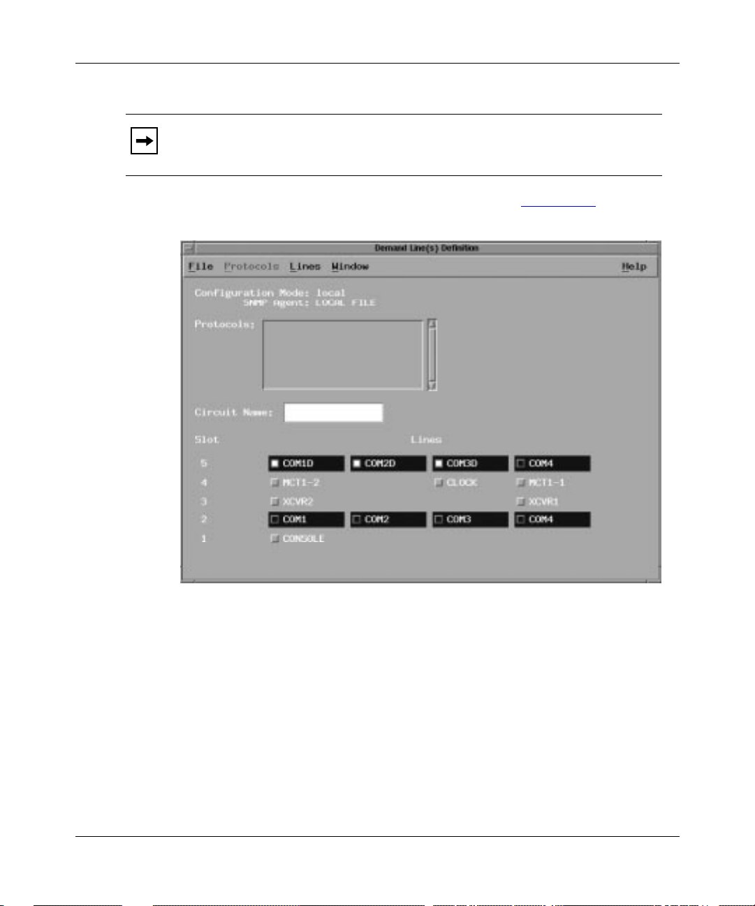
Getting Started
Note: You can use the same ID for a demand, backup, or bandwidth pool, but
you cannot use the same ID for two of the same type of pool.
Site Manager displays the Lines Definition window (Figure 1-4).
Figure 1-4. Demand Lines Definition Window for a Backbone Link Node
Click on an available COM connector to assign a line to the pool, but
4.
consider the following:
• Do not select any COM lines that you previously configured as leased
lines.
• The lines that you select for a demand pool must reside on the same slot.
• The lines that you select for a backup and bandwidth pool can reside
across slots.
114062 Rev. B 1-7
Page 38

Configuring Dial Services
Site Manager displays the Choose WAN Serial Interface Type window
(Figure
Figure 1-5. Choose WAN Serial Interface Type Window
1-5).
Note: On the BLN
®
and Backbone Concentrator Node (BCN®), the Choose
WAN Serial Interface Type window appears only for ports on an Octal Sync
Link Module. For all other modules, the Sync Line Media Type window
(Figure
5.
Site Manager: WAN Serial Interface Type parameter: page A-4
1-6) appears.
Accept the default, Sync, or click on Values and select Async.
If you plan to use Asynchronous PPP for your dial connections, you may w ant
to select Async for the WAN serial interface type. After selecting an interface
type, Site Manager displays the Sync Line Media Type window (Figure
or the Async Line Media Type window (Figure
1-7).
1-6)
1-8 114062 Rev. B
Page 39

Getting Started
Figure 1-6. Sync Line Media Type Window
Figure 1-7. Async Line Media Type Window
114062 Rev. B 1-9
Page 40

Configuring Dial Services
6. Click on OK to accept the line media default, Raise DTR.
At this point, you may want to select V.25bis or Hayes as the line media type
rather than accept the default.
For Hayes signaling, you need to specify a modem initialization string for
modem dialing (refer to Chapter 8 to modify modem parameters). For both
options, you need to configure an outgoing phone list (refer to “Creating an
Outgoing Phone List” on page 1-36).
Site Manager: Line Media Type parameter: page A-5
You return to the Lines Definition window. The letter D (demand), B
(backup), or W (bandwidth) appears next to the COM port to indicate what
type of line it is. Note that the router can use the same line for all three types
of pools. Asynchronous ports have an at sign (@) next to the connector name.
7. Select and configure more lines for the pool, if necessary.
8. Select File > Exit to exit the Lines Definition window (refer to Figure 1-4).
You return to the Pools window with three new buttons (Edit, Apply, and
Delete) that allow you to edit the new pool.
9. Now that you have set up a pool, do one of the following:
• Go to “Confi
guring Circuits” on page 1-19 to configure dial-up circuits.
• Go to the next section to add ISDN lines to the pool.
1-10 114062 Rev. B
Page 41

Creating Line Pools with ISDN Lines
Before creating a pool with ISDN lines, you need to select a port and designate it
as a BRI or PRI interface. Refer to the appropriate section for instructions:
Getting Started
•“Confi
•“Confi
guring BRI Lines”
guring PRI Lines” on page 1-12
Configuring BRI Lines
ISDN/BRI Net Modules are available only on the Access Node (AN®), Access
Stack Node (ASN™), Access Node Hub (ANH™), and Access Remote Node
(ARN™) hardware platforms. To configure BRI lines:
1. Begin at the Configuration Manager window (refer to Figure 1-1).
2. Click on an ISDN connector.
Site Manager displays the Port Application window (Figure
1-8).
Figure 1-8. Port Application Window
Accept the default, Dialup 2B+D, and click on OK.
3.
You return to the Configuration Manager window.
Site Manager: Port Application Mode parameter: page A-15
4. Repeat Steps 1 through 3 for each BRI line you want in the pool.
5. Go to “Adding ISDN Lines to a Pool” on page 1-16.
114062 Rev. B 1-11
Page 42

Configuring Dial Services
Configuring PRI Lines
PRI lines are available only on the ASN, BCN, and BLN hardware platforms
using the following link modules:
• Single or Dual Port Multichannel T1 Link Module (BLN and BCN)
• Dual Port Multichannel T1 Net Module (ASN)
• 120-ohm Single Port MCE1-II Net Module (BLN and BCN)
• 120-ohm Single or Dual Port MCE1-II Link Module (ASN)
• QMCT1 Link Module (BLN and BCN)
To configure PRI lines:
1. Begin at the Configuration Manager window (refer to Figure 1-1).
2. Click on an MCT1 or MCE1 connector.
Site Manager displays the Port Application window, which is similar to the
window shown in Figure
3. Select PRI for the Port Application Mode and click on OK.
1-8.
Site Manager: Port Application Mode parameter: page A-16
Site Manager displays the Clock Parameters window (Figure
1-9).
Figure 1-9. Clock Parameters Window
1-12 114062 Rev. B
Page 43

Getting Started
The clock parameters define the timing sources that apply to all connectors
and DS0 timeslots supported by the MCT1 and MCE1 Link Modules.
4. Click on OK to accept the default values for the clock parameters.
Site Manager displays the MCT1 Port Parameters window (Figure
1-10). The
MCE1 Port Parameters window has different parameters.
The port parameters apply to each of the 24 DS0 channels for MCT1 ports or
31 DS0 channels for MCE1 ports.
Figure 1-10. MCT1 Port Parameters Window
Click on OK to accept the default values for the port parameters.
5.
Note: In most cases, you can use the defaults for MCT1 and MCE1
parameters. If you want to modify these values, refer to Configuring WAN Line
Services.
Site Manager displays the PRI Logical Lines window (Figure
114062 Rev. B 1-13
1-11).
Page 44

Configuring Dial Services
Figure 1-11. PRI Logical Lines Window
For the first PRI interface you configure, the Timeslots window (Figure 1-12)
appears immediately after the PRI Logical Lines window.
Figure
1-12 shows the MCT1 Timeslots window. The MCE1 Timeslots
window is similar, but has 31 timeslots.
1-14 114062 Rev. B
Page 45

Getting Started
Figure 1-12. MCT1 Timeslots Window
Each PRI port supports up to 23 logical B channels for MCT1 ports or 30
logical B channels for MCE1 ports.
6. Click on Select All to change all timeslots to B channels.
If you purchased selective PRI service from your ISDN provider, you can
select individual timeslots. Select only the timeslots that the service provider
assigns to you. For example, if your provider assigns you timeslots
1 through 10, select slots 1 through 10 in the Timeslots window.
When you select a timeslot, a menu appears with two options (Figure 1-13).
Figure 1-13. Menu for PRI Timeslot
114062 Rev. B 1-15
Page 46

Configuring Dial Services
Select B Channel from the menu. The configured timeslot should read
B channel. Repeat the procedure for each timeslot you want to configure.
7. Click on OK.
You return to the PRI Logical Lines window.
8. Accept the default MTU size.
9. Click on Done.
Adding ISDN Lines to a Pool
To add ISDN BRI or PRI lines to a pool:
1. Begin at the Configuration Manager window (refer to Figure 1-1).
2. Select Dialup > Demand Pools, Backup Pools, or Bandwidth On Demand
Pools.
Site Manager displays a Pools window similar to Figure
3. Click on Add.
1-2 on page 1-6.
Site Manager displays the Pool Configuration window (refer to Figure
1-6).
page
4. Enter a pool ID and click on OK.
Site Manager: Demand/Backup/Bandwidth Pool ID parameter: page A-4
Site Manager displays the Lines Definition window (refer to Figure
5. Click on a previously configured ISDN, MCT1, or MCE1 port.
Site Manager displays the ISDN Switch Configuration window (Figure
1-3 on
1-4).
1-14).
1-16 114062 Rev. B
Page 47

Getting Started
Figure 1-14. ISDN Switch Configuration Window
Accept the default switch or select another switch for your network.
6.
Site Manager: Switch Type parameter: page A-16
7. Accept the defaults for the other parameters and click on Done.
Site Manager bypasses the ISDN Switch Configuration window for
subsequent ISDN lines. Subsequent chapters explain how to modify the
switch type.
After you select a switch, Site Manager displays the ISDN Logical Lines
window (Figure 1-15), where you define the number of B channels in the pool
and prioritize each channel.
114062 Rev. B 1-17
Page 48

Configuring Dial Services
Figure 1-15. ISDN Logical Lines Window
Figure 1-15 shows the ISDN Logical Lines window for BRI. For PRI, the
window is similar, but the parameter defaults are different.
8. Accept the defaults by clicking on OK.
You return to the Lines Definition window (refer to Figure
1-4). T o modify the
other switch parameters, refer to Chapter 8.
9. Select File > Exit to exit the Lines Definition window.
You return to the Pools window, which shows the configured pools. The
window has three new buttons: Edit, Apply, and Delete.
10. Repeat Steps 1 through 9 to add more lines to the pool.
For backup and bandwidth services, you can select lines across slots.
11. Go to the next section, “Configuring Circuits,” to configure dial-up
circuits.
1-18 114062 Rev. B
Page 49

Configuring Circuits
To configure dial-up circuits, refer to the appropriate section for instructions:
Getting Started
•“Creating
•“Creating
Demand Circuits”
Backup Circuits,” on page 1-25
•“Creating Bandwidth Circuits,” on page 1-28
When you create a PPP dial-up circuit, Site Manager creates a special PPP record
for the circuit, which identifies who is calling the router. This record is listed in
the PPP Interface Lists window as follows:
Interface for Dialup Lines
For more information about PPP, refer to Configuring PPP Services.
Creating Demand Circuits
To configure Frame Relay demand circuits, skip this section and go to Chapter 9.
To configure PPP demand circuits:
1. Begin at the Configuration Manager window (refer to Figure 1-1).
2. Select Dialup > Demand Circuits.
Site Manager displays the Demand Pools window, listing the new pools
(Figure
1-16).
Figure 1-16. Demand Pools Window Listing Configured Pools
114062 Rev. B 1-19
Page 50

Configuring Dial Services
3. Highlight the pool that you want the circuit to use and click on
PPP Circuits.
Site Manager displays the PPP Demand Circuits window (Figure
1-17).
Figure 1-17. PPP Demand Circuits Window
Click on Add to add a demand circuit.
4.
You return to the PPP Demand Circuits window, which shows the new circuit
and the defaults for each parameter (Figure
1-18). Site Manager also adds the
following buttons: Apply, Schedule, Phone Out, BW on Demand, and Delete.
1-20 114062 Rev. B
Page 51

Getting Started
Figure 1-18. Completed PPP Demand Circuits Window
Repeat Step 4 for each demand circuit you want to add.
5.
6. Keep the PPP Demand Circuits window open and go to the next section,
“Specif
114062 Rev. B 1-21
ying the Authentication Protocol Information.”
Page 52

Configuring Dial Services
Specifying the Authentication Protocol Information
For network security, the router must identify itself in the call setup message that
it sends to the remote router. The authentication protocols, CHAP and PAP, enable
the identification process. CHAP is the default protocol.
All lines in a pool must use the same authentication protocol.
To specify the CHAP information that the router uses when it calls a remote site:
1. Scroll down the PPP Demand Circuits window to the CHAP parameters.
2. Enter values for the CHAP Local Name and CHAP Secret parameters.
Each CHAP Local Name must be unique, but the CHAP Secret must be the
same for both sides of the connection.
Site Manager: CHAP Local Name parameter: page A-37
Site Manager: CHAP Secret parameter: page A-38
3. Go to the next section, “Specifying the Connection Mode.”
Specifying the Connection Mode
The connection mode determines which router places a call first, which prevents
two routers from establishing a demand circuit with each other at the same time.
To configure the connection mode:
1. Scroll down the PPP Demand Circuits window to the Connection Mode
parameter.
2. Select a value for the Connection Mode parameter. Collision Master is
the default.
If this router is set to Collision Master, we recommend that you set the router
at the other side of the connection to Collision Slave.
Site Manager: Connection Mode parameter: page A-28
3. Go to the next section, “Enabling a Protocol.”
1-22 114062 Rev. B
Page 53

Enabling a Protocol
In this section, you enable the Internet Protocol (IP). Refer to
Configuring IP Services for Site Manager windows and parameter descriptions.
To enable one or more protocols for a selected demand circuit:
1. From the top left corner of the PPP Demand Circuits window (refer to
Figure 1-17), select Protocols > Add/Delete.
Getting Started
Site Manager displays the Select Protocols window (Figure
Figure 1-19. Select Protocols Window
1-19).
Click on IP for this demand circuit and click on OK.
2.
Site Manager displays the IP Configuration window.
3. Enter an IP address and click on OK.
Site Manager: IP Address parameter; see
Configuring IP Services
Site Manager displays the IP Adjacent Host Configuration window.
114062 Rev. B 1-23
Page 54

Configuring Dial Services
4. Enter an IP adjacent host address and click on OK.
Site Manager: IP Adjacent Host parameter; see
Configuring IP Services
Site Manager displays the IP Adjacent Host Route window.
5. Click on OK to accept the defaults.
You return to the PPP Demand Circuits window (refer to Figure
Note: You cannot configure protocol prioritization for demand circuits
1-18).
running PPP multilink. Protocol prioritization modifies the order in which
packets are sent across the line. This could change the multilink-assigned order
of packets and cause problems with the data.
6. Do one of the following:
-- If you have ISDN lines in the pool, go to “C
reating an Outgoing Phone
List” on page 1-36.
-- If you have only Raise DTR lines in the pool, click on Done in the PPP
Demand Circuits window and go to “Setting
Up the Caller Resolution
Table” on page 1-40.
1-24 114062 Rev. B
Page 55

Creating Backup Circuits
To create a PPP backup circuit, you designate a single leased circuit, leased PPP
multiline circuit, or leased multilink circuit as a primary circuit. If the primary
circuit fails, the router activates a backup circuit to continue transmitting data.
To configure Frame Relay backup circuits, skip this section and go to Chapter 10.
To configure PPP backup circuits:
1. Begin at the Configuration Manager window (refer to Figure 1-1).
2. Select Dialup > Backup Circuits > PPP.
Getting Started
Site Manager displays the Primary Circuit Definition window (Figure
which lists the leased circuits that you have configured.
Figure 1-20. Primary Circuit Definition Window
1-20),
Highlight a circuit name and click on Cct (Circuit) Type.
3.
Site Manager displays the Circuit Options window (Figure
114062 Rev. B 1-25
1-21).
Page 56

Configuring Dial Services
Figure 1-21. Circuit Options Window
Select Primary for the Circuit Type parameter.
4.
Site Manager: Circuit Type parameter: page A-55
5. Enter the ID of the backup pool that you want this circuit to use.
Site Manager: Backup Pool ID parameter: page A-55
6. Click on OK.
You return to the Primary Circuit Definition window, which shows the new
circuit and the defaults for each parameter . Site Manager also adds the buttons
Apply, Schedule, and Phone Out.
7. Click on OK.
8. Repeat Steps 2 through 6 to configure more primary circuits.
9. Keep the Primary Circuit Definition window open and go to the next
section, “Specifying the Backup Mode
1-26 114062 Rev. B
.”
Page 57

Specifying the Backup Mode
The backup mode determines which router initiates a backup connection. To
specify the backup mode:
1. Scroll down the Primary Circuit Definition window to the Backup Mode
parameter.
2. Select a value for the Backup Mode parameter. Master is the default.
If this router is set to Master, the peer must be set to Slave.
Site Manager: Backup Mode parameter: page A-56
3. Go to the next section, “Specifying the Authentication Protocol
Information.”
Specifying the Authentication Protocol Information
For network security, the master router must identify itself when it calls the
remote router. The authentication protocols, CHAP and PAP, enable the
identification process. CHAP is the default protocol. All lines in a pool must use
the same authentication protocol.
Getting Started
To specify the CHAP information for the local router, do the following:
1. Scroll down the Primary Circuit Definition window to the CHAP
parameters.
2. Enter values for the CHAP Local Name and CHAP Secret parameters.
The CHAP Local Name must be unique, but the CHAP Secret must be the
same on both sides of the connection.
Site Manager: CHAP Local Name parameter: page A-37
Site Manager: CHAP Secret parameter: page A-38
3. Do one of the following:
-- If you have ISDN lines in the pool, go to “C
reating an Outgoing Phone
List” on page 1-36.
-- If you have only Raise DTR lines in the pool, click on Done and go to
“Setting
114062 Rev. B 1-27
Up the Caller Resolution Table” on page 1-40.
Page 58

Configuring Dial Services
Creating Bandwidth Circuits
There are two ways to enable bandwidth-on-demand service: designate a single
leased circuit or a leased multilink circuit as a bandwidth-on-demand circuit, or
assign a bandwidth pool to a demand circuit. If these circuits become congested,
the router provides up to 29 dial-up circuits to relieve the congestion, for a total of
30 dial-up lines for communication.
For configuration instructions, refer to the next section for leased circuits or to
“Adding Bandwidth
Configuring Leased Circuits as Bandwidth Circuits
You should have already configured PPP multilink for the leased circuits that you
will designate as bandwidth circuits.
To configure leased circuits as bandwidth circuits:
1. Begin at the Configuration Manager window (refer to Figure 1-1).
2. Select Dialup > Bandwidth On Demand Circuits.
Service for Demand Lines” on page 1-33.
Site Manager displays the Bandwidth-On-Demand Circuit Definition window
(Figure
1-28 114062 Rev. B
1-22), which lists the leased circuits that you previously configured.
Page 59

Getting Started
Figure 1-22. Bandwidth-on-Demand Circuit Definition Window
Highlight a circuit and click on Cct Type.
3.
Site Manager displays the Circuit Options window (Figure
Figure 1-23. Circuit Options Window
114062 Rev. B 1-29
1-23).
Page 60

Configuring Dial Services
4. Select Bandwidth on Demand for the Circuit Type parameter.
Site Manager: Circuit Type parameter: page A-75
5. Enter the ID of the bandwidth pool you want this circuit to use.
Site Manager: Bandwidth-on-Demand Pool ID parameter: page A-78
6. Keep this window open and go to the next section, “Specifying the
Bandwidth Mode.”
Specifying the Bandwidth Mode
The bandwidth mode determines whether the router serves as the congestion
monitor. The level of congestion instructs the router when to provide additional
circuits to carry data across the network.
To configure the bandwidth mode:
1. Scroll down the Circuit Options window to see the Bandwidth Mode
parameter.
2. Select a bandwidth mode. Non-Monitor is the default.
If this router is set to Non-Monitor, the peer must be set to Monitor.
Site Manager: Bandwidth Mode parameter: page A-76
Note the following for the Bandwidth Mode parameter:
• If you accepted the default, Non-Monitor:
Site Manager displays the Caller Resolution Info window, which you use
to enter the name of the remote router that this circuit supports. This
enables the local, non-monitor router receiving the call to identify the
remote router placing the call.
Enter values for the Caller Name and CHAP Secret parameters, then click
on OK.
Site Manager: Caller Name parameter: page A-103
Site Manager: CHAP Secret parameter: page A-103
1-30 114062 Rev. B
Page 61

Getting Started
• If you selected Monitor:
Site Manager does not prompt you for caller resolution information.
Howev er , if this is the first monitor circuit associated with a pool that uses
multiple slots, Site Manager displays the Preferred/Reserved Slots for
BOD Pool window (Figure
Figure 1-24. Preferred/Reserved Slots for BOD Pool Window
1-24).
Enter a number for the Preferred Bandwidth Slot and Reserved
Bandwidth Slot parameters and click on OK.
Site Manager: Preferred Bandwidth Slot parameter: page A-80
Site Manager: Reserved Bandwidth Slot parameter: page A-81
You return to the Circuit Options window (refer to Figure
3. Click on OK to exit the Circuit Options window.
1-23).
You return to the Bandwidth-on-Demand Circuit Definition window (refer to
Figure 1-22).
4. Keep the Bandwidth-on-Demand Circuit Definition window open and go
to the next section, “Specifying t
114062 Rev. B 1-31
he Authentication Protocol.”
Page 62

Configuring Dial Services
Specifying the Authentication Protocol
For network security, the router must identify itself in the call setup message that
it sends to the remote router. The authentication protocols, CHAP and PAP, enable
the identification process. CHAP is the default protocol.
All lines in a pool must use the same authentication protocol.
To specify the CHAP information for the local router:
1. Scroll down the Bandwidth-on-Demand Cir cuit Definition windo w to the
CHAP parameters.
2. Enter values for the CHAP Local Name and CHAP Secret parameters.
The CHAP Local Name must be unique, but the CHAP Secret must be the
same on both sides of the connection.
Site Manager: CHAP Local Name parameter: page A-37
Site Manager: CHAP Secret parameter: page A-38
3. Do one of the following:
-- If you have ISDN lines in the pool, go to “C
reating an Outgoing Phone
List” on page 1-36.
-- If you have only Raise D TR lines in the pool, click on Done in the
Bandwidth-on-Demand Circuit Definition window and go to “Setting
Up
the Caller Resolution Table” on page 1-40.
1-32 114062 Rev. B
Page 63

Adding Bandwidth Service for Demand Lines
If the demand line becomes congested, the router can provide 29 additional
dial-up lines to reduce congestion. To do this, you enable bandwidth service for
the demand line by associating it with a configured bandwidth pool.
To add bandwidth service for a demand circuit:
1. Select Dialup > Demand Circuits > PPP Circuits.
Getting Started
Site Manager displays the PPP Demand Circuits window (Figure
1-25).
Figure 1-25. PPP Demand Circuits Window
Click on BW on Demand.
2.
Site Manager displays the Enter a BOD Pool window (Figure
114062 Rev. B 1-33
1-26).
Page 64

Configuring Dial Services
Figure 1-26. Enter a BOD Pool Window
Enter the ID number of a configured bandwidth pool.
3.
4. Click on OK.
Site Manager displays the BOD Configuration window (Figure
1-27). The
parameters in this window determine whether the router acts as the
monitor router, which means that it monitors congestion on the line, and
whether the router activates additional lines to relieve congestion.
1-34 114062 Rev. B
Page 65

Getting Started
Figure 1-27. BOD Configuration Window
Click on OK to accept the defaults.
5.
You return to the PPP Demand Circuits window.
6. Click on Remove BOD only if you want to remove bandwidth service for
the demand circuit; otherwise, go to the next step.
7. Do one of the following:
-- If you have ISDN lines in the pool, go to “C
reating an Outgoing Phone
List” on page 1-36.
-- If you have only Raise DTR lines in the pool, click on Done and go to
“Setting
114062 Rev. B 1-35
Up the Caller Resolution Table” on page 1-40.
Page 66

Configuring Dial Services
Creating an Outgoing Phone List
For ISDN, V.25bis, and Hayes connections, the router uses the outgoing phone list
to place a call to a remote router. In this chapter, we assume that your modem
connections are Raise DTR, which means that the phone numbers are
programmed directly into the modem. Therefore, you only need to set up an
outgoing phone list if you have configured ISDN connections.
Outgoing phone lists are associated with a specific circuit, not with the physical
line. The lines in the pool may be used by many circuits, which is why the
telephone numbers are part of each circuit’s configuration and not the line’s
configuration.
To create an outgoing phone list:
1. Begin at the PPP Demand Circuits, Primary Circuit Definition, or
Bandwidth-on-Demand Circuit Definition window.
2. Select a circuit and click on Phone Out.
Site Manager displays the Outgoing Phone List window (Figure
Figure 1-28. Outgoing Phone List Window
1-28).
1-36 114062 Rev. B
Page 67

Getting Started
Click on Add to display the Phone Number window (Figure 1-29).
3.
Figure 1-29. Phone Number Window
Enter a phone number for the Phone Number parameter, and an
4.
extension, if any, for the Phone Ext/Subaddr parameter.
Site Manager: Phone Number parameter: page A-96
Site Manager: Phone Ext/SubAddr parameter: page A-97
5. Click on OK.
You return to the Outgoing Phone List window with the phone number
parameters and the phone list filled in.
6. Accept the defaults for Phone Number Type, ISDN Numbering Type, and
ISDN Numbering Plan, unless your service provider instructs otherwise.
Site Manager: Phone Number Type parameter: page A-89
Site Manager: ISDN Numbering Type parameter: page A-89
Site Manager: ISDN Numbering Plan parameter: page A-90
7. Click on Done when you finish entering phone numbers.
8. For ISDN configurations, go to the next section; otherwise, go to
“Setting
114062 Rev. B 1-37
Up the Caller Resolution Table” on page 1-40.
Page 68

Configuring Dial Services
Creating the Local Phone List (ISDN only)
A local phone number identifies the local router when it places a call to a remote
router. The router includes its own phone number in the ISDN outgoing call setup
message. This number, along with Service Provider IDs (SPIDs) in the United
States and Canada, also identifies the router to the ISDN switch so that the switch
can activate the circuit. Your ISDN service provider assigns this number.
You must configure local phone numbers if you use the Bandwidth Allocation
Protocol (BAP) with bandwidth service across ISDN connections. The router
designated as the non-monitor uses the local phone number to identify additional
lines to the peer.
To create a local phone list:
1. Begin at the Configuration Manager window (refer to Figure 1-1).
2. Select Dialup > Local Phone Numbers.
Site Manager displays the ISDN Local Phone Lines window (Figure
Figure 1-30. ISDN Local Phone Lines Window
Click on Local Phones.
3.
Site Manager displays the ISDN Local Phone Numbers window
(Figure
1-31).
1-30).
1-38 114062 Rev. B
Page 69

Getting Started
Figure 1-31. ISDN Local Phone Numbers Window
The SPID parameter appears only for switches used in the United States and
Canada.
4. Click on Add.
Site Manager displays the Phone Number window (Figure
Figure 1-32. Phone Number Window
114062 Rev. B 1-39
1-32).
Page 70

Configuring Dial Services
5. Enter a local phone number and a subaddress, if any.
Site Manager: Directory Number parameter: page A-85
Site Manager: Ext/SubAddr parameter: page A-85
6. Click on OK to accept the defaults for the other parameters.
You return to the ISDN Local Phone Numbers window, which shows the new
phone entry.
7. Repeat the procedure for each phone number you want to add.
8. Click on Done until you return to the Configuration Manager window.
9. Go to the next section, “Setting Up the Caller Resolution Table.”
Setting Up the Caller Resolution Table
For network security, all three dial services use a PPP identification mechanism to
determine who is calling the router. PPP performs this identification process using
one of two authentication protocols, CHAP or PAP. CHAP is the default protocol.
To identify an incoming remote caller, you enter the name and CHAP secret of
each remote caller in a caller resolution table, and associate each name with a
local demand, primary, or bandwidth circuit. When a router receives an incoming
call, it checks the caller resolution table for an entry that identifies the caller. If the
caller is authorized, the local router activates a circuit.
To configure the caller resolution table:
1. Begin at the Configuration Manager window (refer to Figure 1-1).
2. Select Dialup > Caller Resolution Table.
Site Manager displays the Caller Resolution Table window (Figure
1-40 114062 Rev. B
1-33).
Page 71

Getting Started
Figure 1-33. Caller Resolution Table Window
3. Click on Add to add an entry to the table.
Site Manager displays the Caller Name and Secret/Password window
(Figure
Figure 1-34. Caller Name and Secret/Password Window
114062 Rev. B 1-41
1-34).
Page 72

Configuring Dial Services
4. Enter the name and CHAP secret of the remote router.
The CHAP secret must be the same for routers on both sides of the circuit.
Site Manager: Caller Name parameter: page A-103
Site Manager: CHAP Secret parameter: page A-103
The Caller Name parameter identifies a remote router. Do not confuse this
parameter with the CHAP Local Name parameter, which identifies the local
router, that is, the router you are currently configuring.
5. Click on OK.
Site Manager displays the Local Circuit List window (Figure
1-35), which
lists the demand, primary, or bandwidth circuits that you have configured.
Figure 1-35. Local Circuit List Window
Highlight the local circuit that the router should activate when it r ecei ves
6.
a call from the remote router (specified in the Caller Name parameter).
Site Manager: Local Circuit parameter: page A-104
7. Click on OK.
You return to the caller resolution table window. When you select a caller
name in the window, the parameters display the caller’s information.
8. Click on Done when you finish adding table entries.
1-42 114062 Rev. B
Page 73

What to Do Next
Now that you have completed the steps in this chapter, your dial service should be
operating. To further modify your configuration, refer to the appropriate chapter
for instructions:
• Chapter 2 provides an overview of each service.
• Chapter 3 provides an overview of ISDN.
• Chapter 4 describes Bay Networks implementation common to all dial
services.
• Chapters 5 through 7 describe Bay Networks implementation of
dial-on-demand, dial backup, and bandwidth-on-demand, respectively. These
chapters provide information to help you make appropriate customizing
choices.
• Chapters 8 through 13 provide instructions for customizing your
configuration.
• Appendix A contains parameter descriptions for all dial services.
Getting Started
• Appendix B provides some basic configuration examples.
• Appendix C lists parameter defaults for all dial services.
• Appendix D explains how to order ISDN lines in the United States.
• Appendix E lists the AT initialization commands for the ARN.
114062 Rev. B 1-43
Page 74

Page 75

Chapter 2
Dial Services Overview
A dial service provides access to a central switched network for remote users,
such as people in branch offices, telecommuters, and sales people in the field. To
make these remote connections, dial services use dial-up lines (also called
switched lines), which are activated only when needed.
If you send a limited amount of data or your data transmission is intermittent,
dial-up lines can be less expensive than leased lines, and they improve network
performance and flexibility.
Page 76

Configuring Dial Services
The names of the dial services are sometimes abbreviated in this manual.
able 2-1 lists the full and abbreviated names of each dial service.
T
Table 2-1. Dial Service Names
Full Name Abbreviated Name
Dial-on-demand Demand
Dial backup Backup
Bandwidth-on-demand Bandwidth
All three dial services work over Public, Switched Telephone Networks (PSTNs)
such as a standard telephone network, a switched 56 Kb/s network, and an
Integrated Services Digital Network (ISDN) (Figure
2-1).
PSTN
Modem
Router
*You only need a terminal adapter if your router does not have built-in ISDN capability.
If your router has an ISDN/BRI module or an MCT1 or MCE1 link module installed,
along with ISDN software, you can connect to an ISDN network directly.
DSU/CSU
Terminal*
adapter
Dial-up line
Dial-up line
Dial-up line
Dial-up line
Switched
56 Kb/s
network
ISDN
DS0005A
Figure 2-1. Example of Dial Access to a Switched Telephone Network
2-2 114062 Rev. B
Page 77

Network Access Methods and Services
The router initiates, monitors, and terminates dial-up connections using a modem
or ISDN terminal adapter that supports Raise DTR, V.25bis, or Hayes signaling,
or a router with a built-in ISDN interface connected directly to an ISDN network.
If the router has internal ISDN capability, you do not need external dial devices.
Note: For BRI service, you need a network terminator 1 (NT1) to connect to
an ISDN network. With the exception of the ARN, the router’s ISDN/BRI
Module does not include an internal NT1, so you or your service provider
must supply it.
All three dial services enable the router to access a switched network as follows:
• Integrated ISDN capability -- Provides a BRI or PRI for digital connectivity
from the router to the destination device, replacing standard analog phone
lines. Using signals on an ISDN line, the router instructs the network to set up
a call to a particular destination. ISDN capability eliminates the need for dial
devices such as modems, because you no longer need to convert digital
signals to analog. An ISDN network also allows you to send data, voice, and
video over the same digital line.
Dial Services Overview
• Raise DTR -- A signaling method that enables access to the network by
preprogramming the destination phone numbers into the dial device (modem
or ISDN terminal adapter). Raise DTR signaling works with the following
interfaces: X.21, V.35, RS-232, and RS-422.
• V.25bis -- A signaling method that enables access to the network by passing
the destination phone numbers from the router to the dial device (modem or
ISDN terminal adapter). This method lets the dial device support connections
to multiple destinations. V.25bis signaling works with the following
interfaces: X.21, V.35, RS-232, and RS-422.
• Hayes -- A signaling method that enables network access by passing the
destination phone numbers from the router to the dial device (modem or
ISDN terminal adapter). Using Hayes signaling, the router sends an AT
initialization command to interact with the dial device. The ARN internal V.34
modem uses Hayes signaling. Hayes signaling works with RS-232 interfaces.
The method you choose depends on your application, network resources, and the
type of network to which you are connecting. ISDN, a complex networking
technology, is further explained in Chapter 3.
114062 Rev. B 2-3
Page 78

Configuring Dial Services
Dial-on-Demand Service
Dial-on-demand service enables you to establish a network connection only when
the router has data to send across the network, or when you dynamically configure
the router to establish a connection. By using dial-up lines, you significantly
reduce the high costs associated with leased lines, which connect remote locations
even if there is no data to transmit or receive.
T o implement dial-on-demand, the router establishes a demand circuit (that is, the
logical connection) over a physical line. The router establishes a demand circuit
when
• The router has data to send across the circuit.
• You specify a time of day to activate the circuit.
• You enable the Force Dial parameter, which instructs the router to force a
connection.
The router terminates the circuit when
• The configured inactivity time expires because the router is not sending or
receiving data.
• You schedule a time of day to take the circuit down.
• You enable the Force Take Down parameter, which instructs the router to
force the termination of a connection.
Refer to “Acti
Dial-on-demand is supported on asynchronous (RS-449), synchronous (RS-449,
V.35, RS-422, and X.21), and ISDN interfaces. Figure
connecting two routers. When the router has data to transmit or when you
configure the router to bring up a demand circuit, the router instructs the dial
device to establish a connection.
2-4 114062 Rev. B
vating Demand Circuits” on page 2-9 for more information.
2-2 shows a demand line
Page 79

Dial Services Overview
Data arrives at the New York router, but the final destination
is Dallas. A port in the demand pool transmits the data.
Los Angeles
Dial
device
Chicago
Dial
device
Dallas
Dial
device
DS0013A
Demand pool 1:
Slot 2
New York
Back of
router
Dial
device
Dial
device
Figure 2-2. Dial-on-Demand Service
Demand Lines and Pools
Demand lines provide the physical connections over which the demand circuits
transmit and receive data. To maximize the number of circuits that can be active
simultaneously, you establish a demand pool.
A demand pool is a group of one or more lines that reside in the same slot on the
router. You identify each demand pool by assigning a demand pool ID. Lines in a
demand pool can connect to a modem, directly to a PSTN (using the ARN with
the V.34 Modem Adapter Module), or directly to an ISDN network (using a router
with internal ISDN capability).
You can combine asynchronous, synchronous, and ISDN interfaces in a single
pool. The synchronous interfaces can use Raise DTR or V.25bis signaling for
modem connections. The asynchronous interfaces can use Raise DTR, V.25bis, or
Hayes signaling for modem connections. Hayes signaling requires that you use AT
modem commands to send dialing instructions to the modem. The ISDN lines use
ISDN signaling for network connections.
114062 Rev. B 2-5
Page 80

Configuring Dial Services
How Demand Lines, Pools, and Circuits Work Together
When you create demand circuits, you assign a demand pool ID to each circuit.
Note that many demand circuits can use the same demand pool and, therefore, can
use the same lines in that pool. The line itself does not have a specific network
address; it is the circuit that has the associated network address.
When the router has data to send across a demand circuit, the circuit searches for
an available demand line from its associated demand pool. When it finds an
available line, the router establishes a dial-up connection to the remote router. The
router terminates the connection when there is no more data to send or receive,
when you manually take down the connection, or the scheduled time for an active
connection expires.
Figure
2-3 shows the relationship between demand lines, pools, and circuits using
PPP as the data link layer protocol.
Demand pool 1:
New York
Configuration of the New York router
Circuit 1 – 192.32.14.1
(the local interface to Los Angeles)
Circuit 2 – 192.32.15.1
(the local interface to Chicago)
Circuit 3 – 192.32.16.1
(the local interface to Dallas)
Line 1
Dial
device
Dial
device
Line 2
192.32.14.0
192.32.15.0
192.32.16.0
Circuit 1 – 192.32.14.2
Dial
device
Los Angeles
Circuit 2 – 192.32.15.2
Dial
device
Chicago
Circuit 3 – 192.32.16.2
Dial
device
Dallas
DS0014A
Figure 2-3. Example of Demand Lines, Pools, and Circuits
2-6 114062 Rev. B
Page 81

In Figure 2-3, three circuits share two physical lines that make up Demand pool 1.
Note that only two of the circuits using Demand pool 1 can be active
simultaneously because only two modems are available. The IP addresses are
associated with each circuit, not with the physical line.
In addition to assigning a demand pool ID to each circuit, you can assign protocol
interfaces and configure phone lists for use with V.25bis, Hayes, and ISDN
signaling. Refer to Chapter 12 for more information.
Demand Circuit Protocols
The protocol for a demand circuit can be either PPP or Frame Relay. A Frame
Relay demand circuit may have any number of service records and PVCs.
Typically, Frame Relay connections are used with ISDN lines. PPP and Frame
Relay circuits can use the same demand pool.
Dial Services Overview
Figure
2-3 shows an example of a PPP demand circuit over modem lines. Figure
2-4 shows a Frame Relay demand circuit over ISDN lines.
Frame Relay network
Router A
Router B
Router C
MODEM
BRI
PRI
Raise DTR/V.25bis
Frame
Relay
switch
Frame
Relay
switch
Frame
Relay
switch
T1/HSSI/SYNC
Frame
Relay
switch
Key
Leased line
Dial-up line
Figure 2-4. Dial-on-Demand Connection over a Frame Relay Network
Router D
DS0033A
114062 Rev. B 2-7
Page 82

Configuring Dial Services
In Figure 2-4, remote Routers A, B, and C are connecting to the central Router D
through a Frame Relay network, dialing into the network across ISDN lines.
Router D connects to the network across a leased line.
The permanent virtual circuits (PVCs) in this network can be either fully meshed
or non-fully meshed, allowing Routers A, B, C, and D to connect to one another.
With the dial connection between the routers and the Frame Relay network, each
router can dial into the network and communicate with one another, pro vided that
the PVCs are set up properly and the physical and logical connections are active.
Configuring Frame Relay to Work Optimally with Dial-on-Demand
How Frame Relay demand circuits operate depends on how your Frame Relay
service provider defines the user network interface (UNI), the point between the
router and the service provider . The service pro vider defines the UNI dynamically
or statically.
If the UNI is dynamic, it changes for each call. This means that the PVCs may be
different for each call, but they direct data to the same destination. The router
initially learns the PVCs when it calls the Frame Relay switch. If the UNI is static,
the user has defined the PVCs and can configure them for the router. The UNI
remains the same for all calls.
For a Frame Relay demand configuration to work well, follow these guidelines:
• You must have a PVC configured before you place a call.
For data to activate a demand circuit (instead of using Force Dial), the router
must learn at least one PVC from the Frame Relay switch before it can place a
call. However, to learn the PVCs, the router must call the switch, which it
cannot do.
For a dynamic UNI, you need to statically configure at least one PVC on the
router that is not configured for the switch. The static PVC acts as a “fake”
PVC that the router uses only to place an initial call to the switch. To
configure a static PVC, you set the Frame Relay Data Link Connection
Identifier (DLCI) to a number other than the number the switch provider
assigns, assuming you know the range of possible DLCIs. The static PVC is
still valid if you happen to use a number that the switch provider uses. Refer
to Configuring Frame Relay Services for information about configuring
PVCs.
For a static UNI, the user configures the PVCs. A “fake” PVC is unnecessary.
2-8 114062 Rev. B
Page 83

• For a dynamic UNI, use the default Frame Relay service record. This service
record holds all PVCs that the router learns dynamically.
• Choose a network layer protocol that can retransmit data between the PVC
and the network if the data is lost.
Although the router makes a dial connection and starts sending data, the
PVCs do not always activate immediately. Consequently, you might lose data
during the first part of the transmission. Therefore, it is important to use
protocols that can account for this situation and ensure that any lost data can
be sent again. We strongly recommend using Internet Protocol (IP) or Internet
Protocol Exchange (IPX).
• If the remote routers in your network are using IP , ensure that they also use the
Address Resolution Protocol (ARP) and not Inverse ARP. This enables the
local router to learn address information.
Activating Demand Circuits
The router activates a demand circuit when
Dial Services Overview
• The router has data to send across the circuit.
When the router has data to transmit, it automatically selects one of the
demand lines from the circuit’s associated demand pool. As long as data is
going across the line, the end-to-end connection remains active.
• You enable the Force Dial parameter.
To activate a line immediately, you configure the Force Dial parameter to
force the router to initiate a connection, regardless of whether there is data
activity. To configure this parameter, refer to Chapter 9.
• You specify a time of day to activate the circuit.
Using the Schedule option, you can schedule the circuit’s availability for a
specific day and time. The schedule parameters are part of the circuit’s
configuration (refer to Chapter 9). The Schedule option also allows you to
specify whether the router uses the Inactivity Time parameter to dynamically
deactivate the connection.
The router does not accept incoming calls or activate Frame Relay demand
circuits if there is an incoming call from the Frame Relay network. The router
answers an incoming call only over a PPP circuit.
114062 Rev. B 2-9
Page 84

Configuring Dial Services
The Frame Relay switch does not activate PVCs and configured DLCIs until the
router receives data from the demand circuit and exchanges Data Link Control
Management Interface (DLCMI) status messages with the switch. For more
information about Frame Relay, refer to Configuring Frame Relay Services.
Terminating Demand Circuits
The router deactivates the demand circuit when
• You enable the Force Take Down parameter.
To deactivate a force dial connection, you configure the Force Take Down
parameter, which instructs the router to clear the connection. To learn how to
configure this parameter, refer to Chapter 9.
• You schedule the circuit to come down.
Using the Schedule option, you can schedule the circuit’s availability for a
specific day and time. The schedule parameters are part of the circuit’s
configuration (refer to Chapter 9). The Schedule option also allows you to
configure whether the router uses the Inactivity Time parameter to
dynamically deactivate the connection.
• The inactivity time expires.
To deactivate the connection, you can configure the Inactivity Time
parameter, which dynamically terminates the connection after a specified
amount of time elapses without data activity. If there is data going across the
line, the inactivity time resets and the connection remains active.
T o ensure that a connection is not up longer than necessary, you can configure
traffic filters that allow specific types of data to go across a line without
resetting the inactivity time.
For PPP connections, the router does not consider Link Quality Report
(LQR), Link Control Protocol (LCP), and periodic CHAP messages as data,
so these messages do not reset the inactivity timer.
For Frame Relay circuits, DLCMI messages and other signaling packets are
not treated as data, so they do not reset the inactivity timer. The router usually
terminates Frame Relay demand connections, not the Frame Relay network.
• The Frame Relay DLCMI fails.
If the DLCMI messages cannot be exchanged across the Frame Relay demand
circuit, the router deactivates the circuit.
2-10 114062 Rev. B
Page 85

Dial Services Overview
Bandwidth-on-Demand Service for Congested Demand Lines
To relieve congestion across a demand line, you can use up to 29 additional lines
from an existing bandwidth-on-demand pool, providing a total of 30 lines for
communication. This feature is only for demand configurations that use PPP as
the data link-layer protocol. Adding bandwidth to a congested demand line
benefits time-critical applications that require data to reach its destination
efficiently.
To enable bandwidth-on-demand service, you associate the demand circuit with a
bandwidth-on-demand pool, then you configure parameters that monitor
congestion across the line.
Once you enable bandwidth-on-demand service, the router determines that the
demand line is congested when the traffic over the line exceeds a certain
user-configured threshold. The router that is configured as the congestion monitor
then searches for an available line from the bandwidth pool that you associate
with this demand circuit.
Lines in a bandwidth-on-demand pool can reside across slots, so you need to
designate each slot as either preferred or reserved. This determines the order in
which the router searches the slots for available lines; the preferred slot is first and
the reserved slot is second. If these slots have no available lines, the router
automatically uses the local slot. The local slot is the slot containing the first
demand line that was activated. When the router activates additional lines, they
adopt the configuration of the congested demand circuit.
PPP multilink is the protocol that enables the router to use multiple lines
simultaneously to transmit data. Multilink enables the router to use lines at
different speeds and to ev enly distribute data across those lines. When you enable
multilink, you can configure a set of links between two peers into a single bundle.
The actual number of lines in a multilink bundle depends on hardware platform
constraints, total bundle speed, the speed of each link in the bundle, and the type
of traffic you are sending.
For PPP demand connections across ISDN lines, you can manage the allocation of
bandwidth for a multilink bundle by enabling the PPP Bandwidth Allocation
Protocol (BAP). This protocol is available only after bandwidth service is set up.
For more information about BAP, refer to Chapter 7.
114062 Rev. B 2-11
Page 86

Configuring Dial Services
Figure 2-5 illustrates how additional switched lines provide more bandwidth for a
congested demand line.
New York City
ISDN
Key
Initial demand
line
Additional lines
from a bandwidth pool
Figure 2-5. Additional Lines for a Dial-on-Demand Connection
Boston
DS0004A
2-12 114062 Rev. B
Page 87

Dial Backup Service
Dial backup service lets you configure backup lines for failed primary lines. A
primary line is a leased line, a leased multiline (Standard and PPP only), or a
leased multilink connection. This leased line acts as the physical connection over
which the leased circuit (the logical connection) carries traffic. You designate
these leased circuits as primary circuits, which instructs the router to provide
backup service if the primary line and circuit fail.
If a primary circuit fails and you configure dial backup service for that circuit, the
router activates an a vailable backup line. When the primary circuit is restored, the
router reroutes all traffic from the backup circuit to the primary circuit and clears
the dial backup connection.
Dial backup is supported on asynchronous lines (RS-449), synchronous lines
(RS-449, V.35, RS-422, and X.21), and ISDN interfaces.
able 2-2 lists the primary and backup lines you can configure.
T
Table 2-2. Primary and Backup Lines
Dial Services Overview
Line Type
Primary Any leased line up to T1/E1 rates, including multiline (Standard and
PPP only) and multilink connections. Frame Relay multiline circuits
cannot be dial backup primaries.
Frame Relay PVCs
Backup Any WAN line including ISDN B channels. Lines must be in the dial
backup pool.
Table 2-3 lists the protocols for each type of primary and backup circuit.
Table 2-3. Primary and Backup Circuit Protocols
If the primary circuit’s protocol is The backup circuit’s protocol can be
Standard Async or Sync PPP only
PPP Async or Sync PPP only
Frame Relay -- backing up only one PVC Async or Sync PPP only
Frame Relay -- backing up the entire Frame
Relay interface
114062 Rev. B 2-13
Frame Relay only
Page 88

Configuring Dial Services
Circuit Backup versus Link Backup
When you select PPP or Frame Relay for the backup circuit, you determine
whether the router performs circuit backup or link backup.
Circuit backup is a point-to-point backup connection. One circuit is backed up at a
time, instead of an entire interface. When you back up a point-to-point primary
circuit (Standard, PPP, or a single Frame Relay PVC), the protocol for the backup
circuit is PPP.
Figures 2-
6 and 2-7 show examples of circuit backup. Figure 2-6 shows a
Standard primary circuit aided by a PPP backup circuit. Figure
primary circuit aided by a PPP backup circuit.
Note: F or circuit backup of a single Frame Relay PVC, the backup line passes
through the switched network only, bypassing the Frame Relay network.
If either primary line fails, the modem at Central site A
can connect to router B or C via a backup circuit.
Central site A
Router
Key
Primary line
Backup line
Modem
Remote site C
Router
PSTN
Modem
Modem
2-7 shows a PPP
Remote site B
Router
DS0020A
Figure 2-6. PPP Backup over a PSTN
2-14 114062 Rev. B
Page 89

Dial Services Overview
Router Router
Primary leased line
Dial backup line
ISDN
DS0021A
Figure 2-7. PPP Backup over an ISDN Network
Link backup is a multiple-circuit backup, which means that the entire interface is
backed up. To back up all PVCs for a Frame Relay interface, you configure Frame
Relay across the backup circuit.
Figure
2-8 shows an example of link backup.
Failure point
Remote site router (R1)
Frame Relay
interface
BRI
Frame Relay
network
PRI
ISDN
network
Central site router (R2)
Group mode PVCs
Key
Primary PVCs
Backup PVCs
DS0026A
Figure 2-8. Link Backup for a Frame Relay Network
114062 Rev. B 2-15
Page 90

Configuring Dial Services
In Figure 2-8, if the Frame Relay link fails at router R1, the router activates a
backup connection through the ISDN network, then back through the Frame
Relay network to the destination. The backup connection to the Frame Relay
network uses a different network interface and PVCs than the primary connection.
Once the primary line recovers and the Frame Relay switch responds to router
R1’s DLCMI status requests, router R1 terminates the backup connection.
Note: A primary circuit cannot use link and circuit backup simultaneously.
Knowing When the Primary Line Fails
Depending on the protocol for the primary and backup circuit, the router
determines that the primary circuit failed in one of the following ways:
• No Breath of Life (BofL) messages in the BofL
(Standard and PPP)
For Standard and PPP, Site Manager automatically enables BofL messages on
each primary line and disables them on each backup line. BofL messages
verify that the line is operational. The router determines that the primary line
has failed when it stops receiving packets within the BofL time period.
You configure the BofL timer using the synchronous line parameter BofL
Timeout. See Configuring Line Services for more information.
• No DLCMI messages (Frame Relay primary/Frame Relay backup)
When Frame Relay is the protocol for the backup circuit, the router performs
link backup. For link backup, the router knows that the primary failed when it
no longer receives DLCMI messages from the switch. These messages
communicate information about the interface and the status of each PVC.
The router may also rely on modem signals to determine if the primary circuit
failed. If you rely on modem signals, you must set the Sync Polling parameter
to Enable, which instructs the router to monitor modem signals. (Refer to
Configuring Line Services for more information about the Sync Polling
parameter.) In addition, you must use the proper synchronous cable to connect
to the primary line’s modem or CSU/DSU. Refer to the Cable Guide for
Routers and BayStream Platforms.
time period
2-16 114062 Rev. B
Page 91

• A-bit notification (Single Frame Relay PVC primary/PPP backup)
If only one Frame Relay PVC is being backed up by PPP, the router performs
circuit backup. For circuit backup, the Frame Relay service provider must
support A-bit notification, which tells the router the status of the PVC. This
enables the router to back up the PVC if it fails. W ithout A-bit notification, the
remote side of the PVC is never notified when the local side of the PVC has
terminated, making dial backup service impossible.
Backup Lines and Pools
A backup line is an alternate line that carries data if the primary line fails. It is
advantageous, therefore, to have one or more backup lines to ensure data
transmission. To assign one or more backup lines to a primary line, you establish a
backup pool.
A backup pool is a collection of lines that the primary circuits can use. Each
backup pool is identified by a backup pool ID.
The lines in a backup pool can reside in any slot on the router that supports WAN
lines; therefore, the pool can span multiple slots. Lines in a backup pool can
connect to a modem, directly to a PSTN (using the ARN with the V.34 Modem
Adapter Module), or directly to an ISDN network (using a router with integral
ISDN capability).
Dial Services Overview
You can combine asynchronous, synchronous, and ISDN interfaces in a single
pool. The synchronous interfaces can use Raise DTR or V.25bis signaling for
modem connections. The asynchronous interfaces can use Raise DTR, V.25bis, or
Hayes signaling for modem connections. Hayes signaling requires that you use AT
modem commands to send dialing instructions to the modem. The ISDN lines use
ISDN signaling for network connections.
114062 Rev. B 2-17
Page 92

Configuring Dial Services
How Backup Lines, Pools, and Circuits Work Together
For each leased circuit that needs a backup circuit, you designate that circuit as a
primary circuit and assign it a backup pool ID. If the primary circuit fails, the
router activates the backup line to carry the backup circuit. If your network uses a
multiline or multilink primary , the backup line is activ ated when the last line in the
multiline or multilink bundle fails. You must first configure a leased circuit and a
backup pool before you can configure primary and backup circuits.
Figure
2-9 shows how backup lines, pools, and circuits work together. The router
in San Diego has two leased lines, one going to a router in Phoenix and the other
to a router in San Francisco. The circuits for each of these destinations are
associated with Backup Pool 1. If either of these leased lines fails, the San Diego
router activates Backup Line 1 from Backup Pool 1 to continue routing traffic to
the destination.
128.32.17.2
Backup pool 1:
Backup line 1
San Diego
Configuration of the San Diego router
Circuit 1 - 128.32.17.1
(the local interface to Phoenix)
Circuit 2 - 128.32.18.1
(the local interface to San Francisco)
128.32.17.0
ISDN
128.32.18.0
Phoenix
128.32.18.2
San Francisco
DS0029A
Figure 2-9. Example of Backup Pools, Lines, and Circuits
You can assign the same backup pool ID to more than one primary circuit. If you
want only one backup line dedicated to a primary circuit, then you should
configure only one line in a pool and assign that pool exclusively to that circuit.
2-18 114062 Rev. B
Page 93

Configuration of the Backup Circuit
The configuration of the backup circuit depends on the protocol for that circuit. If
Standard or PPP is running over the primary circuit, the backup circuit inherits the
primary’s network layer address configuration. Unlike the network layer address
configuration, the data link layer configuration can be unique.
If Frame Relay is running over the primary circuit, the backup circuit can inherit
the primary’s configuration or it can use its own configuration. When the Frame
Relay primary and backup circuit use the same configuration, it is called the
shared configuration. The shared configuration allows a backup circuit to use the
same network layer address as the primary circuit. The backup circuit’s data link
layer configuration (PVCs, DLCIs, and filters) can be the same or different from
the primary circuit.
If the backup circuit uses a unique configuration, it is called the secondary
configuration. A secondary configuration uses a different network layer address,
and data link layer configuration (PVCs and filters) from the primary circuit.
Note: If the backup circuit connects to a different interface at the destination
than the primary circuit, you do not need to configure unique PVCs for the
backup circuit. In this case, the switch informs the destination router of the
available PVCs.
Dial Services Overview
Activating the Backup Line
When the router detects a failure on the primary line, it selects a line from a
backup pool. The router activates a backup line when
• The primary circuit is not operating.
• All of the primary circuit’s lines have failed.
• An active backup line has failed.
If the backup line itself fails, an inactive backup line can replace it only if you
configure multiple lines in the backup pool. If the first line fails for every
phone number in the router’s phone list, and the primary line is still do wn, the
router tries the next line in the pool.
If you are backing up a Frame Relay primary circuit, the router (not the
network) activates and terminates the Frame Relay backup connection. The
router rejects incoming calls from the Frame Relay network.
114062 Rev. B 2-19
Page 94

Configuring Dial Services
Reestablishing the Backup Connection
If the remote site has several telephone lines attached to individual dial units, the
backup circuit uses the telephone numbers stored in the primary circuit’s record to
connect to the site. If one telephone number fails, the backup line attempts to
connect using one of the other telephone numbers.
For V.25bis calls, the router redials the same phone number until its retry attempts
reach the maximum retry count that you specify in the modem parameters. If the
router cannot make a connection using the current phone number, it tries the next
number in its phone list. It continues trying until it has gone through all of the
numbers or it connects successfully.
For ISDN calls, the router sends a call setup message for each number in the
phone list. If the router cannot make a connection using the current phone number,
it tries the next number in its phone list. It continues trying until it has gone
through all of the numbers or it connects successfully.
Terminating the Backup Connection
The router terminates the backup circuit once it restores the primary circuit, the
backup circuit fails, or the configured time period for the backup circuit has
expired. Once the router restores the primary circuit, it verifies that the backup
circuit is no longer active. If the backup is still active, the router terminates it.
2-20 114062 Rev. B
Page 95

Bandwidth-on-Demand Service
Bandwidth-on-demand service lets you configure additional dial-up lines for
• A congested leased line
• A congested multilink bundle, which is a set of links between two peer routers
• A congested dial-on-demand line
Note: Refer to “Bandwidth-on-Demand Service for Congested Demand
Lines” on page 2-11 for information about adding bandwidth for demand
lines.
When data traffic exceeds the capacity of a line or bundle, bandwidth-on-demand
service reduces congestion by adding up to 29 dial-up lines. The router can then
provide a total of 30 lines for communication.
PPP multilink is the protocol that enables the router to use multiple dial-up lines
simultaneously to transmit data. The actual number of lines in a multilink bundle
depends on hardware platform constraints, total speed of the bundle, the speed of
each link, and the type of traffic you are sending.
Dial Services Overview
You can manage the allocation of bandwidth for a multilink bundle using the PPP
BAP. This protocol is available only for ISDN lines; you configure it after you
configure bandwidth-on-demand service. For more information about BAP, refer
to Chapter 7.
Enabling Bandwidth-on-Demand Service
The leased line, demand line, or leased multilink bundle is the physical connection
over which the leased or demand circuit (the logical connection) carries traffic.
The procedure for enabling bandwidth-on-demand service differs for leased
circuits and demand circuits.
For a leased circuit, you designate the circuit as a bandwidth-on-demand circuit.
This instructs the router to provide secondary dial-up lines if the leased circuit
becomes congested.
114062 Rev. B 2-21
Page 96

Configuring Dial Services
For a demand circuit, the PPP Demand Circuits window includes a
BW on Demand button that lets you associate the demand circuit with an existing
bandwidth-on-demand pool. It also lets you configure bandwidth-on-demand
monitor parameters that determine when the demand circuit is congested.
Bandwidth-on-demand service is supported on asynchronous lines (RS-449),
synchronous lines (RS-449, V.35, RS-422, and X.21), and ISDN interfaces.
You can use the following types of lines and protocols for bandwidth-on-demand
service:
• Leased lines -- A single leased line, a multilink bundle, a switched
dial-on-demand line. Protocol supported: PPP multilink.
• Secondary dial-up lines -- Any WAN line.
Protocols supported: asynchronous or synchronous PPP multilink,
BAP for ISDN lines.
The leased lines and secondary dial-up lines may operate at different speeds.
Figure
Figure 2-10. An Example of Bandwidth-on-Demand Service
2-10 shows how secondary lines support a leased connection.
ISDN
Key
Leased line with
PPP multilink (64 Kb/s)
Secondary dial-up lines
(ISDN B channels)
Remote Site BCentral Site A
DS0006A
2-22 114062 Rev. B
Page 97

Initially, the router brings up one secondary line to alleviate congestion. If the
congestion persists, the router activates a second and then a third line until the
congestion subsides. Each new line the router activates becomes part of a
multilink bundle. The router then balances traffic over the bundle. Once the
volume of traffic decreases, the router deactivates the secondary lines, one at a
time.
A router on one side of the connection monitors byte counts for the data it sends
and receives. This router is called the monitor router. The monitor router uses
these byte counts, along with bandwidth-on-demand monitor parameters, to
determine when to activate additional lines for more bandwidth. The router then
uses all the available lines in the bundle to send data across the network.
The router on the other side of the connection is the non-monitor router. The
non-monitor router cannot activate additional dial-up lines. If you configure BAP
for ISDN connections, the non-monitor router has a more active role in
determining how additional lines are activated for more bandwidth. Refer to
Chapter 7 for more information about BAP.
Bandwidth-on-Demand Lines and Pools
Dial Services Overview
A bandwidth-on-demand pool is a collection of dial-up lines that a congested
leased line, demand line, or multilink bundle can use. Each bandwidth-on-demand
pool is identified by a bandwidth-on-demand pool ID.
In a bandwidth-on-demand pool, you can combine asynchronous, synchronous, or
ISDN lines in a single pool. Lines in a backup pool can connect to a modem,
directly to a PSTN (using the ARN with the V.34 Modem Adapter Module), or
directly to an ISDN network (using a router with integral ISDN capability).
You can combine asynchronous, synchronous, and ISDN interfaces in a single
pool. The synchronous interfaces can use Raise DTR or V.25bis signaling for
modem connections. The asynchronous interfaces can use Raise DTR, V.25bis, or
Hayes signaling for modem connections. Hayes signaling requires that you use AT
modem commands to send dialing instructions to the modem. The ISDN lines use
ISDN signaling for network connections.
Lines in a bandwidth pool may operate at different speeds. PPP multilink, the
protocol that the router uses for bandwidth-on-demand circuits, can manage lines
of varying speed, distribute traf fic across lines, and monitor traffic. The router may
also use BAP to manage bandwidth allocation.
114062 Rev. B 2-23
Page 98

Configuring Dial Services
When a leased line or bundle becomes congested, the router searches for an
available dial-up line from its associated bandwidth-on-demand pool. Lines in a
bandwidth-on-demand pool can reside on any slot, but each secondary circuit can
use only three slots.
To determine the order in which the router searches the slots, you designate each
slot as preferr ed or r eserved. The router uses the preferred slot first. If there are no
available lines, the router uses the reserved slot. If there are still no a v ailable lines,
the router automatically uses the local slot, which is the slot containing the first
leased line that was activated. Once the router finds a line, it dials the destination
using a phone number from the user-configured outgoing phone list.
How Lines, Pools, and Circuits Work Together
You assign a pool ID for each leased circuit or demand circuit. If the line or
bundle becomes congested, the router activates a dial-up line from the pool. The
dial-up circuit that runs over this line inherits the configuration and protocol
characteristics of the leased circuit.
You can assign the same bandwidth pool ID to more than one circuit. If you want
a pool of dial-up lines dedicated to a specific bandwidth circuit, assign the pool
exclusively to that circuit. Remember to first configure a leased or demand
connection before configuring bandwidth-on-demand service.
Activating Dial-up Lines to Relieve Congestion
If one dial-up line from the bandwidth pool does not relieve the congestion, the
router adds up to 29 lines until the congestion is relieved. The router activates
additional lines only for a congested line, not for a failed line.
PPP multilink detects a state of congestion based on byte counts and the
user-defined monitor parameters. (Byte counts are measured prior to data
compression.) The monitor parameters let you define congestion thresholds for
the leased or demand circuit. If data traffic exceeds a threshold, the router tries to
activate a dial-up line. At this point, if you configure BAP, it manages the addition
and removal of lines from the multilink bundle, based on the monitor parameters.
For more details about BAP, refer to Chapter 7.
Once the volume of traffic on the congested line falls below the congestion
threshold, the router again uses only the leased line, demand line, or bundle. Refer
to Chapter 11 for details about the monitor parameters.
2-24 114062 Rev. B
Page 99

Terminating Secondary Lines
The router terminates secondary lines when
• The leased line or multilink bundle fails.
• The leased circuit is no longer congested.
• The remote router terminates the connection.
• There is a physical problem with the dial-up line.
Sample Bandwidth-on-Demand Application
In Figure 2-11, the leased line is congested due to bridge/routing protocol traffic.
The BLN in Rome, designated as the monitor router, has determined the line is
congested based on the monitor parameter values. Consequently, the router brings
up an ISDN B channel as a secondary line.
ISDN
Rome
Backbone link node
Slot 3
octal sync
Slot 2
dual sync
dual ethernet
TA
Secondary dial-up line
(ISDN B channel)
Dial-up line
to Interlaken
Leased line (9.6 Kb/s)
64 Kb/s leased line to Florence
Dial Services Overview
Avignon
access node
AN
DS0001A
Figure 2-11. Sample Bandwidth-on-Demand Network
The monitor router brings down the secondary line once the level of congestion
falls below the configured percentages. In addition to supporting the leased line to
Avignon, the B channel can also act as a backup line for the leased line from
Rome to Florence and as a demand line from Rome to Interlaken.
114062 Rev. B 2-25
Page 100

Configuring Dial Services
Using the Same Line for All Dial Services
You can use the same physical line for dial-on-demand, dial backup, and
bandwidth-on-demand pools. For example, if the router is not using a line for a
dial-on-demand connection, it can use the line for a dial backup connection. If
there are several requests for the same line, the router uses the line for the service
requested first.
If several pools use the same line, a combination of the letters D (demand), B
(backup), and W (bandwidth) appear next to the connector name in the
Configuration Manager window (for example, COM1DW). These letters appear
only next to COM and ISDN connector names.
2-26 114062 Rev. B
 Loading...