

Page 1

Part No. P0937236 02.1
Return
to Menu
Business Communications
Manager 2.5
DECT Installation and
Maintenance Guide
Page 2
2
Copyright © 2000 No rtel Networks
All rights reserved. June, 2001.
The information in this document is subject to change without notice. The statements, configurations, technical data, and
recommendations in this document are believed to be accurate and reliable, but are presented without express or implied
warranty. Users must take full responsibility for their applications of any products specified in this document. The
information in this document is proprietary to Nortel Networks NA Inc.
Trademarks
NORTEL NETWORKS is a trademark of Nortel Networks.
Microsoft, MS, MS-DOS, Windows, and Windows NT are registered trademarks of Microsoft Corporation.
All other trademarks and registered trademarks are the property of their respective owners.
DECT regulatory information
The CE Marking on this equipmen t indi cates co mpliance with
the following:
This device conforms to Directive 1999/5/EC on Radio
Equipment and Telecommunications Terminal Equipment as
adopted by the European Parliament And Of The Council.
This is a class A product. In a domestic environment this product may cause radio interference in
which case the user may be required to take adequate measures.
Hereby, Nortel Networks declares that En te rprise Edge/ Business Com munication s Manager
Model No. NT7B10xxxx, is in compliance with the essential requir emen ts and other relevant
provisions of Directive 1999/5/EC.
The C4010/C4020 handset is in compliance with Council Recommendation 1999/519/EC.
The DECT Base Station shall be cabled from host PBX controller card via individually
screened paired cable.
The DECT standard is an integrated solution for cordless communication services based upon
these ETSI specifications:
• ETS 300-175: Digital Enhanced Cordless Tele phon e Common Interf ac e
• ETS 300-176: Digital Enhanced Cordless Telephon e appr oval test specification
• ETS 300-444: Digital Enhanced Cordless Tele phon e Genera l Acces s Profile
The DECT module provides an interface to the [Product Name (long)] for cordless handsets
through a radio link with a base station connected directly to the DECT module. The interface is
created by linking four BRI loops and a Mercator C8 PBX through a BRI within the module
circuitry.
P0937236 02.1
Page 3

Electromagnetic compatibility
DECT standard complie s with the following safety and electromagne tic compatibility
recommendations:
• ETS 300329:Radio Equipment Systems; Elect roma gnetic Compatibility for Digital Enhanced
Cordless Telephone.
• EN 60950: Safety of Information Technology Equipment.
• EN 55022: Electromagnetic Compatibility for Information Technology Equipment.
3
DECT Installation and Mai nte nan ce Guide
Page 4

4
P0937236 02.1
Page 5

Contents
DECT regulatory information . . . . . . . . . . . . . . . . . . . . . . . . . . . . . . . . . . . . . . . . . . . . . 2
Electromagnetic compatibility . . . . . . . . . . . . . . . . . . . . . . . . . . . . . . . . . . . . . . . . . 3
Preface . . . . . . . . . . . . . . . . . . . . . . . . . . . . . . . . . . . . . . . . . . . . . . . . . . . . . . 13
Symbols Used in this Guide . . . . . . . . . . . . . . . . . . . . . . . . . . . . . . . . . . . . . . . . . . . . 13
Text Conventions Used in This Guide . . . . . . . . . . . . . . . . . . . . . . . . . . . . . . . . . . . . . 14
Acronyms . . . . . . . . . . . . . . . . . . . . . . . . . . . . . . . . . . . . . . . . . . . . . . . . . . . . . . . . . . . 14
Related Publications . . . . . . . . . . . . . . . . . . . . . . . . . . . . . . . . . . . . . . . . . . . . . . . . . . 15
Chapter 1
DECT System Overview and Requirements . . . . . . . . . . . . . . . . . . . . . . . . 17
DECT Features . . . . . . . . . . . . . . . . . . . . . . . . . . . . . . . . . . . . . . . . . . . . . . . . . . . . . . 18
Business Communications Manager Requirements . . . . . . . . . . . . . . . . . . . . . . . . . . 18
Checking the System Region . . . . . . . . . . . . . . . . . . . . . . . . . . . . . . . . . . . . . . . . . . . 19
Setup Process Overview . . . . . . . . . . . . . . . . . . . . . . . . . . . . . . . . . . . . . . . . . . . . . . . 21
DECT Base Station Deployment Planning . . . . . . . . . . . . . . . . . . . . . . . . . . . . . . . . . 22
DECT Radio Base Station . . . . . . . . . . . . . . . . . . . . . . . . . . . . . . . . . . . . . . . . . . . . . . 22
External Antennas . . . . . . . . . . . . . . . . . . . . . . . . . . . . . . . . . . . . . . . . . . . . . . . . . 23
Specifications for DECT Radio Base Stations . . . . . . . . . . . . . . . . . . . . . . . . . . . . . . . 25
Base Station Notes: . . . . . . . . . . . . . . . . . . . . . . . . . . . . . . . . . . . . . . . . . . . . . . . 26
Description of the Connect ion . . . . . . . . . . . . . . . . . . . . . . . . . . . . . . . . . . . . . . . . 26
DECT Cordless Handsets . . . . . . . . . . . . . . . . . . . . . . . . . . . . . . . . . . . . . . . . . . . . . . 27
Site Configurations . . . . . . . . . . . . . . . . . . . . . . . . . . . . . . . . . . . . . . . . . . . . . . . . 27
DECT Call Paths . . . . . . . . . . . . . . . . . . . . . . . . . . . . . . . . . . . . . . . . . . . . . . . . . . . . . 27
DECT Programming Overview . . . . . . . . . . . . . . . . . . . . . . . . . . . . . . . . . . . . . . . . . . 28
DECT Interface Commands . . . . . . . . . . . . . . . . . . . . . . . . . . . . . . . . . . . . . . . . . 28
5
Climatic Conditions . . . . . . . . . . . . . . . . . . . . . . . . . . . . . . . . . . . . . . . . . . . . . 26
Power Supply . . . . . . . . . . . . . . . . . . . . . . . . . . . . . . . . . . . . . . . . . . . . . . . . . 26
Numbering plan syntax . . . . . . . . . . . . . . . . . . . . . . . . . . . . . . . . . . . . . . . . . . 29
Chapter 2
Installing the DECT Media Bay Module . . . . . . . . . . . . . . . . . . . . . . . . . . . . 31
Setting the DIP Switches . . . . . . . . . . . . . . . . . . . . . . . . . . . . . . . . . . . . . . . . . . . . . . . 32
Installing the DEC Module . . . . . . . . . . . . . . . . . . . . . . . . . . . . . . . . . . . . . . . . . . . 34
Restoring the system . . . . . . . . . . . . . . . . . . . . . . . . . . . . . . . . . . . . . . . . . . . . . . 35
Chapter 3
Configuring the Module. . . . . . . . . . . . . . . . . . . . . . . . . . . . . . . . . . . . . . . . . 37
Confirming the DECT Module . . . . . . . . . . . . . . . . . . . . . . . . . . . . . . . . . . . . . . . . . . . 38
Checking the Unified Manager Handset DNs . . . . . . . . . . . . . . . . . . . . . . . . . . . . . . . 39
Setting up the Handsets . . . . . . . . . . . . . . . . . . . . . . . . . . . . . . . . . . . . . . . . . . . . . . . 40
Stand-alone Handset . . . . . . . . . . . . . . . . . . . . . . . . . . . . . . . . . . . . . . . . . . . . . . 40
DECT Installation and Mai nte nan ce Guide
Page 6

6 Contents
About the DECT Wizards . . . . . . . . . . . . . . . . . . . . . . . . . . . . . . . . . . . . . . . . . . . . . . 42
DECT Configuration Wizard . . . . . . . . . . . . . . . . . . . . . . . . . . . . . . . . . . . . . . . . . . . . 42
Using the Wizards . . . . . . . . . . . . . . . . . . . . . . . . . . . . . . . . . . . . . . . . . . . . . . . . . . . . 44
DECT Mobile Recording (Handset Subscription) wizard . . . . . . . . . . . . . . . . . . . . . . . 47
Chapter 4
Installing the DECT Base Station . . . . . . . . . . . . . . . . . . . . . . . . . . . . . . . . . 49
Installing Base Station Hardware . . . . . . . . . . . . . . . . . . . . . . . . . . . . . . . . . . . . . . . . . 49
Connecting the Base Station to the System . . . . . . . . . . . . . . . . . . . . . . . . . . . . . . . . 52
Base Station Antennas . . . . . . . . . . . . . . . . . . . . . . . . . . . . . . . . . . . . . . . . . . . . . . . . 54
Internal Calls . . . . . . . . . . . . . . . . . . . . . . . . . . . . . . . . . . . . . . . . . . . . . . . . . . 40
External Calls . . . . . . . . . . . . . . . . . . . . . . . . . . . . . . . . . . . . . . . . . . . . . . . . . 40
Assigning Handsets to Fixed Telephone DNs . . . . . . . . . . . . . . . . . . . . . . . . . . . . 41
Handset Feature Programming . . . . . . . . . . . . . . . . . . . . . . . . . . . . . . . . . . . . . . . 42
Before You Start . . . . . . . . . . . . . . . . . . . . . . . . . . . . . . . . . . . . . . . . . . . . . . . 43
Filling Out the DECT Configuration Wizard . . . . . . . . . . . . . . . . . . . . . . . . . . . . . . 44
Setting Up the Module Time Synch . . . . . . . . . . . . . . . . . . . . . . . . . . . . . . . . . . . . 45
Before You Start . . . . . . . . . . . . . . . . . . . . . . . . . . . . . . . . . . . . . . . . . . . . . . . 47
Filling Out the Mobile Recording (Handset Subscription) Wizard . . . . . . . . . . . . . 47
Turning off mobile recording . . . . . . . . . . . . . . . . . . . . . . . . . . . . . . . . . . . . . . 47
Special Considerations . . . . . . . . . . . . . . . . . . . . . . . . . . . . . . . . . . . . . . . . . . . . . 49
Installing the Base Station on the Wall . . . . . . . . . . . . . . . . . . . . . . . . . . . . . . . . . 50
Base station connections . . . . . . . . . . . . . . . . . . . . . . . . . . . . . . . . . . . . . . . . . . . 51
Checking the Base Station Wiring . . . . . . . . . . . . . . . . . . . . . . . . . . . . . . . . . . . . . 52
Attaching the Base Station to the Module . . . . . . . . . . . . . . . . . . . . . . . . . . . . . . . 53
Attaching External Antennas to the Base Station . . . . . . . . . . . . . . . . . . . . . . . . . 55
Chapter 5
Subscribing DECT Cordless Handsets . . . . . . . . . . . . . . . . . . . . . . . . . . . . 57
Before You Start . . . . . . . . . . . . . . . . . . . . . . . . . . . . . . . . . . . . . . . . . . . . . . . . . . . . . . 58
Confirming Base Station Readiness . . . . . . . . . . . . . . . . . . . . . . . . . . . . . . . . . . . . . . 58
Checking Handset Status . . . . . . . . . . . . . . . . . . . . . . . . . . . . . . . . . . . . . . . . . . . 60
Subscribe the Cordless Handset . . . . . . . . . . . . . . . . . . . . . . . . . . . . . . . . . . . . . . . . . 61
Handset Buttons . . . . . . . . . . . . . . . . . . . . . . . . . . . . . . . . . . . . . . . . . . . . . . . . . . 61
Subscribing a Handset . . . . . . . . . . . . . . . . . . . . . . . . . . . . . . . . . . . . . . . . . . . . . 62
Resetting the Base Station . . . . . . . . . . . . . . . . . . . . . . . . . . . . . . . . . . . . . . . . . . 63
Setup Test . . . . . . . . . . . . . . . . . . . . . . . . . . . . . . . . . . . . . . . . . . . . . . . . . . . . . . . . . . 64
Handset System Features . . . . . . . . . . . . . . . . . . . . . . . . . . . . . . . . . . . . . . . . . . . . . . 64
Message Waiting Indicator (MWI) . . . . . . . . . . . . . . . . . . . . . . . . . . . . . . . . . . . . . 65
CallPilot Programming . . . . . . . . . . . . . . . . . . . . . . . . . . . . . . . . . . . . . . . . . . . . . 65
Auto-answer Issues . . . . . . . . . . . . . . . . . . . . . . . . . . . . . . . . . . . . . . . . . . . . . . . . 66
Roaming . . . . . . . . . . . . . . . . . . . . . . . . . . . . . . . . . . . . . . . . . . . . . . . . . . . . . . . . 66
P0937236 02.1
Programming the MWI Lamp Button . . . . . . . . . . . . . . . . . . . . . . . . . . . . . . . 65
Page 7

Contents 7
Roaming on Outgoing Calls . . . . . . . . . . . . . . . . . . . . . . . . . . . . . . . . . . . . . . 67
Direct Inward Roaming . . . . . . . . . . . . . . . . . . . . . . . . . . . . . . . . . . . . . . . . . . 67
Chapter 6
Programming DECT Module Defaults . . . . . . . . . . . . . . . . . . . . . . . . . . . . . 69
Opening the Maintenance Console . . . . . . . . . . . . . . . . . . . . . . . . . . . . . . . . . . . . . . . 70
System Management . . . . . . . . . . . . . . . . . . . . . . . . . . . . . . . . . . . . . . . . . . . . . . . . . . 71
DECT and Handset Passwords . . . . . . . . . . . . . . . . . . . . . . . . . . . . . . . . . . . . . . . 72
Language Management . . . . . . . . . . . . . . . . . . . . . . . . . . . . . . . . . . . . . . . . . . . . 73
Card Management . . . . . . . . . . . . . . . . . . . . . . . . . . . . . . . . . . . . . . . . . . . . . . . . 73
External Antenna Settings . . . . . . . . . . . . . . . . . . . . . . . . . . . . . . . . . . . . . . . . . . . . . . 74
Chapter 7
Programming Numbering Plans and Base Stations. . . . . . . . . . . . . . . . . . 75
Planning Your Settings . . . . . . . . . . . . . . . . . . . . . . . . . . . . . . . . . . . . . . . . . . . . . . . . . 76
Setting DECT PARI Values . . . . . . . . . . . . . . . . . . . . . . . . . . . . . . . . . . . . . . . . . . . . . 77
Telephony Management . . . . . . . . . . . . . . . . . . . . . . . . . . . . . . . . . . . . . . . . . . . . . . . 78
Numbering Plans . . . . . . . . . . . . . . . . . . . . . . . . . . . . . . . . . . . . . . . . . . . . . . . . . . 78
Outgoing Numbering Plan . . . . . . . . . . . . . . . . . . . . . . . . . . . . . . . . . . . . . . . 78
Users Numbering Plan . . . . . . . . . . . . . . . . . . . . . . . . . . . . . . . . . . . . . . . . . . 80
Incoming Call Numbering Plan . . . . . . . . . . . . . . . . . . . . . . . . . . . . . . . . . . . . 81
Wireless Management . . . . . . . . . . . . . . . . . . . . . . . . . . . . . . . . . . . . . . . . . . . . . . . . . 82
Cell Names . . . . . . . . . . . . . . . . . . . . . . . . . . . . . . . . . . . . . . . . . . . . . . . . . . . . . . 82
Managing Logical Trunks . . . . . . . . . . . . . . . . . . . . . . . . . . . . . . . . . . . . . . . . . . . 83
Chapter 8
Programming DECT Handset Records. . . . . . . . . . . . . . . . . . . . . . . . . . . . . 85
Confirming the DECT Settings . . . . . . . . . . . . . . . . . . . . . . . . . . . . . . . . . . . . . . . . . . 85
Opening the DECT Interface . . . . . . . . . . . . . . . . . . . . . . . . . . . . . . . . . . . . . . . . . 85
Identifying Base Stations . . . . . . . . . . . . . . . . . . . . . . . . . . . . . . . . . . . . . . . . . . . . 87
Mobile Management . . . . . . . . . . . . . . . . . . . . . . . . . . . . . . . . . . . . . . . . . . . . . . . . . . 89
Listing Mobiles . . . . . . . . . . . . . . . . . . . . . . . . . . . . . . . . . . . . . . . . . . . . . . . . . . . 90
Identifying Handsets . . . . . . . . . . . . . . . . . . . . . . . . . . . . . . . . . . . . . . . . . . . . . . . 91
Removing Mobiles . . . . . . . . . . . . . . . . . . . . . . . . . . . . . . . . . . . . . . . . . . . . . . . . . 91
Confirming the Handset Extension Record . . . . . . . . . . . . . . . . . . . . . . . . . . . . . . 92
Chapter 9
Maintaining and Upgrading DECT Software . . . . . . . . . . . . . . . . . . . . . . . . 95
Backup and Restore DECT Module Data . . . . . . . . . . . . . . . . . . . . . . . . . . . . . . . . . . 95
Backing Up DECT Data . . . . . . . . . . . . . . . . . . . . . . . . . . . . . . . . . . . . . . . . . . . . 95
Restoring DECT Data . . . . . . . . . . . . . . . . . . . . . . . . . . . . . . . . . . . . . . . . . . . . . . 97
DECT Module Software Upgrade . . . . . . . . . . . . . . . . . . . . . . . . . . . . . . . . . . . . . 98
Resetting the Module Interface to Default Values . . . . . . . . . . . . . . . . . . . . . . . . . . . . 99
DECT Installation and Maintenance Guide
Page 8

8 Contents
Chapter 10
Troubleshooting and Alarm Monitoring. . . . . . . . . . . . . . . . . . . . . . . . . . . 101
Radio Base Station Fault on Startup . . . . . . . . . . . . . . . . . . . . . . . . . . . . . . . . . . . . . 101
Business Communications Manager application control . . . . . . . . . . . . . . . . . . . . . . 101
Setting Up the Maintenance Console . . . . . . . . . . . . . . . . . . . . . . . . . . . . . . . . . . . . 103
Monitoring the DECT Module LEDs . . . . . . . . . . . . . . . . . . . . . . . . . . . . . . . . . . . . . 106
Appendix A
Quick Reference to DECT Module Programming . . . . . . . . . . . . . . . . . . . 107
Appendix B
Cordless Handset Verification . . . . . . . . . . . . . . . . . . . . . . . . . . . . . . . . . . 111
Handset Buttons . . . . . . . . . . . . . . . . . . . . . . . . . . . . . . . . . . . . . . . . . . . . . . . . . . . . 111
Determining Handset Subscription . . . . . . . . . . . . . . . . . . . . . . . . . . . . . . . . . . . . . . 112
Unsubscribing the Cordless Handset . . . . . . . . . . . . . . . . . . . . . . . . . . . . . . . . . . . . 113
Testing the Cordless Handset . . . . . . . . . . . . . . . . . . . . . . . . . . . . . . . . . . . . . . . . . . 114
Glossary . . . . . . . . . . . . . . . . . . . . . . . . . . . . . . . . . . . . . . . . . . . . . . . . . . . . 117
Viewing and Changing Service Status . . . . . . . . . . . . . . . . . . . . . . . . . . . . . . . . 103
Viewing Alarms . . . . . . . . . . . . . . . . . . . . . . . . . . . . . . . . . . . . . . . . . . . . . . . . . . 104
Base station/Handset Troubleshooting . . . . . . . . . . . . . . . . . . . . . . . . . . . . . . . . 105
Changing the TCPPort . . . . . . . . . . . . . . . . . . . . . . . . . . . . . . . . . . . . . . . . . . . . 106
Index . . . . . . . . . . . . . . . . . . . . . . . . . . . . . . . . . . . . . . . . . . . . . . . . . . . . . . . 121
P0937236 02.1
Page 9

Figures
Figure 1 Integrated DECT service . . . . . . . . . . . . . . . . . . . . . . . . . . . . . . . . . . . . . 17
Figure 2 Setup process for the DECT system . . . . . . . . . . . . . . . . . . . . . . . . . . . . 21
Figure 4 Antenna configurations . . . . . . . . . . . . . . . . . . . . . . . . . . . . . . . . . . . . . . 23
Figure 3 Base station switches . . . . . . . . . . . . . . . . . . . . . . . . . . . . . . . . . . . . . . . . 23
Figure 5 Inside the DECT radio base station . . . . . . . . . . . . . . . . . . . . . . . . . . . . . 25
Figure 6 Process for installing the DECT module . . . . . . . . . . . . . . . . . . . . . . . . . . 31
Figure 7 Locating the DECT media bay module dip switches . . . . . . . . . . . . . . . . 32
Figure 8 Release tabs for the module bays . . . . . . . . . . . . . . . . . . . . . . . . . . . . . . 34
Figure 9 Front bezels replaced on units . . . . . . . . . . . . . . . . . . . . . . . . . . . . . . . . . 35
Figure 10 Locating the LEDs on the DECT module face . . . . . . . . . . . . . . . . . . . . . 36
Figure 11 Process for identifying and configuring the DECT module . . . . . . . . . . . . 37
Figure 12 Choosing the BRU mode . . . . . . . . . . . . . . . . . . . . . . . . . . . . . . . . . . . . . 45
Figure 13 Choosing the componen ts and tim ing . . . . . . . . . . . . . . . . . . . . . . . . . . . 45
Figure 14 Setting the scheduled date and time . . . . . . . . . . . . . . . . . . . . . . . . . . . . 46
Figure 15 Base station with cover pulled away . . . . . . . . . . . . . . . . . . . . . . . . . . . . . 50
Figure 16 RJ45 connectors on the Media Bay Module . . . . . . . . . . . . . . . . . . . . . . . 53
Figure 17 Status LED on outside of base station . . . . . . . . . . . . . . . . . . . . . . . . . . . 54
Figure 18 Removing the internal antenna plate . . . . . . . . . . . . . . . . . . . . . . . . . . . . 55
Figure 19 Process for subscribing the cordless handsets . . . . . . . . . . . . . . . . . . . . 57
Figure 20 Wireless Management Menu menu . . . . . . . . . . . . . . . . . . . . . . . . . . . . . 58
Figure 21 Wireless Resources Menu menu . . . . . . . . . . . . . . . . . . . . . . . . . . . . . . . 59
Figure 22 Base Station Selection menu . . . . . . . . . . . . . . . . . . . . . . . . . . . . . . . . . . 59
Figure 23 Define Radio Base Station XX DECT screen . . . . . . . . . . . . . . . . . . . . . . 60
Figure 24 Define Radio Base Station XX DECT screen . . . . . . . . . . . . . . . . . . . . . . 61
Figure 25 Define Radio Base Station 60 DECT screen . . . . . . . . . . . . . . . . . . . . . . 63
Figure 26 DECT interface, system management . . . . . . . . . . . . . . . . . . . . . . . . . . . 69
Figure 27 Main DECT maintenance menu . . . . . . . . . . . . . . . . . . . . . . . . . . . . . . . . 70
Figure 28 System Management menu . . . . . . . . . . . . . . . . . . . . . . . . . . . . . . . . . . . 71
Figure 29 Password Management menu . . . . . . . . . . . . . . . . . . . . . . . . . . . . . . . . . 72
Figure 30 Parameter Management menu . . . . . . . . . . . . . . . . . . . . . . . . . . . . . . . . . 73
Figure 31 Base station screen . . . . . . . . . . . . . . . . . . . . . . . . . . . . . . . . . . . . . . . . . 74
Figure 32 DECT interface, trunk and cell management . . . . . . . . . . . . . . . . . . . . . . 75
Figure 33 Wireless Management menu . . . . . . . . . . . . . . . . . . . . . . . . . . . . . . . . . . 77
Figure 34 Wireless Topology menu . . . . . . . . . . . . . . . . . . . . . . . . . . . . . . . . . . . . . 77
Figure 35 DECT parameters screen . . . . . . . . . . . . . . . . . . . . . . . . . . . . . . . . . . . . 77
Figure 36 Telephony Management menu . . . . . . . . . . . . . . . . . . . . . . . . . . . . . . . . . 78
Figure 37 Numbering Plan menu . . . . . . . . . . . . . . . . . . . . . . . . . . . . . . . . . . . . . . . 79
Figure 38 Users Numbering Plan menu . . . . . . . . . . . . . . . . . . . . . . . . . . . . . . . . . . 79
Figure 39 Norstar directory numbers . . . . . . . . . . . . . . . . . . . . . . . . . . . . . . . . . . . . 80
Figure 40 Local Dialing List . . . . . . . . . . . . . . . . . . . . . . . . . . . . . . . . . . . . . . . . . . . 80
9
DECT Installation and Mai nte nan ce Guide
Page 10

10 Figures
Figure 41 Incoming Call Numbering Plan menu . . . . . . . . . . . . . . . . . . . . . . . . . . . . 81
Figure 42 incoming plan: Internal numb. . . . . . . . . . . . . . . . . . . . . . . . . . . . . . . . . . 82
Figure 43 Wireless Management menu . . . . . . . . . . . . . . . . . . . . . . . . . . . . . . . . . . 82
Figure 44 Wireless Topology menu . . . . . . . . . . . . . . . . . . . . . . . . . . . . . . . . . . . . . 83
Figure 45 Wireless Resources menu . . . . . . . . . . . . . . . . . . . . . . . . . . . . . . . . . . . . 83
Figure 46 Main DECT maintenance menu . . . . . . . . . . . . . . . . . . . . . . . . . . . . . . . . 85
Figure 47 Telephony Management menu . . . . . . . . . . . . . . . . . . . . . . . . . . . . . . . . . 86
Figure 48 Wireless Management menu . . . . . . . . . . . . . . . . . . . . . . . . . . . . . . . . . . 86
Figure 49 Wireless Resources menu . . . . . . . . . . . . . . . . . . . . . . . . . . . . . . . . . . . . 87
Figure 50 Wireless Resources menu . . . . . . . . . . . . . . . . . . . . . . . . . . . . . . . . . . . . 87
Figure 51 Base station screen . . . . . . . . . . . . . . . . . . . . . . . . . . . . . . . . . . . . . . . . . 88
Figure 52 Wireless Mobiles menu . . . . . . . . . . . . . . . . . . . . . . . . . . . . . . . . . . . . . . 89
Figure 53 Display Mobiles screen . . . . . . . . . . . . . . . . . . . . . . . . . . . . . . . . . . . . . . 90
Figure 54 Create mobile record . . . . . . . . . . . . . . . . . . . . . . . . . . . . . . . . . . . . . . . . 91
Figure 55 Extension Data menu . . . . . . . . . . . . . . . . . . . . . . . . . . . . . . . . . . . . . . . . 92
Figure 56 Extension Characteristics menu . . . . . . . . . . . . . . . . . . . . . . . . . . . . . . . . 92
Figure 57 Handset record, page 1 . . . . . . . . . . . . . . . . . . . . . . . . . . . . . . . . . . . . . . 93
Figure 58 Handset record, page 2 . . . . . . . . . . . . . . . . . . . . . . . . . . . . . . . . . . . . . . 93
Figure 59 Handset record, page 3 . . . . . . . . . . . . . . . . . . . . . . . . . . . . . . . . . . . . . . 94
Figure 60 Services list . . . . . . . . . . . . . . . . . . . . . . . . . . . . . . . . . . . . . . . . . . . . . . 101
Figure 61 Services list for DECT Maintenance Console . . . . . . . . . . . . . . . . . . . . 102
Figure 62 Alarm Banner . . . . . . . . . . . . . . . . . . . . . . . . . . . . . . . . . . . . . . . . . . . . . 104
Figure 63 Alarm Details screen . . . . . . . . . . . . . . . . . . . . . . . . . . . . . . . . . . . . . . . 105
Figure 64 Test mode display screen . . . . . . . . . . . . . . . . . . . . . . . . . . . . . . . . . . . . 114
P0937236 02.1
Page 11

Tables
Table 1 Hardware components of the DECT system (continued) . . . . . . . . . . . . . 18
Table 2 Parts of the DECT radio base station configurations . . . . . . . . . . . . . . . . 22
Table 3 Generated losses with extension cord added . . . . . . . . . . . . . . . . . . . . . 24
Table 4 DECT interface commands . . . . . . . . . . . . . . . . . . . . . . . . . . . . . . . . . . . 28
Table 5 Numbering plan syntax . . . . . . . . . . . . . . . . . . . . . . . . . . . . . . . . . . . . . . 29
Table 6 DECT switch settings . . . . . . . . . . . . . . . . . . . . . . . . . . . . . . . . . . . . . . . . 33
Table 7 Module settngs . . . . . . . . . . . . . . . . . . . . . . . . . . . . . . . . . . . . . . . . . . . . . 33
Table 8 Possible causes of interference . . . . . . . . . . . . . . . . . . . . . . . . . . . . . . . . 51
Table 9 Cable lengths and resistances . . . . . . . . . . . . . . . . . . . . . . . . . . . . . . . . . 52
Table 10 Base station LED conditions . . . . . . . . . . . . . . . . . . . . . . . . . . . . . . . . . . 54
Table 11 External antennas . . . . . . . . . . . . . . . . . . . . . . . . . . . . . . . . . . . . . . . . . . 55
Table 12 Buttons used during handset subscribing . . . . . . . . . . . . . . . . . . . . . . . . 61
Table 13 Follow these procedures to troubleshoot the preliminary operations . . . . 64
Table 14 Identifying cell, trunk and base station assignments . . . . . . . . . . . . . . . . 76
Table 15 Identify the outgoing and incoming numbering codes for your system . . 76
Table 16 DECT defaults: . . . . . . . . . . . . . . . . . . . . . . . . . . . . . . . . . . . . . . . . . . . . . 81
Table 17 Status options for DECT services . . . . . . . . . . . . . . . . . . . . . . . . . . . . . 102
Table 18 Possible status settings . . . . . . . . . . . . . . . . . . . . . . . . . . . . . . . . . . . . . 103
Table 19 Base station/handset troubleshooting . . . . . . . . . . . . . . . . . . . . . . . . . . 105
Table 20 LED states . . . . . . . . . . . . . . . . . . . . . . . . . . . . . . . . . . . . . . . . . . . . . . . 106
Table 21 Handset programming buttons . . . . . . . . . . . . . . . . . . . . . . . . . . . . . . . . 111
Table 22 Test mode icon definitions . . . . . . . . . . . . . . . . . . . . . . . . . . . . . . . . . . . 115
11
DECT Installation and Mai nte nan ce Guide
Page 12

12 Tables
P0937236 02.1
Page 13
Preface
This guide d escribes how to inst all and initializ e a DECT syst em . Informat ion in these chapters
explains:
• how to set up and operate the DECT media bay module
• how to set up and operate the radio base stations
• how to subscribe the cordless handsets to the system
To use this guide, you must:
• be a Nortel Networks insta ller with Business Communications Manager certific ation
• know basic Nortel Networks terminology
• have a w or king Business Communications Manager system that is compa ti ble with the DECT
application
Symbols Used in this Guide
13
This guide uses symbols to draw your attention to important information. The following symbols
appear in this guide:
Note: Note Symbol
A note alerts you to important information.
Tip: Tip Symbol
A tip adds general information pertinent to the current process.
Alerts you to ground yourself with an antistatic grounding strap before performing
the maintenance procedure.
Alerts you to remove the Business Communications Manager and Business
Communications Manager Expansion Cabinet power cords from the a.c. outlet
before performing the maintenance procedure.
Caution: Caution Symbol
Alerts you to condition s where you can damage the equipment.
DECT Installation and Mai nte nan ce Guide
Page 14

14 Preface
Danger: Electrical Sh ock Hazard Symbol
Alerts you to conditions where you can get an electrical shock.
Warning: Warning Symbol
Alerts you to actions that can make the system non-operational.
Text Conventions Used in This Guide
This guide uses the following text conventions:
bold Courier text
italic text Indicates file and directory names, new terms, book titles, Web
bold text Indicates command names, screen titles, options and te xt th at you need
angle brackets (< >) Indicates a keyboard key press or simultaneous key presses i.e.
Acronyms
This guide uses the following acronyms:
AC Authentication code
ADPCM Adaptive differential pulse code modulation
ARI Access right identity
BRI B a sic rate interface (module)
Indicates command names and options and text that you need to enter
in a command-line interface.
Example: Use the
Example: Enter
addresses, and variables in command syntax descriptions.
to enter in a graphical user interface (GUI).
<ENTER> or <CTRL j>
show ip {alerts|routes}.
dinfo
command.
DECT Digital enhanced cordless telecommunications or Digital European cordless
DID Direct inward di al
DSAA DECT standard authentication algorithm
DTM Digital trunk module
EIC Equipment installation code
FPN + FPS Fixed part number and fixed part sub-number
P0937236 02.1
telephone
Page 15

ISDN Integrated services digital network
LAL Location area level
LED Light-emitt ing diode
MWI Message waiting indicator
PARI Primary access right iden tity
PARK Portable access right key
PARK {y} PARK with PLI y
PBX Private branch exchange
PLI Park length indicator
PSTN Public switched telephone network
RFPI Radio fixed park identity
RSSI Radio signal strength indicator
SARI Secondary ARI
TCM Time compressor multiplexor
Preface 15
WAN Wide area network
Related Publications
For more information about the Business Communications Manager and related media bay
modules, extension equipment, and the applications and software on the system, refer to the
following publications, which are located on the CD that came with your Business
Communications Manager 2.5 syst em or upgrade:
• Business Communications Manager 2.5 Installation and Maintenance Guide describes the
process of installing and maintaining the Business Communications Manager equipment. The
book includes descriptions of the available modules.
• Business Communications Manager 2.5 Programming Operations Guide describes how to
program the Business Communications Manager equipment.
• If your Business Communications Manager has an internal voice mail system, refer to the
documents specific to your system for setting up voice mail for your DECT handsets. If your
system is part of a network connected to a Meridian system voice mail, refer to the Meridian
voice mail documentation.
DECT Installation and Mai nte nan ce Guide
Page 16

16 Preface
P0937236 02.1
Page 17
Chapter 1
DECT System Overview and Requirements
The DECT system provides the Business Communications Manager with the ability to connect
cordless telephones to the system for use withi n the local area.
There are specific Business Communications Manager profiles that can use this equipment. Refer
to “Checking the System Region” on page 19. Other profiles are for countries that have other
technology for this purpose.
Warning: Do not attempt to change a region setting on an active system. This can cause
the system to reset and los e data.
This chapter describes the DECT syst em compone nts and provides an overview of the installation
process. It also inc ludes instructions for ensuring that your Business Communications Manager is
set to the correct profile to accept and work with the DECT equipment.
Deployment and site pre p ar ation details are pro v ided in a separate document. This chapter
provides a brief overview of this task, as well as the specifications for the components.
17
Finally, the chap te r provides an o verview of sys tem operat ions. This includes the load required on
the Business Communication s Manager and general commands you require to w or k on the DECT
interface.
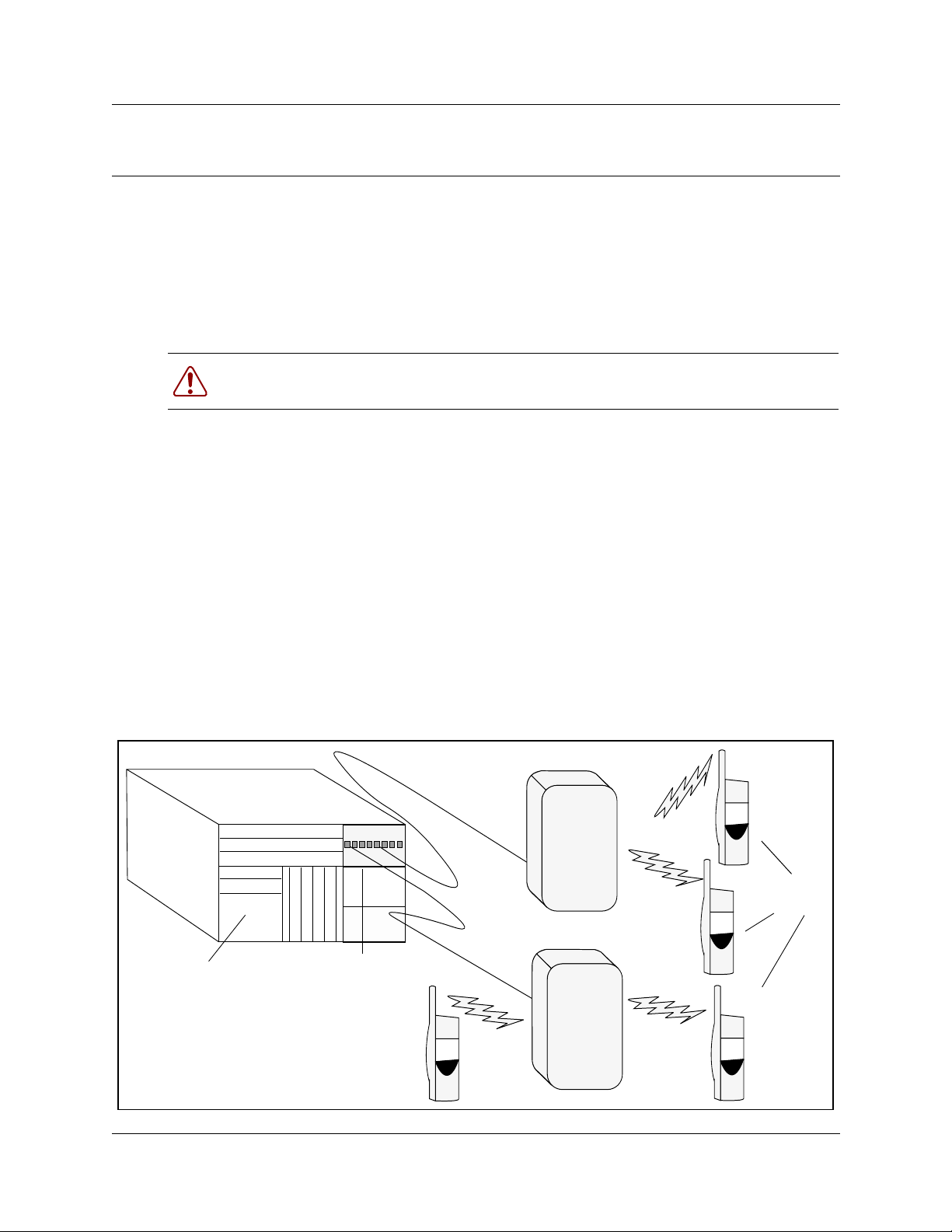
Figure 1 shows a gr aphic representation of the components of the system.
Table 1 on page 18 describes the thre e main hardware compo nents of the DECT system.
Figure 1 Integrated DECT service
Business
Communications
Manager
Media bay module
Handsets
Base stations
DECT Installation and Mai nte nan ce Guide
Page 18

18 Chapter 1 DECT System Overview and Requirements
Table 1 Hardware components of the DECT system (continued)
Component Function
DECT media bay module The module connects up to eight radio base stations. Use the B usiness
M6241 Radio base sta tion Each base station provide s radio cover a ge for a prescribed area. A group of
DECT cordless hands et
C4010 and C4020
DECT Features
The follo wi ng list describes some of the special features of the DECT system.
• The DECT module contains f our BRI ISDN-S lo ops. The Busi ness Communic ations Manager
assigns four loop records in the Unified Manager when the module is installed, based on the
DIP switch settings for the module.
Communications Manager Unified Manager application to initialize and
program the module.
Within the module, four BRI ISDN loops allow up to eight simultaneous
conversations. NOTE: Each Business Communications Manager system can
support one DECT module.
base stations mak e up a cell.
Each base station can support up to four simultaneous calls. The radio base
stations al so offer antenna diversity.
Use the site survey to determine the number of base stations required to
cover the area. Refer to “DECT Base Station Depl oyment Planning” on page
22.
Each handset provides the user with telephon y features remote fro m th e lan d
set.
This book contains only the registrati on ope rations for t he set . Refer to the
user manuals that came with your handset for op erational det ails.
Up to 32 handsets can be assigned to each DECT system.
• The cordless handsets are identified with DNs in the Unified Manager. They can be assigned
answer DNs to link them wi th stationary sets.
• The numbering plan and call rou ti ng defined in the Business Communications manager must
agree with the entries in the DECT interface.
Business Communications Manager Requirements
The DECT system only w orks wi th a Busines s Communica tions Manager syste m that has be en set
to a compatible regions. Confirm that this has been done before you attempt to install the system.
Regions are discussed in the Business Communications Manager 2.5 Programming Operations
Guide.
This book describes the handset dir ec tor y number (DN) system based on the default setup, where
the Start DN is 221 and the DN length is three digits. If your sys tem has a different DN structure,
use the tables provided to translate the DNs listed to match those of your system.
P0937236 02.1
Page 19
Chapter 1 DECT System Overview and Requirements 19
Examples of DN structures:
If your Start DN is 221 but you require a five-digit DN, the system auto ma tically creates a Start
DN of 22221 w hen you specify a five-digit DN at startup.
If your Start DN needs to start with a specific number, change the Start DN after you specify the
DN length at startup. For instance, if your Business Communications Manager is part of a CDP
(Coordinated Dialing Plan) network with fi ve-digit DNs, your system must have a unique fi rs t DN
digit, so you would specify the exact Start DN, in this case, something like 31111.
Checking the System Region
If you experience problems installing DECT on your system, check the region for which the
system is set.
Note: DECT systems can be installed in countries that can run the following region
profiles: UK, Australia, Sweden, Denmark, Holland, Norway, Italy, Germany, Spain,
Switzerland, France, Global, Hong Kong.
Refer to the Business Communications Manag er 2.5 Pro gramming Operations Guide
appendices for the chapter that lists all the regions.
Caution: You must select a region that reflects the geographical location of the
Business Communications Manager.
If you choose the wrong region, the Business Communications Manager system does
not communicate correctly with the Public Switched Telephone Network.
This procedure describes how to ensure that the Business Communications Manager is set to the
correct region for the DECT module.
1 Open the Unified Manager for your Business Communications Manager system.
2 On the navigation tree, click Diagnostics/MSC.
3 On the top menu, click on Configuration.
4 Click System startup.
5 Ensure that the Region box displays t he correct regio n. If not, select a region fr om the list.
Note: When you select a new region, the Template box is disabled. You must
restart the syste m befo re the templates for the selected region are a vailable.
DECT Installation and Maintenance Guide
Page 20

20 Chapter 1 DECT System Overview and Requirements
a Click OK to apply these changes.
Note: The system displays a warning that the system will restart and that the
default programming values will be restored.
b Click Cold Start to restart the Unified Manag er.
6 Continue with the DECT deployment.
P0937236 02.1
Page 21

Setup Process Overview
Figure 2 provides an overview of the actions required to successfully set up the DECT integrated
system:
Figure 2 Setup process for the DECT system
Chapter 1 DECT System Overview and Requirements 21
Plan the
deployment
Check
BCM system
settings
Install
media bay
module
Install the
radio base
stations
Connect
base stations
to module
Have a site plan and deployment strategy worked out. Refer to the M6261DECT
Deployment Tool Guide on the Business Communications Manager 2.5 CD.
Data repor t Site survey
Radio base stations location s Plan cells
Ensure that your Business Communications Manager has the correct Region
setting to allow DECT deployment.
Refer to “Checking the System Region” on page 19.
Refer to Chapter 2, “Installing the DECT Media Bay Module,” on page 31.
This procedure assumes the Business Communications Manager i s ins tal led
and commissioned.
Refer to Chapter 4, “Installing the DECT Base Station,” on page 49.
Check the site map for obstacles and possible sources of interference to the
radio signal or data link.
The first radio base station must be within 800 m of the DECT media bay
module. Attach the components using 0.6 mm cable.
Program
the DECT
module
Subscribe
cordless
handsets
Refer to Chapter 6, “Programming DECT Module Defaults,” on page 69, Chapter
7, “Programming Numbering Plans and Base Stations,” on page 75, and Chapter
8, “Programming DECT Handset Records,” on page 85.
Many of the module settings are prec onfigured. These chap ter s describe the
settings that are requir ed for the module to work corr ectly.
Refer to Chapter 5, “Subscribing DECT Cordless Handsets,” on page 57.
When the system and module DNs have been assigned, sub scribe each
handset. Test the handsets with each base station.
DECT Installation and Maintenance Guide
Page 22

22 Chapter 1 DECT System Overview and Requirements
DECT Base Station Deployment Planning
The DECT base stations must be deployed to provide full site cov erage with the maximum traffic
capacity, using the minimum number of base stations.
There are two t as ks involved in arranging this:
• Surveying the site: the site survey involves gathering info rmation to determine customer
requirements and the number of cells needed to support the traf fic.
• Planning deployme nt: deployment plans est abl ish the best locati ons for the radio base st ations.
Site surveying and deployment planning are complex tasks, undertaken only by trained personnel.
Refer to the M6261DECT Deployment Tool and site planning guide for detailed Site planning and
deployment.
DECT Radio Base Station
The Business Communications Manager can support one DECT media bay module.
A cable attached to a n RJ45 connect or in the f ace of th e DECT module connec ts to the ba se station
RJ45 connector. This supplies the data and power.
The base station comes with two internal antennas to provide signal diversity. Some types of
external an tennas can be substituted, depending on site requirement s.
Table 2 describes the function of the parts of the base station.
Table 2 Parts of the DECT radio base station configurations
Part Description of function
Base stations The area covered by the base station depends on the radio range. Base stations
Cables The cable includes two telephone pairs .
Connectors The base station uses a female RJ45 to connect to the cable.
Switches There are two configuration switches: the CA1 and the S202.
manage the links with the cordless handsets within that r an ge.
One transmits the signal.
One receives the signal.
• The CA1 has two switches, labelled 1/2 and 3/4.
Set 1/2 to On to enable the adaptation resistor for the synchronization pair.
Set 3/4 to On to enable base station Reset.
Set 3/4 to Off to run Reset by S0 interface level 1.
• The S202 has two switches, labelled 1/2 and 3/4.
Set 1/2 and 3/4 to On to enable the 100 ohm adaptation resistors for the S0
pairs.
Refer to Figure 3 on page 23.
P0937236 02.1
Page 23
Chapter 1 DECT System Overview and Requirements 23
Table 2 Parts of the DECT radio base station configurations (continued)
Part Description of function
Figure 3 Base station switches
Jack
Adaptation RNIS
External Antennas
Three kinds of external antennas can be added:
• The MA431X23 is omnidirectional wit h an e xtension cord.
• The MA431X24 is omnidirectional wit h an e xtension cord.
• The MA821X12 is bidirectional wit h a 50- cm cable.
The HT6176A is an adapter for outdoor antennas.
Warning: Do not add any more cables to the MA821X12, or the gai n a nd r eceptivity wil l
suffer. Place this antenna as close to the base station as possible.
RJ45
4
3
S202
On
Adaptation synchron iz er
2
1
4
3
On
Reset
2
1
CA1
The MA431X23 and X24 antennas can be installed further from the base station. Ensure that the
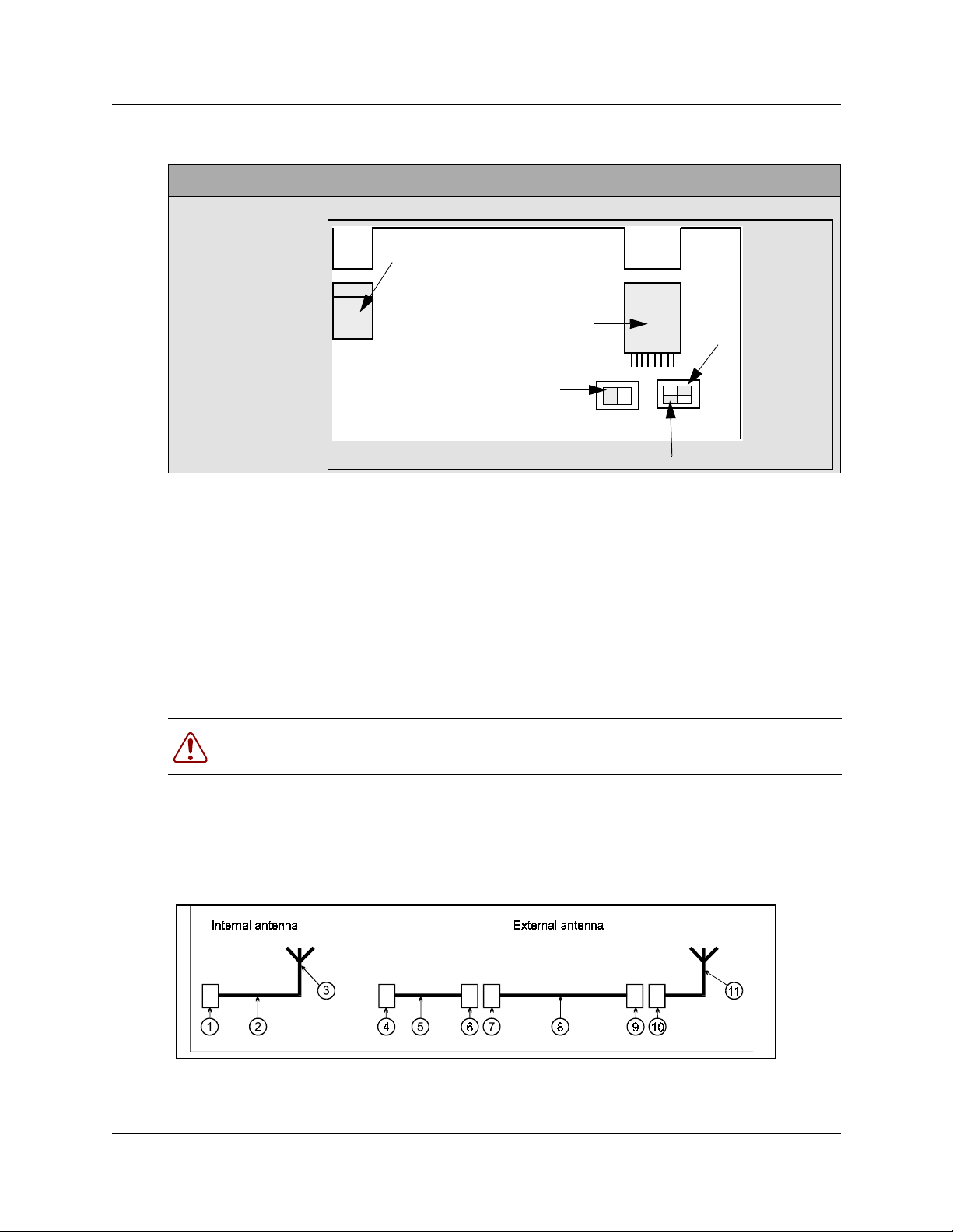
coaxial cables linking the antennas with the base stations provides low attenuation. Figure 4
illustrates two configurations :
Figure 4 Antenna configuration s
• The internal ant enna incorporates an MMS connector (1), one coax ial cable KX21 (2) and the
radiating element (3). The antenna gain is 2 dBi.
DECT Installation and Maintenance Guide
Page 24
24 Chapter 1 DECT System Overview and Requirements
• The external antenna is connected via a cord (4-5-6) which incorporates an MMS male
connector (4), coaxial cable KX21 (5) and a TNC female connector (6). The manufacturer
specifies loss es of less tha n the guaran teed dB v a lue. Lo sses a re ac tuall y o f the order of 0.7 dB
at 2 GHz.
The extension cor d conveying the signal to the antenna incorporates a TNC male connector
(7), low loss coaxial RG58cu cable (8) and N male connecto r (9) . The antenna (11) is secured
to the extension cord using N female connector (10).
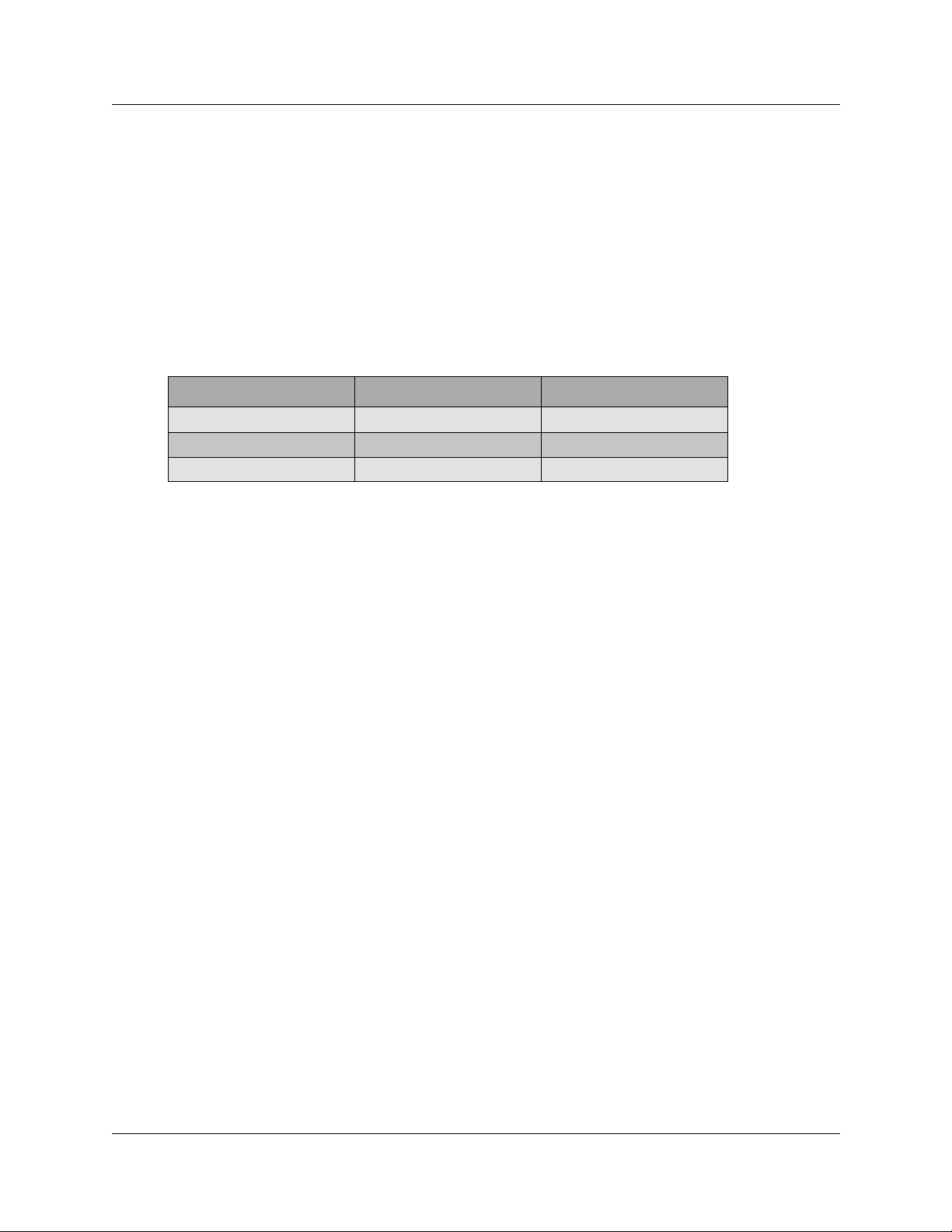
The losses generated by this extension cord are summarized in Table 3:
Table 3 Generated losses with extension cord added
Element Losses at Frequency Estimated losses
RG58cu 0.65dB/m at 2GHz
TNC 0.2 dB at 9GHz 0.1 dB
N 0.15 dB at 10GHz 0.1 dB
• The maximum length of the extension cord is 2.8 meters.
• The MA432X23 external antenna with an extension cord performs approximately in the sa me
way as an internal antenna, except for the polarization diversity.
• The MA432X24 provides a 2 dB gain compared to the internal antenna.
P0937236 02.1
Page 25
Chapter 1 DECT System Overview and Requirements 25
Specifications for DECT Radio Base Stations
This section describes the radio base station specifications.
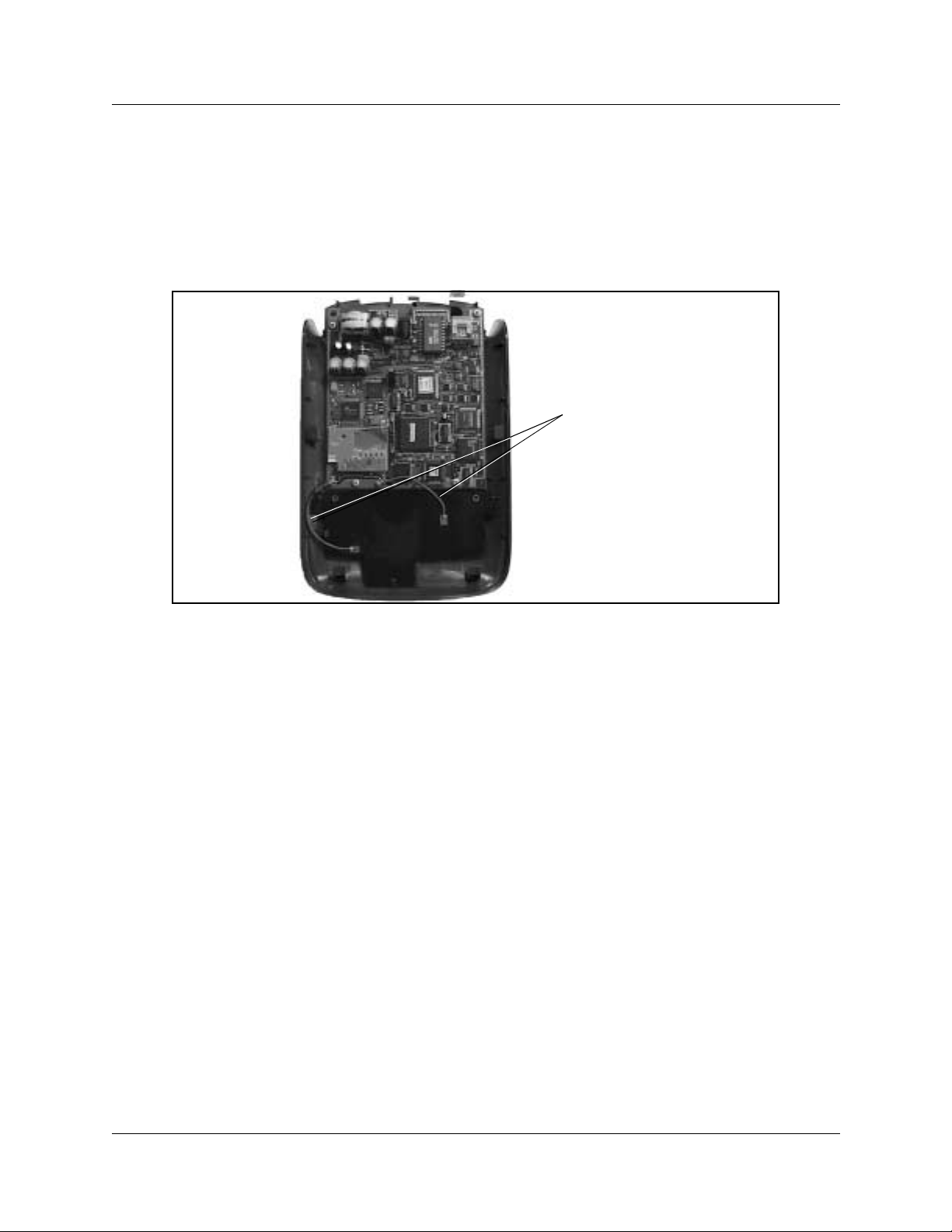
Figure 5 shows the base station with the top cover removed.
Figure 5 Inside the DECT radio base station
Internal antennas
The follo wi ng spe cifications appl y to DECT radio base stations:
• frequency band: 1880 -1900 MHz
• number of radio channels: 8
• transmission power: 250 mw (peak)/10 mw (average)
• instantaneous throughput of the channel: 1152 Kb/s
• signaling channel throughput (D channel
between the module and the base station): 16 Kb/s.
• antenna type: omni-directional [one-way] or
directional integrated or ext ernal
antennas
• coverage range: from 10 to 30 metres (office
environment), up to 300 metres (open
air)
• radio base station operating temperature: +5 to +45× C
• number of simultaneous calls per radio base station: two or four
• base station synchronization: yes
DECT Installation and Maintenance Guide
Page 26

26 Chapter 1 DECT System Overview and Requirements
Base Station Notes:
Here are some general-information notes about the base station:
• Do not install more than two overlapping radio base stations per cell.
• Do not apply any new paint scheme to the plastic shell without written approval from Nortel
Networks.
• Use the Unified Manager to perform resets o f the base station .
• Signal processing functions for the four- channel radio base station are ported to t he MBM. In
this case, the inte rface transports four 32 Kb/s ADPCM coded communications as well as 16
Kb/s signa ling channel.
Climatic Conditions
The DECT base station can tolerate the following conditions:
Operational:
• Temperature: 5 to 45 degrees C.
- 20 to +60 with a special cabinet
• Relative humidity: 10 to 80 per cent, not condensing.
Storage:
• Temperature range: - 10 to 60 degrees C.
• Relative humidity range: 10 to 90 per cent, not condensing.
Power Supply
The ISDN interface in the DECT media bay module enables the base stations to be powered
through the cable conn ect ion between the DECT and the b ase st ation. The remote powe r s upply is
limited to 100 mA on the DECT interface, which corr esponds to an available power of 4 W at 48V.
The radio base station can also be powered using a local a.c./d.c. mains power supply unit,
PN 840 B. Use a local supply unit for no more than two radio base stations in any given cell.
Description of the Connection
DECT base stations connect to DECT media bay modules using a cable containing two twisted
pairs. This cable connects to RJ45 connectors on the components. The co nnection at the DECT
position corresponds to an equipment number on the two cards on the DECT module that control
the base station interaction. If you assign specific base stations to equipment numbers, you must
ensure that base station is connected to the appropriate RJ45 jack on the DECT module.
P0937236 02.1
Page 27

DECT Cordless Handsets
Check for small metal o bje cts in the DECT Handse t earp ie ce/mout hpiece before using t he
handset.
Do not store or locate flammable liquids, g a ses, or explosi ve materials in the same
compartment or vicinity as the cordless handset, its parts or accessories.
Chapter 1 DECT System Overview and Requirements 27
This section describes the features provided by the
handsets were developed to work with DECT systems.
Other cordless hands ets ca n be us ed with th e DECT syst em. The s ystem f eatur es a vailable t o other
handsets depends on how the handset is configured, and how compatible it is with the signals
transmitted from the DECT module. As well, some features such as call display also require the
proper line configurations at both the local and telco end of the line.
Site Configurations
Nortel Networks provi des one PARI number on the DECT module that all the base stations share.
Access is authorized by matchin g the PARI number and the PARK number registered in the Other
multi-site configurations.
DECT Call Paths
The DECT module provides a telephony path separate from the Business Communication
Manager system. This means there are three possible paths for a call to take.
• A DECT handset-to-handse t call is rout ed from t he call ing handset, throu gh the DECT mod ule
C8, into th e receiving hand set.
C4010 and C4020
cordless handsets. These
• A DECT handset-to-Business Communications Manag er set call is routed from the calling
handset, into the C8, and into the Business Communications Manager. The Business
Communications Manager then routes the call through the appropri ate station module to the
receiving set.
• A DECT handset-to-external call is routed from the calling handset, into the C8, and into the
Business Communication s Manager. The Business Communications Manager then routes the
call through the appropriate trunk module out to the public network. This is the same route a
call from a DECT handset to a set on a private network wou ld use. The difference is that the
user enters a different destination code.
• If a DECT handset transfers a cal l, the DECT C8 processes the transfer and crea tes a new call
destination. The call remains routed through the C8, even though the DECT handset is no
longer in volved in the call.
DECT Installation and Maintenance Guide
Page 28
28 Chapter 1 DECT System Overview and Requirements
DECT Programming Overview
Here are some important points about using DECT on your Busines s Communi ca tio ns Manager.
• The Business Communications Manager must be configured with a region setting that
provides DECT supp ort.
Note:
Australia, Denmark, France, Germany, Global, Holland, Hong Kong, Italy, Norway, Spain,
Sweden, Switz e rland, Taiwan, United King dom
• The system default pas sword is set to
V alid DECT region settings :
insta
. You can delete or change this password to suit
your needs.
• Default language is Engli sh.
• Disable the base stations before a firmware upgrade. Put the base stations back in service in
sequence.
• To subscribe handsets, the base stations must be set to accept handset recording.
• The handset DN must also be set into recording mode before the handset can be subscribed.
• The system uses data links.
• Within the DECT interface, numbers enclos ed in ( ) indicate le n gth of parameters.
Note: Refer to the Business Communications Manager 2.5 Programming Operations
Guide to configure handset features for ea ch han dset DN.
DECT Interface Commands
Table 4 shows the main commands that are needed to navigate the DECT interface.
Table 4 DECT interface commands
Command Explanation
10 (no return) Sets the initial interface to VT100. This command is not
Ctrl U Goes to main menu.
Ctrl J Moves up one lev e l of menus.
space bar Toggles between items within screens.
Esc (alpha commands) ESC M = more
Del Deletes ite m backwards .
Note: Data changes take effect immediately! There is no REDO option.
P0937236 02.1
always necessar y.
A list displays at the bottom of each screen.
Page 29
Chapter 1 DECT System Overview and Requirements 29
Numbering plan syntax
Table 5 explains how the syntax for the numbering pl an works:
Table 5 Numbering plan syntax
Number Plan width Entry Means
(2) 1-2 10 to 29
(3) 12-3 120 to 139
(5) 1623-4 16230 to 16249
(5) 1-2 10000 to 29999
DECT Installation and Maintenance Guide
Page 30

30 Chapter 1 DECT System Overview and Requirements
P0937236 02.1
Page 31

Chapter 2
Installing the DECT Media Bay Module
This section describes how t o install the DECT media bay module in the Business
Communications Manager. Figure 6 shows an overview of the process.
Figure 6 Process for installing the DECT module
Site
planning is
complete
31
Base stations ar e
installed
Note the PARI number
on the side of the
module
Set the DIP switches
on the back of the
DECT module
Prepare system for
shutdown
Shut down the system
Remove the front bezel
Remove the media
bay cover
Install the DECT
module
Restore system to
operation
Go to Chapter 3,
“Configuring the Mod ule,”
on page 37 to perform the
module identification and
initialization.
DECT Installation and Mai nte nan ce Guide
Page 32

32 Chapter 2 Installing the DECT Media Bay Module
Setting the DIP Switches
This procedure describes how to set the DIP switches for the DECT media bay module.
Ensure that you wear equ ipmen t to p roperl y groun d yours elf whi le handl ing an y of
the electr oni c parts to this system.
1 Take the media bay module from its box.
2 Inspect the module for damage.
3 Make a note of the PARI number, which is located on the side of the module.
4 Determine which DS30 channel (bus) number to use for th e module.
Note: Remember that the channel you choose cannot conflict with a location already
assigned to an existing media bay module.
Use Bus 6 or 7 if they are available.
5 Set the DIP switches, located on the back of the DECT module to the DS30 channel number.
Set the offset to 0 (on).
• Figure 7 shows the location of the DIP switches on the DECT module.
Figure 7 Locating the DECT media bay module dip switches
Off
6 5 4 3 2 1
On
P0937236 02.1
Page 33

Chapter 2 Installing the DECT Media Bay Module 33
• Table 6 shows the switch settings for each module number. The offset number is always 0.
Table 6 DECT switch settings
Select
DS30
channel
2 0
3 0
4 0
5 0
6 0
***7 0
*If you need more DNs, us e DNs in the portable DNs , starting at 565. Ensure no other de vic es are assig ned
to these DNs bef ore you use them.
**Note: The e xtension s listed ar e based on a three-digit D N with a Start DN of 221. If y our syste m has long er
DNs or a diff eren t Sta rt DN, enter the range in the blank column.
***If your syst em ha s a 3/5 DS 30 c hanne l spl it, ch annel 7 is not a vailable to m edia b a y m odul es . Refer to the
Programming Operations Guide for further information on this feature.
Select
offset
on on on on on on
on on on on on
on on on on on
on on on on
on on on on on
on on on on
Set the switches
123456
off
off
off off
off
off off
Use these
DNs on nre
2.5 systems
597-624* 501-532*
597-624* 501-532*
597-624* 501-532*
597-624* 501-532*
597-624* 501-532*
597-624* 501-532*
Use these
DNs on
updated 2.0
system
**Customized DN
range
Note: If you replace a module, set the DIP switches for the new module to exactly the
same settings as the rem oved m o dule.
TIP: Numbering conventions:
This document assumes three-digi t DNs, starting with a Start DN of 221. If your system
has a differe nt numbering pla n, adjus t th e numberi ng accor dingl y. If you follow a differ ent
numbering plan, ensure that you update all the DN settings described in Chapter 8,
“Programming DECT Handset Records,” on page 85.
Use Table 7 to note the settings you chose.
Table 7 Module settngs
Module PARI number:
DS30 channel:
DIP switch settings:
Notes:
DECT Installation and Maintenance Guide
Page 34

34 Chapter 2 Installing the DECT Media Bay Module
Installing the DEC Module
After you have set the DIP switches, you can install the modules. You need to shut down the
system to install the module, therefore, choose a period when the Business Communications
Manager is not busy.
Remember to warn users that the system wi ll be down for a short period.
1 Ensure the Business Communications Manager base unit is properly shut down.
a From the Unified Manage r applic ati on, click System, then go to the Logoff menu and
click Shutdown.
For detailed shutdown information, refer to the Business Communications Manager 2.5
Pro gramming and Operat ion s Guide.
b Disconnect all the cables from the front of the Business Communications Manager base
unit and expan sion unit, if there is one.
c Disconnect the base unit and expansion unit power cords from the a.c. outlet.
Danger: Failure to follow these steps can result in damage to the system or the
module.
d Remove the fron t bez el fr om the f ron t of th e base unit o r e xpans ion unit wh ere you plan t o
install the DECT module.
2 Remove the bla nk cover from the module bay.
To remove the bay cove r, pull the tab beside the module bay. This pushes the cover forward.
Figure 8 shows the base unit and expansion unit front bezels.
Figure 8 Release tabs for the module bays
Business Communications Manager base unit
Media bay coverplate
and module release
tabs
Business Communications
Manager expansion unit
P0937236 02.1
Page 35

Chapter 2 Installing the DECT Media Bay Module 35
3 Insert the module into the open bay and push until the module clicks into the backplate.
Note: The module protrudes slightl y. After the front bezel is replaced, the face of
the module sits flush with the front of the unit.
4 Replace the front bezel on the Business Communications Manager or the expansion unit.
Figure 9 shows the base unit and expansion unit with the front bezels replaced.
Figure 9 Front bezels replaced on units
Business Communications Manager base unit
Bezels replaced on units
Business Communications
Manager expansion unit
Restoring the system
After the module is installed, restore the Business Communications Manag er operations. Then
connect the base station cables to the module.
1 Inspect the system to ensure all components are in place.
2 Reconnect the a.c. power cords for the Business Communications Manager base unit and the
expansion uni t, if there is one.
3 Reconnect all the connections to the front of the units.
Warning: Failure to follow these steps can damage the system or the module.
4 Monitor the LE Ds on the front of the base unit t o ensure the system reboots pr operly. Refer to
Figure 10. This process takes a few minutes.
— Power (working status)
— Status (har dware status )
— Run (CPU of the DECT C8) (blinks when stable)
— 48 V for the base station jacks
DECT Installation and Maintenance Guide
Page 36

36 Chapter 2 Installing the DECT Media Bay Module
Figure 10 Locating the LEDs on the DECT module face
Power LED
Status LED
Run
Base station power
5 When the power and status LEDs on the module are solid green, you are ready to continue
with the module configuration. Refer to Chapter 3, “Configuring the Module,” on page 37,
If the lights are off or are blinking, refer to “Monitoring the DECT Module LEDs” on page
106 for troubleshooting information.
P0937236 02.1
Page 37

Chapter 3
Configuring the Module
There are some preli minar y steps that you must do wi thin the Business Communic ations Manager
Unified Manage r appl ication before you run the wizard that configures the DECT module. This
chapter describes how to ensure that the Business Communications Manager system sees the
DECT module. It also describes how to find and manage the DNs designated for DECT handsets.
When the Unified Manager set tings ha v e been done, you ca n run the DECT Conf igu rati on wizard.
This wizard configures the DECT module. It also turns on one of the base station ports to allow
handset subscription.
Handset subscription (mobile recording) can also be turned on and off using the DECT Mobile
Recording (handset subscription) wizard, which is also described in this chapter.
Figure 11 describes the steps you need to take to identify and configure the DECT module.
Figure 11 Process for identifying and configuring the DECT module
37
Identify the
DECT
module
In Unified
Manager,
choose handse t
DNs
Run the
DECT
Configuration
wizard
Set
module
time synch
Connect
the base
stations to
the module
Ensure the Business Communications Manager recognizes the DECT
module.
These DNs must match the DNs you enter on the DECT interface.
Use the default DNs, unless your system requires a different numbering
scheme.
Refer to “Setting up the Handsets” on page 40.
The DECT Configuration wizard sets up the DECT module, using the
default DNs you specified. Refer to “DECT Configuration Wizard” on
page 42.
After you run the Wizard, ensure that the module is time synched with
After you run the Wizard, ensure tha t the modul e is time synch ed with
the Business Communications Manager.
the Business Communications Manager.
Refer to “Setting Up the Module Time Synch” on page 45.
Refer to “Setting Up the Module Time Synch” on page 45.
After the configuration wizard is complete, connect the base stations to
the module and subscri be the hand se ts.
Refer to “Connecting the Base Station to the System” on page 52, and
Chapter 5, “Subscr ib ing DECT Cordless Handset s,” on page 57.
DECT Installation and Mai nte nan ce Guide
Page 38

38 Chapter 3 Configuring the Module
Confirming the DECT Module
After the DECT module has been installed and the system has rebooted, you must identify the
module to the Business Communicati ons Manager system.
Use this procedure to ensure the system recognizes the module type.
1 On the navigation tree, click the key beside Resources.
2 Click on Media Bay Modules.
3 Click on the Bus number for the DECT module.
4 Ensure that Programmed Bus Type is s et to Trunk Module.
5 Click the key beside Modules on Bus.
6 Click on Module 1.
7 Ensure that Module Type is set to DECT.
8 If you made changes, do the following, otherwise continue with step 9:
a Click on the Bus number again.
b Under Configuration, choose Disable.
c On the message box, click OK.
d Under Configuration, choose Enable.
When the module is enabled, the State field reads: equi pped.
9 At the bottom of the Resources list, click on the DECT heading,
10 Confirm the module name, or sel ect the correct module.
Note: If the module does not immediately appear on the list, wait a few minutes and try
again.
Note: If the system does not recogni ze the DECT module, the DECT heading under
Resources will not appear.
P0937236 02.1
Page 39

Chapter 3 Configuring the Module 39
Checking the Unified Manager Handset DNs
The DECT handset is conside r ed an ISDN S device. Assign the handset to DNs within the default
ISDN and DECT range. Ensure that you do not assign handset DNs that have already been
assigned to other ISDN devices.
Note: Default DECT module DNs:
• New 2.5 Business Communications Manager: 597-624
• Upgraded 2.0 Business Communications Manager: 501-532
These defaults assume a system with a three-digit DN structure , and a Start DN of 221. If
your system is different, use these numbers as gui delines to find the defaults to your
system.
Note: If you need more DNs than are available in the default range, use the
NA Portab le DNs. Ensure these DNs are a vailable before assigning them.
1 Open the Unified Man ager.
2 From the menu, click BCM/Services/Telephony Services/System DNs/All ISDN/DECT
DNs.
3 Click on the DN number you want to assign to the handset.
4 Under the DN number, click General.
5 When the Genera l scre en appears, ensure that the DN Type displays ISDN and DECT.
6 Repeat for all handset DNs.
7 Refer to “Setting up the Handsets” on page 40 for informatio n about set ti ng up the DN
records.
8 When the records are set up, run the DECT Configuration wizard. Refer to “DECT
Configuration Wizard” on page 42.
9 The confi guration wizard also set s up the system to start subscribing handsets.
10 To turn off handset subscription (mobile recording), run the DECT Mobile Recording
(Handset Subscript ion) wizard. Refer to “DECT Mobil e Recording (Handset Subscription)
wizard” on page 47.
11 To check the DNs against the DECT module DNs, refer to “Listing Mobiles” on page 90.
DECT Installation and Maintenance Guide
Page 40

40 Chapter 3 Configuring the Module
Setting up the Handsets
How you want to use the DECT handset will determine how you set up the handset DN record.
This section describes t he wa ys the handsets can be used.
Detailed configuration information is contained in the Business Communi cations Manager 2.5
Pro gramming Operat ions Guide.
The DECT cordless handsets e ither ca n be set to r ing in ta ndem with a st ationary set, or conf i gured
to act as stand-alone sets. As well, the handsets can be configured as target lines to accept direct
inward dial (DID ) calls.
This following sections explain the Unified Manager settings required for each type of scenario.
Stand-alone Handset
A stand-alone set can be configured to only receive calls, or to both send and receive calls
internally or externally.
Internal Calls
The DECT interface comes with a set of default DNs. After the handsets are registered to these
DNs, and the DNs are activated, the handsets can be used to make calls between sets.
After the DECT handset DNs are added to the Unified Mana ger, the handsets can be used to make
and receive calls internal to the Unified Manager system.
External Calls
The handset can be configured to have full send and receive capability to the public switched
telephone network (PSTN), or, by using a target line, can be configured to receive calls only.
Assigning routes or lines
The Unified Manager automatically assigns all DNs with the default Pool A. This automatically
allows call s thr oug h this l ine p ool. Thi s li ne pool can be deleted, and other po ols added , depend ing
on your requirements.
1 Open the Unified Man ager.
2 On the navigation tree, click BCM/Servi ces/Telephony Se rvices/System DNs/
All ISDN DECT DNs/DN ##, where DN is the DN of the DECT handset.
3 Ensure you have a line pool set up that you want to use.
4 Click Line Pool Access, and click the Add button at the top of the column.
P0937236 02.1
Page 41

Chapter 3 Configuring the Module 41
5 Click the line pool you want the handset to use to make and receive calls.
6 Repeat, as necessary.
Assigning target lines
If you want the handset to receive calls but not to be able to send calls, set up a target line for the
handset.
Note: If you do not want the user to be able to dial out at all, ensure that no other lines or
line pools are assigned to the set.
1 Open the Unified Man ager.
2 On the navigation tree, click BCM/Servi ce s/Telephony Servic e s/Lines/Target Lines.
3 Click a target line number heading that is not already assigned.
4 Click on Trunk/Line data.
5 Click on Received Number.
6 Enter the handset DN number.
7 On the navigation tree, click BCM/Servi ces/Telephony Se rvices/System DNs/
All ISDN DECT DNs/DN <handset DN>.
8 Click on Line Access/ Line Assignment.
9 Click the Add button at the top of the navigation tree.
10 Add the line number of the target line in Line field.
11 Click Save.
12 Click on the Line <target line number> heading.
13 Ensure Appearance is set to Appr. & Ring.
Assigning Handsets to Fixed Telephone DNs
You can also associate the handsets with fixed sets. With this feature, the handset rings whenever
the fixed set rings .
1 Open the Unified Man ager.
2 On the navigation tree, click BCM/Servi ces/Telephony Se rvices/System DNs/
All ISDN DECT DNs//DN ##, where DN ## is the DN you want to assign to the handset.
3 Click Answer DNs.
4 Enter the DN number for the fixed set to be associated with the handset.
5 Press <Tab> to update the record.
6 Repeat this process for all handsets you want to assign.
DECT Installation and Maintenance Guide
Page 42

42 Chapter 3 Configuring the Module
Handset Feature Programming
The call features available to DECT handsets are described in “Handset System Features” on page
64. Programming for these features is the same as for other Business Communications Manager
telephones with these features. Refer to the Business Communications Manager 2.5 Programming
Operations Guide for instru ction s. Refer to the handse t user manual for instruct ions on how to use
the features.
About the DECT Wizards
These wizards will lead you through the necessary procedures to configure your DECT module
and set up the module for subscribing the handsets.
If you need to change an y of t hese se ttin gs a fter the wiza rds ar e run, r efer to the speci f ic pr ocedur e
described in the following chap ters.
DECT Configuration Wizard
Use this wizard to pe rf orm the i nitial configuration of a DECT module and to set up a base stat ion
to allow handsets to be subscribed to the system.
Note: At this point you have not yet connected the base station cables to the module.
The wizard collects current information about the DECT settings from the Business
Communications Manager, and sends them to the DECT module. None of this information
displays on the screen, except for the ISDN or DECT DNs.
Warning: Use this wizard ONLY for initial configuration, as it wipes out any previous
DECT module information.
Refer to “Using the Wizards” on page 44 for the steps about how to run the wizard.
P0937236 02.1
Page 43

Chapter 3 Configuring the Module 43
Before You Start
The follo wi ng conditions are required before you run the wizard.
• The telephony (DNs and line access), routing information, and any line pool access coding
must be configured on the Business Communications Manager.
Note: Any changes made after the wizard is run will not be reflected on the DECT
module. This is an instance where you would need to go directly into the module settings
and check or adjust the settings.
• The DECT module must have the factory default settings applied to it. If these have been
changed in any way since the module was installed, you can reset the module through the
Wizard.
• You must ensure that the Business Communications Manager recognizes the DECT module.
Refer to “Confirming the DECT Module” on page 38.
You need to know the following information before you run this wizard:
• Do you want to reset the DECT module to the factory
default sett ings?
What is the PARI value that you copied off the side of the
No Yes
(PARI value)
DECT module before it was installed?
• How do you want to identify the DECT module? (Install Name)
• Which base station do you want to enable to allow
terminal sub s cription?
Refer to “Identifying Base Stations” on page 87 for more
(base station)
6-0 6-1 6-2 6-3
7-0 7-1 7-2 7-3
information about numbering.
• How many handsets will you be subscribing?
Which DNs are assigned to these handset s in the Unified
Manager?
(DN number)
Yes (enable)
No (no handset assigned)
Note: The Busin ess Commun icati ons Manage r pro vid es up to 28 ISDN or DECT DNs. If
you require more handsets, or if some of the DNs are already used for other equipment,
you can change the DNs in the NA Portable range to ISDN or DECT.
This must be done b efore you run the Wizard, as the wizard only recognizes DNs with the
ISDN or DECT label. Refer to “Checking the Unified Manag er Handset DNs” on pag e 39
for more information about de f ault DNs.
DECT Installation and Maintenance Guide
Page 44

44 Chapter 3 Configuring the Module
Using the Wizards
Wizards are accessed through th e Wizard button that appears on the first page of the Unified
Manager.
Warning: Ensure there is no one else using the tables the wizard will be using.
1 On the first page of the Unified Manager, click the Wizards button.
A new page appears, displaying all the types of wizards that can be used for the Unified
Manager.
2 Click on the DECT Wizard button for the task you want to perform.
Note: If the system does not recognize the DECT module, these buttons do not appear.
Refer to “Before You Start” on page 43.
3 Enter the require d information in to the fields on the wizards.
4 Click the Apply button on the screen to invoke the wizard.
Filling Out the DECT Configuration Wizard
The DECT Configuration wizard has three pages.
1 On the first page, you specify the DECT module information and the base station that you
want to turn on to allow handset subscription. If you choose None, then all base stations are
turned off.
2 The second page allows you to determine which DNs will be assigned to handsets. Scroll to
the bottom of the page to find the Next button to move to the third page.
3 The third page provides a summary of the entries, with a list of the DNs you selected.
The Apply button is on this page.
P0937236 02.1
Page 45

Chapter 3 Configuring the Module 45
Setting Up the Module Time Synch
After you run the Configuration Wizard, you need to ensure that the module time is synchronized
with the Business Communications Ma nager . Since the module time can drift out of synch, you
can use this BRU tool to set up a schedule for daily time synchronization.
The time can also become unsynchronized if you perform firmware uploads. As well, if you
change the password, you must re-establish the time synch schedule.
Follo w these steps to set up a time synch schedule:
1 Do the following to check that the correct DECT module is selected:
a On the navigation tree, click the Resources key.
b Click on DECT.
c Confirm the module name, or select the correct modul e.
2 At the top of the navigation tree, click on BCM.
3 Under Tools, click on BRU.
4 At the prompt, enter the user name and password for the supervisor account.
A new Internet Explorer (IE) window appears. Refer to Figure 12.
Figure 12 Choosing the BRU mode
5 Under Load XML File, choose DECTTimeSync.xml.
6 Under Select the Mo de, choose Synchronize.
After you choose Synchronize, additional selection boxes appear. Refer to Figure 13.
Figure 13 Choosing the components and timing
7 In the Select Components box, select DECT MBM Time.
DECT Installation and Maintenance Guide
Page 46

46 Chapter 3 Configuring the Module
8 In the Scheduled Process box, under Frequency, select Daily.
The current date appears in the Date boxes. Refer to Figure 14.
Figure 14 Setting the scheduled date an d time
9 Use the arro ws to select a time when you want the operation to be performed each da y.
Warning: Ensure this time you choose occurs during a low-activity period and
when no other DECT administrative processes are running, such as scheduled
backups.
10 Click the Execute button. The Password for DECTOAM Backup dialog box appears.
11 Enter the DECT administrator password. The default password on a new system is
insta
12 Click the Submit button.
When the schedule is created, a message appears at the bottom of the BRU window in the
status area.
Note: If you change the DECT Administrator password after this schedule is set, you
must delete the scheduled task. To delete the task, click the Schedule
link on the BRU
window to displ ay the tas k, then click the Delete button.
After the task is deleted, follow the above steps to set it again using the new password.
.
P0937236 02.1
Page 47

Chapter 3 Configuring the Module 47
DECT Mobile Recording (Handset Subscription) wizard
Use this wizard to turn on a base station to allow handset subscription, which is described in
Chapter 5, “Subscribing DECT Cordless Handsets,” on page 57.
You can also use this wizard to turn off mobile recording when you have completed the handset
subscriptions.
Note: When one base station is set to on, then all other base stations are off.
Do not use this wizard until all other DECT module par am et er s are set .
Read “Before You Start” on page 47, and then refer to “Using the Wizards” on page 44 for the
steps about running the wizard.
Before You Start
You need to know the following information before you run this wizard:
• What is the system password?
Default:
insta
• Which base station do you want to enable to allow terminal
subscription?
Refer to “Identifying Base Stations” on page 87 for more information
(Password)
(base station)
6-0 6-1 6-2 6-3
7-0 7-1 7-2 7-3
about numbering.
Note: Pick the base station that is in the most convenient proximity
to where the handsets will be subscribed.
Filling Out the Mobile Recording (Handset Subscription) Wizard
The DECT Mobile Recording (Handset Subs cription) wizard has two page s.
1 On the fir st page you enter the syst em pas sw o r d, if there is one, and choose the base station to
set for mobile recor ding (handset subscription).
2 The second page d is plays a summary of your entries and presents the Apply button.
Turning off mobile recording
When you are finished subscribing the handsets, run the wizard again and select None in the
Mobile Recording (Handset Subscription f ie ld) to turn mobile recording off.
DECT Installation and Maintenance Guide
Page 48

48 Chapter 3 Configuring the Module
P0937236 02.1
Page 49

Chapter 4
Installing the DECT Base Station
This chapter describ es how to install t he DECT base s tati on acco rding t o the de plo yment si te pla n.
Ensure that you have a complete deployment and site plan before you start.
Installing Base Station Hardware
This section describes how to install the base station hardware.
Use only qualified personnel to install or maintain the DECT radio base stations.
Special Considerations
There are a number of considerations you need to take into account before you install a base
station:
49
• Base stations must be positioned exactly where indicated on the site mapping plan. Any
changes can affect transmission and reception.
• Avoid installing base stations on metall ic surfaces or load - b ear ing walls made of reinforc ed
concrete. If a metallic surface cannot be avoided, use a 50- to 80-cm extension bracket. Metal
can impair transmission and reception.
• Place the base statio ns less than four meters from the grou nd. This m a kes it easier to maintain
the base station and ensures correct radio coverage. Do not place stations lower than two
meters.
• Do not inst all the base st ation behind obstructi ons , such as false ceilin gs.
• Always hang the base station in a vertical position.
• Leave at least 30 to 50 cm between co-located base stations.
• Install outdoors base stations in sealed cabinets.
• Leak-tight cabinets (reference DECT052) let you install DECT radio base stations outdoors
without an external antenna. A mounting kit (referenc e DECT055) lets you secur e the lea k
tight cabinet to a pole.
Note: Two base stations positioned side by side increase the channel capacity
from four to eight possible simultaneous calls. Tandem base stations must be
placed exactly 85 cm fr om each other. They also must be part of the same cell and
trunk gr oup.
• If you are using external an tennas, refer to “Base Station Antennas” on page 54.
DECT Installation and Mai nte nan ce Guide
Page 50

50 Chapter 4 Installi n g the D ECT Base Stati on
Installing the Base Station on the Wa ll
Follow these steps to properly attach the base station to the wall.
1 Locate the base stations according to the site survey and deployment information.
Position the base st at ions at the ex act point determined by the deployment sur v ey. Moving the
base station by one or two meters can harm transmission and reception.
Ground yourself with an antistat ic grounding strap bef ore performing
procedures inside the base station housing
2 Slide the cover of the base station upwards, then pull it away from the back panel. Figure 15
shows the base station without the cover.
Figure 15 Base station with cover pulled away
.
Screw holes on base station
3 Screw the back panel of the radio base station to the wall.
• Use two 3.5 x 25 mm wood screws with rawplug s. Inser t the screws through the two hol es
located at the top end of the back plane of the base station.
• Install base stations vertically. Provide the required 5 cm (2-in.) clearance around the
module for subsequen t maintenance operations, as necessary.
P0937236 02.1
Page 51

Chapter 4 Installing the DECT Base S t ation 51
Base station connections
Avoid sourc es of inter fer en ce. Machi n es and wire s can cause inte rf er enc e. Use Table 8 as a guide
for laying out the Busine ss Communications Manager cab le to minimize the interference.
Table 8 Possible causes of interference
Offices Common ar eas
Interference source
Installation distance
1
Major sources of interference include industrial motors, inverters, rectifiers, transformers, high power
cables, and so on. Cross these sources at a right angle to minimize the interference.
Power cables: total
parallel length of 40
meters or less.
Stay at least 2 cm
away.
Fluorescent tubes Neon signs, high
Stay at least 30 c m
away.
interference
sources
Stay at lea st 3
meters away.
1
Power cables: total
parallel length
Stay at least 30 cm
away .
1 Use individually screened pair cable between the base station and the Business
Communications Manager.
2 At either end, connect the two twisted pairs to the center four pins in an RJ45 jack.
You can use one of the following auxiliary equipment to make disconnection easier:
— install a wall mounted RJ45 female connector and use a 10-cm long RJ45 ribbon cable
— wire a long RJ45 male connector to directly connect the cable to the base station.
The wire is a four-pair symmetrical, 6/10 shielded cable, series 278 or L122. Or you can use a
category five cer tified cable, suc h as ATT cable P/N CPC 06. All cables must comply with
ISO/CEI standard 1180 1.
3 Thread the cable through the upper cutout in the radio base station.
a Make the following measurements if you use existing cables:
Crosstalk at 100 khz (to detect pair mismat c h and to c h eck transmission performance )
Near-end crosstalk at not less than 60 dB
Attenuation at 10 khz (alpha < 6 dB)
Loop resist ance (R loop = R terminat ion + R cable)
4 If you use e xtern al ant ennas, a ttac h the ca ble s as des cribe d in “Attaching External Antennas to
the Base Station” on page 55.
Note: Do not use an a.c. adaptor to connect the base station to a local power source unless
power cannot be adequate ly pro vide d throug h the Busi ness Communi catio ns Manager ca ble .
5 Slide the cover back onto the back panel of the base station.
6 If your DECT module has been configured, you can now connect the base stations to the
DECT module.
If the DECT module has not yet been configured, refer to Chapter 3, “Configuring the
Module,” on page 37 before you continue.
DECT Installation and Maintenance Guide
Page 52

52 Chapter 4 Installi n g the D ECT Base Stati on
Connecting the Base Station to the System
After the DECT module has been installed in the Business Communications Manager, and has
been identified and configured, you can plug the base station cables into the DECT module. This
section describes the steps for correctly installing one or more base stations.
Note: This procedure should also be followed if the base station cables have been
removed during maintenance procedures on the Business Communications Manager or
the DECT module.
Checking the Base Station Wiring
Before you connect the bas e stat ions an d the DECT module, che ck the wi ring an d connect ors wit h
the tests desc ribed below.
• The base station re quires an individually-scr eened p aired ca ble f or the connec tion b etwe en the
station and the DECT module.
• Check the cabling between the DECT media bay modules and the base stations for continuity
and match.
These checks must be executed. Verify results for all connecting pairs before connecting the
base station to the modul e.
• Check the RJ45 connector at the base stations and on the DECT module.
• Use impedance tests on the cable and base station assembly to trace the wires.
The transmission and reception pairs measurements must match.
• Record the va lue mea sured for the trans missio n pair an d deduc t the dist ance be tween t he ra dio
base station and the DECT media bay module, using the information in Table 9
Table 9 Cable lengths and resistances
Distance 0.6 mm cable 0.5 mm cable 0.4 mm cable
100 m 18.2 ohms 24.0 ohms 34.0 ohms
210 m 31.6 ohms 43.8 ohms 64.8 ohms
330 m 46.3 ohms 65.4 ohms 98.4 ohms
450 m 60.9 ohms 87.0 ohms 132.0 ohms
570 m 75.5 ohms 108.6 ohms 165.6 ohms
690 m 88.9 ohms 128.4 ohms 196.4 ohms
800 m 103.6 ohms 150.0 ohms 230.0 ohms
P0937236 02.1
Page 53

Attaching the Base Station to the Module
There is a specific order and timing to connecting the base station to the DECT module. This
section describes how to perform this process.
1 When the conf iguration is complete, connect the base station cables to the RJ45 jacks on the
DECT media bay module. Refer to Figure 16.
Connect the cables sequentially, one at a time, waiting for each base station to begin the
start-up phase before you connect the next base station cable.
Note: These RJ45 jacks correspond with the equipment numbers assigned to each base
station on the DECT module. Refer to “Card Management” on page 73.
Refer to “Checking the Base Station Wiring” on page 52 for wiring information.
Figure 16 RJ45 connectors on the Media Bay Module
Chapter 4 Installing the DECT Base S t ation 53
These numbers
correspond to the
assigned equipment
number
The base station has firmware in stall ed at the fa ctory. The DECT module checks this f i rmw are
load on startup and compares the version to what is on the module. If the versions differ, the
DECT module automatically do wnl oads the ne wer firmware to the base station dur ing sta rtup.
This process takes several minutes.
Note: When you plug the base station into the port on the DECT module, the
programming for that port is automatically assigned to the base station.
7-3
7-2
7-1
7-0
6-3
6-2
6-1
6-0
DECT Installation and Maintenance Guide
Page 54

54 Chapter 4 Installi n g the D ECT Base Stati on
2 Monitor the LED on the base stati o ns. Refer to Figure 17.
Figure 17 Status LED on outsi de of ba se station
Table 10 describes the possible LED conditions:
Table 10 Base station LED conditions
Base station LED
LED off Radio base station is not powered.
LED on Radio base station is disabled or downloading.
Slow blink Radio base station is loaded. Link with DECT module is operational.
Fast blink Radio base station is operating and communication is established between the two
ISDN channels. This also occurs when the all four channels are occupied.
3 When the base station LEDs are performing a slow blink, you are ready to subscribe the
handsets.
Base Station Antennas
The base station comes with two internal antennas. However, you can remove these and connect
the base station to one or two external antennas.
• Internal antennas: The base station has two quarter-wave antennas for diversity. The system
automatically selects the best one.
• External antennas: Use a kit t o add an ext ernal ante nna. Where only one ante nna is used, you
can override the diversity function through the user interface.
The Business Communications Manager 2.5 Installation and Maintenance Guide provides
details about e x ternal installation and regulati ons.
P0937236 02.1
Page 55

Chapter 4 Installing the DECT Base S t ation 55
Three types of external antennas can be used, as shown in Table 11. You also require an
adapter (HT6176A).
Table 11 External antennas
Part number Description
MA431X23 Omnidirectional with extension cord
MA431X24 Omnidirectional with extension cord
MA821X12 Bi-directional with 50 cm cable and molded TNC male connectors
Do not add extra cables to Bi-directional antenna P/N MA821X12. Adding extra ca b les can h urt the gain
and directivity of the antenna . Place the antenna as close as poss ible to the base sta tion.
Remotely site the other two antennas (P/N MA431X23 and P/N MA431X24). For more information,
please refer to the installation manual provided with the connecting kit for outdoor antennas.
Attaching External Antennas to the Base Station
This section describes the steps fo r attaching the cables from an external an ten na to t he antenna
ports on a base station.
1 Remove two internal antenna cables by sliding them up and away from the connectors on the
board.
2 Remove the black antenna plate. Refer to Figure 18.
Figure 18 Removing the internal antenna plate
Antenna connection posts
Antenna plate
3 Secure cables to external antenna connectors ANT1 and ANT2
Use ANT1 if there is only one antenna.
4 Connect the external BNC connector for each antenna.
DECT Installation and Maintenance Guide
Page 56

56 Chapter 4 Installi n g the D ECT Base Stati on
5 Slide the cover back onto the back panel of the base station.
Refer to “External Antenna Settings” on page 74 to configure the DECT modul e to access the
external antennas.
P0937236 02.1
Page 57

Chapter 5
Subscribing DECT Cordless Handsets
This chapter describes how to subscribe the cordless handsets. Subscriptio n allows the handset to
communica te with the DECT system. You must have at least one active radi o base statio n to
complete the subscr iption procedure.
Note: These steps are specific to the C4010 and C4020 handsets. However, all brands of
handsets ha ve a similar pr ocess. If your handset does not have a similar screen setup to the
steps below, refer to the user manual enclosed with your set for specific instructions about
entering the registration mode for that set.
Figure 19 provides an overview look at the process of subscribing the handsets.
Figure 19 Process for subscrib ing the cordless hands ets
57
Set base
station to
allow handset
subscription
Subscribe the
handsets
Reset the
base station
record
Test the
handset.
Handset
features
You must set up one base station r eco r d to allow mobile recording.
After you have subscribed the new handsets, ensure that you return the
mobile recording field to No.
Refer to “Confirming Base Station Readiness” on page 58.
From each handset, enter the base station you want to key the
handset to, and enter the handset password.
Refer to “Subscribing a Handset” on page 62.
Reset the base station record to prevent any unknown handsets from
subscribin g to the sys tem.
Refer to “Resetting the Base Station” on page 63.
Test the handset from various locations to ensure that it works with
all the base stations.
Refer to “Setup Test” on page 64.
Refer to “Handset System Features” on page 64 for a list of the main
system features available to the handset. Refer to the Programming
Operations Guide and your handset guide for instruct ion s abou t
allowing these features and using them on the handset.
DECT Installation and Mai nte nan ce Guide
Page 58

58 Chapter 5 Subscribing DECT Cordless Handsets
Before You Start
Before you attempt to subscribe handse ts to a new DECT module, ensure that the system can
accept them.
If you are unsure, re vie w th e procedur es in Chap ter 8, “Progr amming DECT Hands et Records ,” on
page 85, which describe how to set up the DECT media bay module and the Business
Communications Manager.
Confirming Base Station Readiness
One of the base st ations needs ha ve mobile recordi ng turned on before you can subscribe handsets.
Note: You can also do this proc edur e using the DECT Moble Recording wizard. Refer to
Chapter 3, “Configuring the Module,” on page 42.
Use this procedure to check the state of the base station.
1 Open the Unified Man ager.
2 Click Resources/DECT.
3 Under the Tools menu, click Launch Maintenance Console.
The emulation screen appears.
4 Press <CTRL u> simultaneously to access the main menu.
Note: If you receive a request to confirm the type of emulation terminal you want to use,
<ENTER>
10
type
The main DECT maintenance menu appears.
<ENTER>. The Telephony Management screen appears.
5 Type
6 Type
Figure 20 Wireless Manag ement Menu menu
1
<ENTER>. The Wir eless Management screen appears. Ref er to Figure 20.
8
1 TOPOLOGY
2 RESOURCES
3MOBILES
ENTER YOUR CHOICE ..
P0937236 02.1
Page 59

Chapter 5 Subscribing DECT Cordless Handsets 59
<ENTER>. The Wireless:Resources menu appears. Refer to Figure 21.
7 Type
Figure 21 Wireless Resources Menu menu
8 Type
2
1 TRUNK GROUP NAMES
2 TRUNK GROUP DEFINITION
3 BASE STATION ALLOCATION
4 BASE STATION DISPLAY
5 COVERAGE DISPLAY
ENTER YOUR CHOICE ..
<ENTER>.
3
The Base Station Selection menu appears. Refer to Figure 22.
Figure 22 Base Station Selecti on menu
BY EQUIPMENT NUMBER ..
OR BY ITS TRUNK GROUP ................
OR BY ITS CELL ...................
OR BELONG TO AREA ...................
<ENTER>.
9 On the first line, typ e
60
Note: These numbers correspond to the RJ45 jacks on the face of the DECT module,
from left to right: 73, 72, 72, 70, 63, 62, 61, 60. These connections correspond, in turn, to
ports on cards inside the module. All handsets are subscribed to the module and not the
card port, therefore, you can subscribe all the handsets through one open port.
The Define Radio Base Stati on 6-0 DECT Access sc reen appears. Refer to Figure 23 on page
60.
a New system: Status: disabled, Moble Recording Allowed :
Existing system: Status: In service; Mobile Recording Allowed:
b New system: Move your cursor to Status, and use th e space bar to find
Yes
No
In Service
The display shows that the base station is downloading. This takes from 30 seconds to 10
minutes, depending on whether the base station needs to up date the firmware.
.
DECT Installation and Maintenance Guide
Page 60

60 Chapter 5 Subscribing DECT Cordless Handsets
Figure 23 Define Radio Base Station XX DECT screen
DEFINE RADIO BASE STATION 6-0 DECT
RAD. BASE DEFIN. 6-0 DECT
STATUS Disable ..........
RAD. BASE TYPE 4 CHAN.
BELONGS TO TRUNK GROUP [Trunk Group
Name)
MOBILE RECORDING ALLOWED YES
FRAME TS 0->11 AFFECTATION 111111111111
TS NO MODIFICATION ..
0->9 FREQUENCY ALLOCATION 111111111111
- FREQUENCY NO MODIF
ANTENNA SELCTION AUTOMATIC
SYNCHRONIZA TION VIA BIT FRAME
S
DISTANCE FROM MASTER BS D<100
METERES
TYPE OF BUS SHORT
c Exit the screen and wait for the base station to complete the download. If you go back into
the screen, Status reads:
In Service
.
10 Subscribe the handset.
Refer to “S ub s cribe the Cor dless Hands et” on page 61.
Checking Handset Status
Follow these steps to check the handset status:
<ENTER> (Open Operation and Administration).
1 From the main menu, type
<ENTER> (Operation Administration).
2 Type
3 Type
4 Type
6
<ENTER>(Display Statuses)
6
<ENTER> Status of Data Links record. Refer to Figure 24 on page 61.
3
5 Telbore status changes from Free to Incomm 1
6 <ESC m> to view the base station activity.
4
P0937236 02.1
Page 61

Chapter 5 Subscribing DECT Cordless Handsets 61
Figure 24 Define Radio Base Station XX DECT screen
EQT NO. TYPE DN STATUS NO.LC
-----------------------------------------------------------------------------AFISER SERVER 010 FREE
SERVTL SERVER 011 FREE
KITAXE SERVER 012 FREE
SAESAE SERVER 013 FREE
MUFACT SERVER 014 FREE
SERV SERVER 015 FREE
SERGIC SERVER 016 FREE
SRVRHM SERVER 017 FREE
DEBUG SERVER 018 FREE
TELBOR SERVER 019 FREE
ERF SERVER 020 FREE
6-0 PLC 80 99900 DISCONNEC
6-1 PLC 80 99901 DISCONNEC
Note: card numbers 6-2, 6-3, 7-0, 7-1, 7-2, 7-3 are on page 2 <ESC m>
Subscribe the Cordless Handset
The procedure in this sec ti on describes how to activ ate the handset to communicate wit h the
Business Communications Manager.
Handset Buttons
Table 12 pro vides a quick preview of the function buttons on the handset. You use these butt ons in
the procedures in this chapter.
Table 12 Buttons used during handset subscribing
Handset icon Function
Use to scroll through menus .
Use to select and confirm menu item s dis pl ayed at bottom of screen .
C
Press to clear.
DECT Installation and Maintenance Guide
Page 62

62 Chapter 5 Subscribing DECT Cordless Handsets
Subscribing a Handset
Use the handset you want to subscribe, and follow these steps:.
Main menu
Personalize
Last number
1 Press the button under Menu until you find
Number.
2 Press the button to open the Personalize menu
3 Press the key until
Declare base number?
Personalize/Last
appears.
4 Press the button under Declare
This message appear s on the handset.
Declare base
A blinking number indicates the default.
5 Press to confirm the default
12345678 OK
Note: 1 is the common default. If another number is blinking, the handset ha s alrea dy be en ass ig ned to another
system.
If the user only need s access to this D ECT system , yo u can unsu bscribe the 1 positio n. You can then sub scribe the
1 position to the current D EC T system . For instructions about how to unsubs cri be a ha nds et , refer to
“Unsubscribing the Cordless Handset” on page 113
This message appear s on the handset.
Enter Code
6 Enter the handset code using the handset digital keypad
Note: This code is an eight-digit combination of the handset DN and the
DECT handset password.
Enter the set DN, then add enough digit s of the pass word to make eight
digits.
For example: If you have five-digit DN 67890 and a password of 12345, the
Code would be 67890123.
Declare Base
OK
Fa i l e d .
Retry
P0937236 02.1
If this message displays (three seconds), the mobile is re gistered.
If this message appears, the handset is not describes.
The display returns to
Enter code
.
Page 63

Chapter 5 Subscribing DECT Cordless Handsets 63
Resetting the Base Station
Follow these steps if you need to reset the basestation.
1 After you have subscribed or deleted handsets, go back and turn off the base station that has
mobile reco rding enable d.
Note: You can also use the DECT Mobile Recording wizard to perform this procedure.
Refer to “About the DECT Wizards” on page 42.
2 Enter the Unified Manager.
3 Click Resources/DECT.
4 Under the Tools menu, click Launch Maintenance Console.
5 Navigate to the Wireless Resources menu, then type 2<ENTER>.
6 Go to Base Station Selection and choose By Equipment Number.
7 Type 60 <RETURN>.
The Define Radio Base Station 6-0 DECT Access screen appears.
Refer to Figure 25.
Figure 25 Define Radio Base Station 60 DECT screen
DEFINE RADIO BASE STATION 6-0 DECT
RAD. BASE DEFIN. 6-0 DECT
STATUS IN SERVICE
RAD. BASE TYPE 4 CHAN.
BELONGS TO TRUNK GROUP [Trunk Group
Name)
MOBILE RECORDING ALLOWED YES
FRAME TS 0->11 AFFECTATION 111111111111
TS NO MODIFICATION ..
0->9 FREQUENCY ALLOCATION 111111111111
- FREQUENCY NO MODIF
ANTENNA SELECTION AUTOMATIC
SYNCHRONIZATION VIA BIT FRAME
S
DISTANCE FROM MASTER BS D<100
METERES
TYPE OF BUS SHORT
8 Go to
Status
and press the space bar to find
9 Change Mobile Recording Allowed to
NO
Disable
, then press <ENTER>.
Warning: Set
MOBILE RECORDING ALLOWED
to
Yes
only when you enter new
handsets. At all other times , ensure that the record is set to
entry of unauthorized handsets.
DECT Installation and Maintenance Guide
No
to prevent illegal
Page 64

64 Chapter 5 Subscribing DECT Cordless Handsets
10 Go back to
enable the base station.
Setup Test
When the programming is complete, check that the system is operational.
1 Check that the base station LED indicates that the module is in service (LED blinks slowly). If
the LED is on but not blinking, the module is downl oad ing new information fr om the BCM.
This can take as long as 10 minutes.
2 Check the system operation.
Perform the following operations in order to test the DECT service.
a Locate four handse ts near separate base stations.
b Dial each set from another cordless handset.
c Ensure that the sets to talk to each other.
d Check the system for general operation. Refer to Table 13.
Table 13 Follow these procedures to troubleshoot the preliminary operations
Problem Solution
Communication with the handset is
interrupted while movi ng around between
base stations ,
Communication cannot be established from
a radio base station:
Status
and press the space bar to find
Re-establish the communication from an operational base
station, then continue checking the other base stations.
Check the conf igurations
IN SERVICE
, then press <ENTER> to
Handset System Features
The cordless handset can perform the following featur es:
• twin to a fixed set to allow remote re c eption of call s
• make and receive calls from the handset, within the range of the system the handset is
subscribed to as an indep endent set
• transfer and conference calls fro m and to the handset
Note: This featu re uses two of the availa ble eight lines per DECT when the handset is the
primary and the other two calls are non-DECT calls.
• display an internal caller by name, and an external caller by number or name, depending on
how the external line is set up.
• query the voice mail system using the mail extension or the Message Waiting button
• call forward calls, and to cancel call forward, to another set, to voice mail, or to an external
number
• determine when a call gets forwarded: all calls, on busy, or if call is not answered
P0937236 02.1
Page 65

Chapter 5 Subscribing DECT Cordless Handsets 65
• make a second call while a call is in progress
• shuttle between two calls
• roam between DECT cells (handset-specific)
• call waiting in dication if a ca ll is received while the handset is busy on another call.
Note: The thir d call into a co rdless h andset rec ei ves a bu sy tone, dependi ng on the type of
call (internal/external), the type of line, and the DND on busy setting. If the portable user
cannot be loca ted, call capture ru le s apply.
Note: Refer to the Busi ne ss Communi cat i ons Manager 2.5 Programming and Operations
Guide to configure these features for each handset DN.
Message Waiting Indicator (MWI)
DECT handsets have the ability to access mailboxes for both internal, stand-alone systems, and
external voice mail systems accessed over a private network.
To initialize and set up the connection, you must directly dial the voice mail system through the
handset and set up or change the account as required. Your voice mail admi nistrator provides the
number and your account access.
Programming the MWI Lamp Button
When a message occurs for a handset, the MWI lamp on the handset lights.
This button must be programmed with the voice mail access code so the user can press the button
and be automatically c onnected t o the v oice mai l system. The voi ce mail f ield must be set to *65 to
allow the MWI feat u re (*65) to work.
To set up the feature, on the handset:
• Go to Menu/Personalize/VoiceMail/VoiceMail Nr and enter *65.
• Go to Menu/Personalize/VoiceMail/Access Nr and ensure that the field is blank.
When all messages have been retrieved, the MWI button lamp goes off . The user then presses the
MWI button again to release the call and the user hears a reorder tone.
CallPilot Programming
If CallPilot is the voice mail system being used, ensure that the administrator includes the handset
DN as the alternate DN for the desk set with which the DECT handset is twinned.
If the DECT handset is being used as a stand-alone set, then the CallPilot set up is the same as for
any other Busi nes s Communications Manager set.
DECT Installation and Maintenance Guide
Page 66

66 Chapter 5 Subscribing DECT Cordless Handsets
Auto-answer Issues
(security issue)
If your handset is set to Auto-Answer, you can be opening yourself to se cu ri ty issues. If your
cordless DECT handset is set to Auto-Answer, your handset opens the line to the caller, whether
you activate the handset or not. This occurs even if your voicema il is set to automatically go to
voice mail after a number of unanswered rings,
Refer to your handset documentation for the steps required to turn Auto-Answer off on any
handsets wh ere this fea ture can be a concern.
Roaming
Roaming allows the DECT cordless handset to hook on to an authorized radio base station that
provides the bes t poss ible signal.
Note: This feature is only available to
A handset can also turn to idl e (standard st atus: detache d). In this stat e it is considere d non-located.
When the handset m akes a call, it automa tical ly returns t o the locat e d status.
Whenever an attempt is made to call a non-located handset, the call:
• forwards to th e prime set fo r the li ne, if declared (recommended soluti on)
• receives a busy tone if no prime set is assigned
When the handset is turned on, DECT cordless handset scans the radio-frequency spectrum and
measures the signals transmitted by various base station s in the area . I f the handset receives a
stronger signal du ri ng oper ation , the hand set pr ocess es the info rmatio n (R FPI, SARI list , etc.) sent
by the prevailing radio base station. It checks if it can hook on to it, which depends on access
rights.
The follo wi ng occurs:
• If the access is permitted, the hands et compares the radio base station RFPI to the LAL value,
which is generated upon registration. It uses this calculation to determine if the radio base
station belongs to a new roaming area (cell).
• If the comparison indicates that the location area has changed (with no communication
established), the handset sends a roaming request to the radio base station. If the radio base
station accepts, the hands et remains synchronized to thi s base station for on-going analysis of
the signalling channel (cell selection). At this stage, the handset is attached to this radio base
station.
C4010 an d C4020
handsets.
P0937236 02.1
Page 67

Chapter 5 Subscribing DECT Cordless Handsets 67
With a com m unication established, the beh avior of a handset is similar. It initializes an external
hand-over in order to keep the communication established when the radio base station changes.
Note: I n case of access re strict ions, the DECT module ca n refuse a cell ch ange. If
so, the hand set waits a certain ti me before making new at tempts.
Roaming on Outgoing Calls
Roaming is acti vated from the handset.
A handset sends a request for roaming to the DECT module in the following circumstances:
• when the registration procedure completes
• whenever the handset is turned on
• when external hand-over occurs
• whenever the handset changes cells
The handset uses the exc hange protocol on the radio int erface to understand th at the stronger
signal it is now connecting to belongs to a roaming zone. Further, the signal indicates it is a
different base station from the one the handset was attached to.
The DECT module updates its routing tabl es and sto res the (site-based) number of the cel l
occupied by this handset.
Direct Inward Roaming
Incoming calls route to this handset when its site and cell numbers are specified.
DECT Installation and Maintenance Guide
Page 68

68 Chapter 5 Subscribing DECT Cordless Handsets
P0937236 02.1
Page 69

Chapter 6
Programming DECT Module Defaults
Use the DECT Configuration Wizard to set up the DECT module. However, if you need to check
any of the DECT module paramete rs after the initial con figuration of the module, yo u can go to
individual records on the module to check or change settings. For instance, you might want to
assign a new password.
This chapter describes the DECT interface menus that define the basi c system parameters for the
DECT module. A new DECT module comes with a set of defaults. Use these menus to check that
the defaults are set correctly for your system or adjust the settings, as required.
You can access these menus through Launch Maintenance Console on the Unified Manager
Tools menu when you select a DECT record.
Figure 26 provides a map of the defa ult settings you need to check.
Figure 26 DECT interface, system management
69
Launch
Maintenance
Console
Check
passwords
Check
language
setting
Confirm
card ports
Enter the DECT interface through the Unifie d Manager Launch
Maintenance Console.
Refer to “Opening the Maintenance Console” on page 70.
Check the system and hands et pas swords.
Refer to “DECT and Handset Passwords” on page 72.
Confirm tha t the interface is in the language you require.
Refer to “Language Management” on page 73.
Confirm that the DECT m odu le C8 card is set up co r re ctly.
Refer to “Card Management” on page 73.
DECT Installation and Mai nte nan ce Guide
Page 70

70 Chapter 6 Programming DECT Module Defaults
Opening the Maintenance Console
To access the DECT module in terface, use the maintenance console application in the Unified
Manager. These steps describe the process of launching the application.
1 Enter the Unified Manager.
2 Click Resources/DECT.
3 Choose the Maintenance Selection tab.
4 Ensure that the DECT module has been chosen.
5 Under the Tools menu, click Launch Maintenance Console.
A black window appears.
to put the console into VT100 status.
6 Press
7 Press <CTRL u> to access the main menu.
10
Note: This step is not necessary if no prompt for VT100 appears.
Refer to Figure 27.
Figure 27 Main DECT maintenance menu
1 TELEPHONY MANAGEMENT
2 DATA MANAGEMENT
3 SYSTEM MANAGEMENT
4 OPERATION ADMINISTRATION
5 INSTA LLER DATA
ENTER YOUR CHOICE ..
P0937236 02.1
Page 71

System Management
Use the System management menus to:
• set a password for your DECT system and the handset
• select a default language, if required
• select ports on the DECT boards .
Chapter 6 Programming DECT Module Defaults 71
1 On the main menu, enter
<RETURN>
3
2 When prompted, enter the password, and press <ENTER>.
The System Management screen app ear s. Refer to Figure 28.
Figure 28 System Management menu
1 DATE AND TIME MANAGEMENT
2 CARD MANAGEMENT
3 RAM MESSAGE RECORDING
4 TERMINAL MANAGEMENT
5 PASSWORD MANA GEMENT
6 PARAMETER MANAGEMENT
7 SOFTWARE LOCK MANAGEMENT
8 INTEGR. BUFFER MANAGEMENT
ENTER YOUR CHOICE ..
DECT Installation and Maintenance Guide
Page 72

72 Chapter 6 Programming DECT Module Defaults
DECT and Handset Passwords
You can control the access t o the DECT progra m usi ng pas swor ds. The s ystem d ef aul t pass word is
insta. You can add, change, or delete the password, as required.
1 On the system management screen, type in
The Password Management screen appears. Refer to Figure 29.
Figure 29 Password Management menu
MANAGEMENT PASSWORD
READ-PROTECT ED WRITE-PR OTECTED DONNE
- LAST ACCESS ON AT 01 01 80 00 00
READ NORMAL. WRITE NORMAL. DONNE
ADMINISTRATION PASSWORD
READ. CHARGE COUNTER + LOG RESET SUIVI
- LAST ACCESS ON AT 01 01 80 00 00
READ. CHARGE COUNTER RESET SUIVI
INSTALLER PASSWORD .....
- LAST ACCESS ON AT 31 10 00 14 27
PASSWORD REC ORD. MOBILE 12345.....
<RETURN>.
5
2 On the Installer Password line , enter a new password, or leave it blank.
3 On the Password Record. Mobile line, enter a registration number.
Note: This number is used as part of the registration key for the handset.
4 Press <CTRL j> to return to the System Management menu.
Note: If you change the DECT Administ rator password, you must delete the scheduled
time synch task. To delete the task, click the Schedule
link on the BR U windo w to displa y
the task, then click the Delete button.
After the task is deleted, you need to re-establish the time synch schedule.
For details, refer to “Setting Up the Module Time Synch” on page 45.
P0937236 02.1
Page 73

Chapter 6 Programming DECT Module Defaults 73
Language Management
If the menu system is not in the language you want, you must change the default language. If the
menu is in the language you w ant, omit this secti on.
<RETURN> (Parameter Management).
1 On the System Management menu, type
The Parameter Management screen appears. Refer to Figure 30.
Figure 30 Parameter Management menu
MULTI-COMPANY MANAGEMENT NO
MULTI-SITE MANAGEMENT NO
OPERATOR GROUP AUDIT ACTIVATED NO
TYPE OF THE WIRELESS MANAGEMENT DECT
CONSOLE TIME-OUT (SECONDS) 600
CURRENT LANGUAGE LANGUAGE 2
INSTALL. NAME MC 6501 C ..........................
NUMBER OF RECORDS (current) (requested)
- TELEPHONY TYPE 356 356
- DATA TYPE 10 10
- SERVICE TYPE 10 10
- MONITORING TYPE 24 24
6
2 Use the space bar to select the correct la nguage.
3 Press <CTRL j> to return to the System Management menu.
Card Management
The Card Management menus define the status of the cards on the DECT module.
This menu is accessed from the System Management screen.
Only two of the seven cards on the DECT module relate specifically to DECT lines. These are
cards 6 and 7, which each contain configurations for four ISDN-S ports. These ports are also
referred to as equipment numbe rs.
Orientation Note: Each card has four ports
Card 6 supports
ports 6-0, 6-1, 6-2, 6-3
These numbers correlate directly with the Equipment number found in these menus, and
in the Unified Manager. In turn, they also match the port jacks on the DECT module.
When set relationships to equipment numbers, you assign characteristics to the base
station connected to that specific port.
Ensure that the cards di splay the correct type of line. Als o ensur e the y are
assign DECT handsets to the line s.
Card 7 supports
ports 7-0, 7-1, 7-2, 7-3
In Service
before you
DECT Installation and Maintenance Guide
Page 74

74 Chapter 6 Programming DECT Module Defaults
External Antenna Settings
If your base stations have external antennas, use the following steps to set the DECT interface to
find them.
1 Enter the DECT interface and navigate to the Wireless Resources menu.
Refer to “Opening the Maintenance Console” on page 70.
2 On the The Wireless Resources menu, enter the port number the base station is connected to
(60, 61, 62, 63, 70, 71, 72, or 73), then press <ENTER>.
The screen called Define Radio Base Station (station/equipment number) DECT Access
appears. Refer to Figure 31
Figure 31 Base station screen
DEFINE RADIO BASE STATION (station/equipment number) DECT
RAD. BASE DEFIN. (station/equipment number DECT
STATUS IN SERVICE
RAD. BASE TYPE 4 CHAN.
BELONGS TO TRUNK GROUP [Trunk Group Name]
MOBILE RECORDING ALLOWED NO
FRAME TS 0->11 AFFECTATI ON 111111111111
TS NO MODIFICATION ..
0->9 FREQUENCY ALLOCATION 111111111111
- FREQUENCY NO MODIF
ANTENNA SELECTION AUTOMATIC
SYNCHRONIZATION VIA BIT FRAME S
DISTANCE FROM MASTER BS D<100 METERS
TYPE OF BUS SHORT
3 Scroll down to the Antenna Selection field and change the setting to External.
4 Press <CTRL u> to return to the main menu.
P0937236 02.1
Page 75

Chapter 7
e
Programming Numbering Plans and Base Stations
This chapter describes the DECT interface menus that define how the DECT will handle calls
through the base station. Figure 32 provides an overview of the steps required.
If you ran the DECT Configuration wizard, this information is automatically configured. This
section des cribes how to check each setting using the Ma intenance Console.
Figure 32 DECT interface, trunk and cell manage men t
75
Launch
Maintenance
Console
Identify
the DECT
module
Set up
numbering
plans
Name cells
Name
and assign
trunks
Enter the DECT interface through the Unified Manager Launc h Main tena nc
Console.
Refer to “Opening the Maintenance Console” on page 70.
Enter the PARI value to identify the DECT module to the system.
Refer to “Setting DECT PARI Values” on page 77.
Set up the outgoing and incoming number plans.
Refer to “Numbering Plans” on page 78.
Name the cells where the base stations will be allocated.
Refer to “Cell Names” on page 82.
Name the trunks and assign them to cells.
Refer to “Managing Logical Trunks” on page 83.
Enable
base
stations
Enable each base station. Prepare one base station to receive
handset subscription. Refer to “Managing Logical Trunks” on page
DECT Installation and Mai nte nan ce Guide
Page 76

76 Chapter 7 Programming Numbering Plans and Base Stations
Planning Your Settings
To plan what you need to enter, refer to your DECT deployment plan. You also require access to
the Business Communications Manager information.
Use Table 14 to identify the cells, trunks and base station allocations.
Table 14 Identifying cell, trun k and bas e stat ion as si gnm ent s
Cells Trunks assigned Base stations
Example:
Cell CGCL22
two trunks are assi gned
60CGTR22, 61CGTR22
connected to these base sta tion s
base station 1, base station 2
Use Table 15 to identify the numbering plan entries for your system.
Table 15 Identify the outgoing and incoming numbering codes for your system
DN length =
Outgoing DNs and codes Incoming DNs
P0937236 02.1
Page 77

Chapter 7 Programming Numbering Plans and Base Stations 77
Setting DECT PARI Values
DECT systems require a unique identity number to enable handset subscription. This PARI value
number is located on the side of the module.
Follow these steps to enter the PARI value:
1 Enter the Maintenance Console and find the Wireless Man ag e m ent menu.
Refer to “Opening the Maintenance Console” on page 70.
2 Navigate to the Wireless Mana gement menu . R efer to Figure 33.
Figure 33 Wireless Management menu
1 TOPOLOGY
2 RESOURCES
3MOBILES
ENTER YOUR CHOICE ..
3 On the Wireless Management menu, type
<ENTER>
1
The Wir eless Topology menu appears. Refer to Figure 34.
Figure 34 Wireless Topology menu
1 NAMES OF CELLS
2 DECT P ARAMETERS
ENTER YOUR CHOICE..
<ENTER>.
4 On the Wireless Topology menu, type
2
• The DECT parameters screen appears. Refer to Figure 35.
Figure 35 DECT parameters screen
PARI VALUE 0 XXXXXXXXX
RANDOM VAL RECORDED 12....................
RS VAL RECORDED 34...................
DIR. BEGINNING ASSIGNED TO PLL 999
5 Type <CTRL j> three times to return to the Telephony Management screen.
DECT Installation and Maintenance Guide
Page 78

78 Chapter 7 Programming Numbering Plans and Base Stations
Telephony Management
Use the Telephony Management menus in the main screen to manage the base stations, handsets,
and external trunks. Refer to Figure 36.
Figure 36 Teleph ony Manage men t menu
1 EXTENSION DATA
2 EXTERNAL TRUNK DATA
3 NUMBERING PLAN
4 OPERATOR MANAGEMENT
5 CALL DISTRIBUTION MANAGEMENT
6 CALENDAR MANA GE MENT
7 PARAMETER MANAGEMENT
8 WIRELESS MANAGEMENT
ENTER YOUR CHOICE ..
Numbering Plans
The Business Communications Manager and DECT module dialing plan and call r out ing must be
compatible to allow full service to the DE C T handsets.
Do not change any DECT settings unless you are familiar with the Business Communications
Manager number plan.
Outgoing Numbering Plan
This list accessed wit h this procedure contains all the extensions you wa nt to pass to the Norstar
system. It excludes the DN range numbers for the DECT cordless handsets.
<RETURN>.
1 From the main DECT menu, type
2 From the Telephony Management menu, type
The Numbering Plan menu appears. Refer to Figure 37.
1
<RETURN>
3
P0937236 02.1
Page 79

Chapter 7 Programming Numbering Plans and Base Stations 79
Figure 37 Numbering Plan menu
1 DIRECTION NAMES
2 USERS NUMBERING PLAN
3 INCOMING CALL NUMBERING PLAN
4 COMMON ABBREVIATED NUMBERS
5 DISPLAY ABBREVIATED NUMBERS
6 BARRED NUMBERS
7 SPECIAL ABBREVIATED NUMBERS
8 CALL REROUTING MANAGEMENT
ENTER YOUR CHOICE ..
3 Type 2 <RETURN>
The Users Numbering Plan Menu appears. Refer to Figure 38.
Figure 38 Users Numberin g Plan me nu
1 ACCESS TO EXTENSIONS
2 ACCESS TO FEATURES
3 ACCESS TO PUBLIC EXCHANGE
4 ACCESS TO DIRECTIONS
5 SUFFIXES DEFINITION
6 DISPLAY NUMBERING PLAN
7 CLEAR NUMBERING PLAN
ENTER YOUR CHOICE ..
TIP: To display the numbering plan that is currently in effect, type 6 <RETURN>.
<RETURN>.
4 On the Users Numbering Plan menu, type
4
5 Ensure that this list contains all the extensions you want to pass to the Norstar system.
Note: This list exclude s the DN range fo r t he DECT handsets.
a To change an entry, delete the existing entry, then add the new entry.
b To add a new entry, go to a blank line and add the entry.
Figure 39 shows a couple of examples.
— 9(*) = user dials 9, then any number of digits after (e xternal line)
— 0(1) = user dials 0 (operator)
— 5(5) = user dials a five-digit extension starting with 5. (50000 to 59999)
DECT Installation and Maintenance Guide
Page 80

80 Chapter 7 Programming Numbering Plans and Base Stations
Figure 39 Norstar directory numbers
SPECIFIC NUMBERS
1 9(*)........................
2 0(1).......................
3 5(5).......................
etc. ..............................
6 Press <CTRL j> to return to the Users Number Plan.
Users Numbering Plan
The Users numbering plan lists the range of handset extensions. This list provides
handset-to-hands et access on the network.
Follo w these steps to add or change the Users Numbering Plan entries:
<RETURN> (Access to Extensions).
1 On the Users Number Plan menu, type
The Local Dialing list appears. Refer to Figure 40.
1
Figure 40 Local Dialing List
NUMBER OF DIGITS 3
NUMBER OF DIGITS TO RUB OUT 0
RANGE 1 597-9
RANGE 2 66-1
RANGE 3 620-4
etc.
2 Ensure that Number of Digits corresponds to the DN le ngth used by your Business
Communications Manager system.
a To change the number, delete the cur rent entry using the <Delete> key on your keyboard.
b Enter the new number, then press <RETURN>.
3 Range 1-12: enter the ranges of handset extensions.
This allows you to access other handsets on the network from your handset.
a Delete any existing range numbers if they are incorrect.
b Add the new range(s) of DNs (597-624).
Syntax: The syntax yo u use to enter numbers depends on the entry in the Number of Digits
line. Refer t o Table 16 for the default ranges. Adjust the numbers to fit the DN range on your
own system.
P0937236 02.1
Page 81

Chapter 7 Programming Numbering Plans and Base Stations 81
Table 16 DECT defaults:
Default Range
(597-624)
597-599 Range 1 597-9
600-619 Range 2 60-1
620-624 Range 3 620-4
Range 3-digit entry
Example: If you specified 3 for the number of digits, enter the numbers as follows:
• To enter the range 500-529, enter 50-2 for Range 1
• To enter 530 to 532, enter 530-2
4 Press <CTRL j> until you return to the Telephony Management screen.
Incoming Call Numbering Plan
The list you access with this procedure determines what calls to the handset are allowed. Ensure
that the Default Number of Digits in this list is the same as the DN length entered in your Business
Communications Manager and the DECT local dialing list.
<RETURN>
1 From the Numbering Plan menu, type
3
The Incoming Call Numbering Plan menu appears. Refer to Figure 41.
Figure 41 Incoming Call Numbering Plan menu
1 INTERNAL DIALING
2 ACCESS TO PUBLIC EXCHANGE
3 ACCESS TO DIRECTIONS
4 DID CORPORATE NUMBERS
5 DISPLAY NUMBERING PLAN
6 RESET NUMBERING PLAN
ENTER YOUR CHOICE ..
<RETURN> (Internal Dialing).
2 Type
1
The Incoming plan: internal numb. list appears. Refer to Figure 42.
DECT Installation and Maintenance Guide
Page 82

82 Chapter 7 Programming Numbering Plans and Base Stations
Figure 42 incoming plan: Internal numb.
DEFAULT NUMBER OF DIGITS 3
NUMBER OF DIGITS TO DELETE 0
SPECIFIC NUMBERS
1 .....................
2 .....................
2 .....................
2 .....................
2 .....................
2 .....................
2 .....................
2 .....................
REMOTE MAINTENANCE MODEM NUMBER ...........
OPERATOR CALL .........
CALL NUMBER OF TEST DEVICE ..........
3 Ensure that the Default Number of Digits is the same as the DN length entered in your
Business Communications Manager and the DECT local dialing list. Refer to Figure 40.
4 Press <CTRL j> until you return to the Telephony menu.
Wireless Management
Manage the cells and virtual trunks through the Telephony Management/W irele ss Manageme nt/
Topology menu.
Cell Names
Each base station is part of a cell. Use this procedure to identify the cells in your system.
1 At the main menu, type
2 On the Telephony Management screen, type
menu.
The Wireless Management menu appears. Refer to Figure 43.
Figure 43 Wireless Management menu
1 TOPOLOGY
2 RESOURCES
3MOBILES
ENTER YOUR CHOICE ..
<ENTER>.
1
<Enter> to access the Wireless Ma nagement
8
P0937236 02.1
Page 83

Chapter 7 Programming Numbering Plans and Base Stations 83
3 At the Wireless Management menu, type 1 <ENTER>.
The Wir eless Topology menu appears. Refer to Figure 44.
Figure 44 Wireless Topology menu
1 NAMES OF CELLS
2 DECT PARAMETERS
ENTER Y OUR CHOICE..
<ENTER> to access the Names of Cells screen.
4 On the Wireless Topology menu, type
1
Note: For this releas e, a cell is equivalent to one base station. Therefore, you must name
the number of cells for the number of base stations you connected to the DECT module.
5 Use the <TAB> key to move down the line to the cell names.
6 Enter a name for the cells you want to add.
Ensure the names are unique.
7 Type <CTRL j> to return to the Wireless Topology menu
Managing Logical Trunks
Use the Wir eless Management Resources menus to:
• name logical trunk groups
• define how the trunk groups will operate
Follow these steps to access the screen where you can change the lo gical trunks settings:
<ENTER> to access the W irel ess Resource s menu.
1 At the Wireless Management menu, type
Refer to Figure 45.
Figure 45 Wireless Resources menu
1 TRUNK GROUP NAMES
2 TRUNK GROUP DEFINITION
3 BASE STATION ALLOCATION
4 BASE STATION DISPLAY LIST
5 COVERAGE DISPLAY
ENTER YOUR CHOICE ..
2
2 On the Wireless Resources screen, type
The Trunk Group Names screen appears.
<ENTER>.
1
DECT Installation and Maintenance Guide
Page 84

84 Chapter 7 Programming Numbering Plans and Base Stations
3 Enter names for each logical trunk group.
Note: You must associate the cells with a logical trunk group name and relate this to a
base station name. This pr ocedure sets the communica tion path for the mobile handset
within the DECT module.
Define a trunk group for each base station. Use the tab key to move through the menu.
4 Press <CTRL j> to return to the Wireles s Re sources menu .
<ENTER>.
5 On the Wireless Resources menu, type
2
6 Enter a trunk g roup name. Enter a name or press t he space bar to scroll through the list to pick
a name.
7 Press <RETURN>.
8 Enter the cell name, or use the space bar to scroll through the list to pick a name.
LOCATED IN CELL............................
9 Press <RETURN>.
10 Press <CTRL u> to return to the main menu.
P0937236 02.1
Page 85

Chapter 8
Programming DECT Handset Records
This chapter describes how to use the Maintenance Console to access the DECT interface to setup
the base station record and to confirm th e handset (mobile) numb ers.
This chapter also describes how to add DNs for handsets to the DECT record. You must use this
process if you add DNs af ter you run the DECT Configuration Wizard.
Confirming the DECT Settings
Verify in the DECT module interface that the handsets are set up correctly.
Opening the DECT Interface
This section describes how to wor k with the base station record and with the handset (Mobile)
menus.
85
1 Enter the Unified Manager.
2 Click Resources/DECT.
3 Under the Tools menu, click Launch Maintenance Console.
The emulation window appears.
4 If you receive a prompt to choose an emulation screen, type
5 Press <CTRL u> to access the main menu.
The main DECT maintenance menu appears. Refer to Figure 46.
Figure 46 Main DECT maintenance menu
1 TELEPHONY MANAGEMENT
2 DATA MANAGEMENT
3 SYSTEM MANAGEMENT
4 OPERATION ADMINISTRATION
5 INSTALLER DATA
ENTER YOUR CHOICE ..
<ENTER>.
10
DECT Installation and Mai nte nan ce Guide
Page 86

86 Chapter 8 Programming DECT Handset Records
<ENTER>.
6 Type
1
The Telephony Management menu appears. Refer to Figure 47.
Figure 47 Teleph ony Manage men t menu
1 EXTENSION DATA
2 EXTERNAL TRUNK DATA
3 NUMBERING PLAN
4 OPERATOR MANAGEMENT
5 CALL DISTRIBUTION MANAGEMENT
6 CALENDAR MANAGEMENT
7 PARAMETER MANAGEMENT
8 WIRELESS MANAGEMENT
ENTER YOUR CHOICE ..
<ENTER>.
7 Type
8
The Wir eless Management menu appears. Figure 48 di splays the start menu for the proces ses
that follow.
Figure 48 Wireless Management menu
1 TOPOLOGY
2 RESOURCES
3MOBILES
ENTER Y OUR CHOICE ..
P0937236 02.1
Page 87

Chapter 8 Programming DECT Hands et Rec or ds 87
Identifying Base Stations
Each base station has a record that defines how it operates. These re cords are assigned numbers
called equipment nu mbers, whi ch cor respon d with e ach por t on th e tw o DECT modul e boar ds that
support the base stati on. Th ese record numbers also correspond with each port on the DECT
module. Refer to “Card Management” on page 73. Therefore, the base station plugged into a
specific port on the DECT module uses the information in the corresponding base station record.
To assign chang e base station records, f ollow these steps:
<ENTER>.
1 On the Wireless Management menu, type
The Wireless Resources menu appears. Refer to Figure 49.
Figure 49 Wireless Resources menu
1 TRUNK GROUP NAMES
2 TRUNK GROUP DEFINITION
3 BASE STATION ALLOCATION
4 BASE STATION DISPLAY LIST
5 COVERAGE DISPLAY
2
ENTER Y OUR CHOICE ..
<ENTER>.
2 Type
3
The Radio Base Select menu appears. Refer to Figure 50.
Figure 50 Wireless Resources menu
BY EQUIPMENT NUMBER ..
OR BY ITS TRUNK GROUP ................
OR BY ITS CELL ...................
3 Press <ENTER>.
Note: You can also enter an equ ipment numb er if you onl y need to access only one,
specific card. (60, 61, 62, 63, 70, 71, 72, or 73)
The screen called Define Radio Base Station 6 .0 DECT Access appears. Refer to Figure 51.
DECT Installation and Maintenance Guide
Page 88

88 Chapter 8 Programming DECT Handset Records
Figure 51 Base station screen
RAD. BASE DEFIN. (station/equipment number DECT
STATUS IN SERVICE
RAD. BASE TYPE 4 CHAN.
BELONGS TO TRUNK GROUP [Trunk Group Name]
MOBILE RECORDING ALLOWED NO
FRAME TS 0->11 AFFECTATION 111111111111
TS NO MODIFICATION ..
0->9 FREQUENCY ALLOCATION 111111111111
- FREQUENCY NO MODIF
ANTENNA SELECTION AUTOMATIC
SYNCHRONIZATION VIA BIT M FRAME S
DISTANCE FROM MASTER BS D<100 METERS
TYPE OF BUS SHORT
4 When you first install the base stations, this record shows that Status to be Disabled.
a Ensure that the Status is Disabled.
b Go down to Mobile Recording Allowed and set it to
YES
.
Warning: Set
Mobile Recording Allowed
to
be subscribing new handsets. At all other times, ensure this entry is set to
illegal entry of unauthorized handsets. You must disable the base station before you turn
this setting on or off.
c Ensure that the s creen displays the following parameters:
• A Trunk Group has been specified
• Rad. Base type is set to 4 CHAN
• Synchronization is set to VIA BIT M FRAME S
d Go back to Status and put the base station back in service.
The LED on the base station goes solid while it checks with the DECT module for any
updates. After the LED star ts blinking, the base station is back in ser vi ce. To check, press
<CTRL j>, then return to the base station record.
5 Press <ESC n> to go to the next record.
6 Ensure that the screen displays the foll owing parameters:
• A Trunk Group has been specified
• Rad. Bas e type is set to 4 CHAN
YES
only for the perio d when you w ill
No
to prevent
• Synchronization is set to VIA BIT M FRAME S
• Mobile Recording Allowed is set to NO.
P0937236 02.1
Page 89

7 Go to the Status line and press the space bar to put the base station record in service.
The LED on the base station goes solid while it checks with the DECT module for any
updates. After the LED starts blinking, the base station is back in service. To check, press
<CTRL j>, then return to the base station record.
8 Repeat steps 5 to 7 for the rest of the base stations.
9 Press <CTRL j> twice to return to the Wireless Management menu.
Mobile Management
The DECT module interface handset number s must match the DNs from the Unified Manager
Terminals & Sets command menus. To check this, or to change the DNs on the DECT interface,
access the module through the Unified Manager using the Launch Maintenance Console
command.
Note: Default DECT module DNs:
New Business Communications Manager: 597-624
Chapter 8 Programming DECT Hands et Rec or ds 89
Upgraded 2.0 Business Communications Manager: 501-532
These defaults as sume a sy ste m with a t hree- digit DN stru cture , and a Start DN of
221. If your system is differ ent , use these numbers as guidelines to find the
defaults to your system.
DECT modules can only use DNs from three to six digits long.
Warning: Resetting system DN lengths
If you changed the DN length for your system after a DECT module has been
installed, you will no longer be able to record mobiles to the DECT module. You
need to reset the DECT module: Resources/DECT/Tools menu/Reset Selected
MBM. Then go into the module interface and confirm that the DECT-based DNs
still match those on the Unified Manager.
Follow these steps to find the Module menu.
3
1 On the Wireless Management menu, type
<ENTER> (Mobiles).
The Wireless Mobiles menu appears. Refer to Figure 52.
Figure 52 Wireless Mo bil e s menu
1 CREATE MOBILE
2 DELETE MOBILES
3 DISPLAY MOBILES
ENTER Y OUR CHOICE ..
DECT Installation and Maintenance Guide
Page 90

90 Chapter 8 Programming DECT Handset Records
2 Use these menus t o enter, delet e and disp lay a li st of th e cordles s hands ets you w ant to a pply to
this system.
Listing Mobiles
The DECT module comes with a default set of mobile extension numbers (DNs). Ensure that these
numbers agree with the number s that are ass igned throu gh the Unif ied Manager Terminals & Sets
DN records.
Use these steps to access the list of existing DNs.
<ENTER>.
1 On the Wi reless Mobiles menu, type
The Display Mobiles screen appears. Refer to Figure 53.
Figure 53 Display Mobiles screen
DN TYPE REC. MODEL PID
597 DECT no ...............
598 DECT no ...............
599 DECT no ...............
600 DECT no ...............
...
624 DECT no ...............
3
2 Note which extension numbers are listed.
3 Press <CTRL j> to return to the Wireless M ob ile menu.
P0937236 02.1
Page 91

Chapter 8 Programming DECT Hands et Rec or ds 91
Identifying Handsets
When you need to identify a mobile, or change the extension number (DN), follow these steps:
1 Go to the Base station record and ensure that
Mobile Recording Allowed
Refer to “Identifying Base Stations” on page 87.
Warning:
Mobile Recording Allowed
must only be set to
new handsets. You can also use the DECT Mobile Recording wizard to perform this
operation. Refer to Chapter 3, “Configuring the Module,” on page 42.
2 On the Wireless Mobile menu, type
<ENTER>.
1
The Create Mobile recor d ap pears. Refer to Figure 54.
Figure 54 Create mobile record
EXTENSION NUMBER (handset DN)
WIRELESS TYPE DECT
REFERENCE CELL (cell name)
DIRECTORY OF EMERGENCY EXTENSION........
3 Enter or change a handset DN.
4 Press <CTRL j> to save the change.
5 Repeat steps 2 and 3 for all the handset DNs you need to enter.
is set to
YES
while you subscribe
YES
.
6 Return to the base station record and ensure that:
• Status box reads:
• Mobile Recording Allowed is set to
Warning: This entry must be set to
In service
No
NO
to prev ent illegal entry of unauthorized
handsets.
7 Exit from the Launch Maintenance Console session.
Remov ing Mobiles
When you want to block a mobile from the system, or if you changed your DN strategy, delete the
mobile extension number.
<ENTER>.
1 On the Wireless Mobile menu, type
2 At the prompt, type in the DN of the handset you want to remove, then press <ENTER>.
3 Press <CTRL j> to return to the Wireless M obile menu, or <CTRL u> to re turn to the mai n
menu.
2
DECT Installation and Maintenance Guide
Page 92

92 Chapter 8 Programming DECT Handset Records
Confirming the Handset Extension Record
The mobiles must have a route fro m the DECT to the Business Co mmun ic ations Manager system.
This should be a default to your system, but ensure that the settings described in this section are
correct.
To do this procedure, you need to know the DNs for the sets you install.
1 Navigate to the Telephony Management menu. Re fer to Figure 47 on page 86.
<ENTER>. The Extension Data menu appears. Refer to Figure 55.
2 Type
Figure 55 Extension Data menu
1
1 EXTENSION CHARACTERISTICS
2 LOGICAL SUBSCRIBER MANAGEMENT
3 AUTOMATIC DIRECTORY NUMBER ASSIGNMENT
4 HUNT GROUP CHARACTERISTICS
5ADD/DELETE EXTENSIONS
6 EXTENSION DIRECTORY
7 CATEGORY MANAGEMENT
8 PROGRAMMING EXTENSIONS
9 OTHER EXTENSION DATA
ENTER YOUR CHOICE ..
<ENTER>. The Extension Characteristics menu appears. Refer to Figure 56.
3 Type
Figure 56 Extension Characteristics menu
4 Tab down to the
1
BY EQUIPMENT NUMBER ........
BY DIRECTORY NUMBER ........
RECORD DELETED IF DIRECTORY CHANGED NO
By Directory Number
field.
P0937236 02.1
Page 93

Chapter 8 Programming DECT Hands et Rec or ds 93
5 Enter the DN for the cordless handset, and press <ENTER>.
The Directory Number Selection record appears. Refer to Figure 57.
Figure 57 Handset record, page 1
DECT MOBILE EXTENSION
SUBSCR. STATUS IN COM. IN SERVICE
DIRECTORY NUMBER 16289
DID DN PLAN 1 16289
EXTENSION NAME <USER NAME>
REFERENCE CELL
INTEGRATED VOICE BOX (IVB) NC
SERVICE BEARER SPEECH
DIRECTORY OF EMERGENCY EXTENSIONS ....
DAY CATEGORY INTERNATIO.
NIGHT CATEGOR Y INTERNATIO
DAY DISCRIMINATION RANGE .......
NIGHT DISCRIMI NATION RANGE .......
6 Ensure the
DID DN plan 1
field has the s ame di r ect ory number as the previous field. This is
the DN number of the handset.
Note: This step makes it unnecessary t o ass ign t he DNs to the Loop rec ords i n the
Business Communications Manager.
7 Use <ESC m> to navigate to the second page. Refer to Figure 58.
Figure 58 Handset record, page 2
HOT LINE TYPE .....
INTERCOM TYPE NO MONITORING
PAGING GROUP NUMBER 1 0..
PAGING GROUP NUMBER 2 0..
ACCESS TO ROUTE TONSTAR YES
ACCESS TO PAGING NC
PRIVILEGED SET NC
PICK UP PROTECTION OVERRIDE NC
LOCKING ALLOWED YES
UNLOCKING ALLOWED YES
USER MOBILE RECORDING YES
PICK UP PROTECTION NC
NIGHT CATEGORY OVERRIDE YES
8 Ensure that Access Route TONSTAR is set to
YES
.
DECT Installation and Maintenance Guide
Page 94

94 Chapter 8 Programming DECT Handset Records
9 Use <ESC m> to navigate to the third page. Refer to Figure 59.
Figure 59 Handset record, page 3
CALL FORWARDING PROTECTION NO
DYNAMIC PROTECTION YES
DO NOT DISTURB ALLOWED YES
INTRUSION ALLO W ED YES
INTRUSION ACCEPTED YES
PRE-EMPTIVE REROUTING TO VOICE MAIL NO
USE OF DISA FUNCTION NO
CALL WAITING ACCEPT AND BEEP
RETURN TO CONSOLE ON SPEC. TIME-OUTNO
EXTERNAL FORWARDING ALLOWED YES
ASSISTANT FORWARDING ALLOWED YES
SPEAKER PAGING YES
ID SENT TO PUBLIC NETWORK A.I.D.
ID SENT TO PRIVATE NETWORK A.I.D.
ID SENT CAN BE MODIF. FOR EACH CALL NO
10 Ensure the External forwarding allowed is set to
11 Exit to the Unifi ed Mana ger.
YES
.
P0937236 02.1
Page 95

Chapter 9
Maintaining and Upgrading DECT Software
This chapter describes how to backup and restore the data from your DECT module. A procedure
for updating the DECT software and one for restoring the defaults on the current software are also
included.
Backup and Restore DECT Module Data
One of the special features of the DECT system is that part of the processing for the cordless
handsets occurs separately through the DECT module software.
As such, this data must be backed up, particularly prior to updating the software or before any
updates on the Business Communications Manager.
This section describes t he DECT ba c kup a n d restore procedures.
Warning: Perform this procedure during slow periods, as it requires system resources.
95
Backing Up DECT Data
The follo wi ng procedure describes the backu p process in detail.
1 Start the Unified Manager.
2 Do the following to check that the correct DECT module is selected:
a On the navigation tree, click the Resources key.
b Click on DECT.
c Confirm the module name, or select the correct modul e.
3 At the top of the navigation tree, click on BCM.
4 Under Tools, click on BRU.
5 At the prompt, enter the user name and password for the supervisor account.
A new Internet Explorer (IE) window appears.
6 On the IE window, beside Load XML file , choose BCM Backup and Restore.xml.
The Select the Mode box appears.
7 In the Select the Mode box, click Backup.
DECT Installation and Mai nte nan ce Guide
Page 96

96 Chapter 9 Maintaining and Upgrading DECT Software
8 In Enter Destination, su pply the location where the backup is to be archiv ed.
Note: After the backup file is created by the low-level backup utility, the BRU zips the
file and moves it to an archive for safekeeping. This can be another volume on the BCM or
it can be a networked drive shared by one or more Business Communications Managers,
or other computers .
Field entries:
• type in the name of the destination
• leave in the default (E:\)
• press Volume and complete the dialog box
9 In Select Com p on ents, choose DECT OAM Backup.
10 Click on the Execute button.
Note: If you chose to leave the default destinatio n in step 8, thi s message appears:
drive E: is not recommended
. Press OK.
the
11 A dialog box appears prompting you to enter a report file name. Enter a report name at the
bottom of the first column.
12 Click on the Submit button.
13 In the password dialog box, enter the DECT installer password, if there is one.
14 Click on the Submit button.
15 The backup begins.
If a Maintenance Console window is open when the BRU starts the DECT backup oper ation,
the window will be disconnected.
Warning: Ensure no other users attempt to use the Maintenance Console window during
the backup.
The BRU wi ndo w, however, must alw ays indi cate th at it i s connect ed, and must stay con nected
during the entire process. The BRU process takes about 20 minutes. During this time the main
BRU window displays the message that a script is being processed.
When the upgrade i s c omplete, the system presents a completion dialog box and a message on
the BRU window.
P0937236 02.1
Page 97

Chapter 9 Maintaining and Upgrading DECT Software 97
Restoring DECT Data
The follo wing procedure describes how to restore data that you have archiv ed.
1 Start the Unified Manager.
2 Do the following to check that the correct DECT module is selected:
a On the navigation tree, click the Resources key.
b Click on DECT.
c Confirm the module name, or select the correct modul e.
3 At the top of the navigation tree, click on BCM.
4 Under Tools, click on BRU.
5 At the prompt, enter the user name and password for the supervisor account.
A new Internet Explorer (IE) window appears.
Note: The supervisor accoun t us er n ame an d password are the user name an d password
you used to access the Unified Manager.
6 On the IE window, beside Load XML file , choose BCM Backup and Restore.xml.
The Select the Mode box appears.
7 In the Select the Mode box, click Restore. Several more fields appear.
8 In Enter Source, supply the location where the backup is archived.
Note: This is the same file name that you used during the backup procedure in the Enter
Destination field.
9 In Select Com p on ents, choose DECT OAM Restore.
10 Click the Execute button.
11 In the password dialog box, enter the DECT installer password, if there is one.
12 Click the Submit button.
13 The restore begins.
If a Maintenance Console window is open when the BRU starts the re store operation, the
window will be disconnected.
Warning: Ensure no other users attempt to use the Maintenance Console window during
the restore process.
The BRU window, however, must always indicate that it is connected, and it must stay
connected during the entire process. The BRU process takes about 20 minutes. During this
time the main BRU window displ ays the message that a script is being processed.
When the upgrade i s c omplete, the system presents a completion dialog box and a message on
the BRU window.
DECT Installation and Maintenance Guide
Page 98

98 Chapter 9 Maintaining and Upgrading DECT Software
DECT Module Software Upgrade
The following procedure describes how to perform a DECT interface upgrade.
1 Start the Unified Manager.
2 Do the following to check that the correct DECT module is selected:
a On the navigation tree, click the Resources key.
b Click on DECT.
c Confirm the module name, or select the correct modul e.
3 At the top of the navigation tree, click on BCM.
4 Under Tools, click on BRU.
5 At the prompt, enter the user name and password for the supervisor account.
A new Internet Explorer (IE) window appears.
6 On the IE window, beside Load XML file , choose BCM Firmware Upload.xml.
The Select the Mode box appears.
7 Choose Upload.
Sever al more fields appear in the window.
8 Under Select Components, choose DECT OAM.
9 Press the Execute button.
10 In the password dialog box, enter the DECT installer password, if there is one.
11 Press Submit.
12 The software upd ate operation begin s.
If a Maintenance Console windo w is open when the BR U starts the DECT software updat e, the
window will be disconnected.
Warning: Ensure no other users attempt to access the Maintenance Console window
during the software update.
The BRU window, however, must always indicate that it is connected, and it must stay
connected during the entire process. The BRU process takes about 20 minutes. During this
time the main BRU window displ ays the message that a script is being processed.
When the software update is complete, the syste m present s a completion dialog box and a
message on the BRU window.
P0937236 02.1
Warning: Module time synch
When you perform a firmware upload, the DECT module may lose time synchronization
with the Business Communic ations Manager. To reset the time synch, refer to the steps in
“Setting Up the Module Time Synch” on page 45.
Page 99

Chapter 9 Maintaining and Upgrading DECT Software 99
Resetting the Module Interface to Default Values
If you redeploy a DECT module in an other syst em, you can reset the module to th e defaul t setti ngs
and reprogram it using these steps.
Follo w these steps to reset the DECT module values:
1 Start the Unified Manager.
2 Do the following to check that the correct DECT module is selected:
a On the navigation tree, click the Resources key.
b Click on DECT.
c Confirm the module name, or select the correct modul e.
3 At the top of the navigation tree, click on BCM.
4 Under Tools, click on BRU.
5 At the prompt, enter the user name and password for the supervisor account.
A new Internet Explorer (IE) window appears.
6 On the IE window, beside Load XML file , choose BCM Firmware Upload.xml.
The Select the Mode box appears.
7 Choose Upload.
Sever al more fields appear in the window.
8 Under Select Components, choose DECT Restore Defaults.
9 Click the Execute button.
10 In the password dialog box, enter the DECT installer password, if there is one.
11 Click Submit.
12 The restore default configuration operation begins.
If a Maintenance Console window is open when the BRU starts the DECT operation, the
window will be disconnected.
Warning: Ensure no o t her uses attem pt to use the Maintenance Console window during
the operation.
The BRU window, however, must always indicate that it is connected, and it must stay
connected during the entire process. The BRU process takes about 20 minutes. During this
time the main BRU window displ ays the message that a script is being processed.
When the operation is complete, the system presents a completion dialog box and a message
on the BRU window.
DECT Installation and Maintenance Guide
Page 100

100 Chapter 9 Maintaining and Upgrading DECT Software
P0937236 02.1
 Loading...