

Page 1

Enterprise Edge 2.0
Programming Operations
Guide
1-800-4 NORTEL
www.nortelnetworks.com
©2000NortelNetworks
P0911588 Issue 01
Page 2

Page 3

Contents
Chapter 1 About this document 13
What’s new in this document 13
How this guide is organized 13
Related documents 14
Regulations 15
Safety information for North American customers 15
Enhanced 911 Configuration 16
Radio-frequency interference 16
Telecommunication registration 17
Hearing-aid compatibility 17
Electromagnetic compatibility 17
Telephone company registration 18
Use of a music source 18
Rights of the telecommunications company 18
Repairs 18
Safety information for European customers 19
Radio-frequency interference 20
Software licensing 21
Contents 3
Chapter 2 Enterprise Edge Overview 23
Enterprise Edge telephony hardware components 24
Enterprise Edge data networking hardware components 24
Enterprise Edge software components 25
Enterprise Edge Integrated Solution 25
Enterprise Edge Voice Messaging 26
Enterprise Edge Call Center 27
Enterprise Edge Call Center Reporting 27
Enterprise Edge Voice over IP gateway 27
Enterprise Edge TSP 27
Enterprise Edge Personal Call Manager 27
Enterprise Edge Call Detail Recording 28
Enterprise Edge Attendant Consol 28
Enterprise Edge Integrated QoS Routing 28
Tivoli 28
Optivity 28
Unified Manager 28
Browser requirements 29
Understanding Unified Manager 30
Menu descriptions 32
Enterprise Edge system access 32
P0911588 Issue 01 Enterprise Edge 2.0 Programming Operations Guide
Page 4

4 Contents
Chapter 3 Setting up your Enterprise Edge system 35
Enterprise Edge required parameters 35
Setting up an Enterprise Edge IP Address 36
Setting up web-based administration 37
Browser settings 37
Logging on to Enterprise Edge 37
Preloading Java class files on your workstation 39
AccessingUnifiedManagerthroughthePreinstalledClient Home Page
39
Logging off Enterprise Edge 40
Rebooting the Enterprise Edge server 40
Shutting down Enterprise Edge System 40
Licensing 41
Entering the software keycodes 41
Configuring system settings 41
System registration 42
Basic registration using Internet Access 43
Basic Registration using v.90 modem (North America only) 43
Chapter 4 Configuring Enterprise Edge Resources 45
Viewing Enterprise Edge resources 45
LAN 46
Viewing LAN resources and configuring global LAN attributes 46
Configuring LAN resources 46
WAN 49
WAN Overview 49
Permanent WAN Connection 50
Viewing WAN Resources 51
Setting global WAN parameters 51
Configuring WAN Summary Parameters 52
Setting WAN Line Parameters 53
PVC Congestion Control 56
WAN PPP Parameters 57
WAN performance 58
Dial Up 58
Configuring RAS Server TCP/IP 58
ISDN Dial Up 59
V.90 modem (North America) Dial Up 63
Media Services Card 66
Rules for configuring DSP resource allocation 67
DSP Current Configuration 68
DSP Manager 68
DSP Settings 69
Enterprise Edge 2.0 Programming Operations Guide P0911588 Issue 01
Page 5

Media Bay Modules 69
Bus 71
Module 72
T1 Parameters (North America only) 77
E1 Parameters (Europe) 79
Configuring a data module 79
Provision lines 81
Chapter 5 Configuring Enterprise Edge Services 83
Programming order 83
Programming Services 84
Viewing Enterprise Edge Services 85
Viewing all Services 85
To Enable or Disable a Service 85
Statuses 86
Telephony Services 87
Enhanced 911 (E911) Configuration 89
Terminals & sets 90
Copying settings from one telephone set to another 91
General 91
Line access 93
Capabilities 98
User preferences 102
Restrictions 103
Telco features 106
Lines 108
Copying settings from one line to another 108
General 109
Trunk/line data 111
Setting Received number 117
Restrictions 118
Telco features 120
Loops 121
Restriction filters 124
Time & date 127
Call Routing 128
Routes and destination codes 129
Programming the PRI routing table 130
Destination codes 131
Setting up a route for local calling 133
Setting up a route for long distance calling 134
Adding a long distance carrier access code 135
Programming for least cost routing 136
Using dialing restrictions with routing 137
Using a dialing plan to route outgoing PRI calls 137
Contents 5
P0911588 Issue 01 Enterprise Edge 2.0 Programming Operations Guide
Page 6

6 Contents
Scheduled Services 138
Ringing service 139
Restriction service 141
Routing Service 142
Common Settings 143
System speed dial 145
Adding or changing a system speed dial 145
General Settings 147
Business name 147
Feature settings 148
Call log space 151
Timers 152
Direct dial 153
CAP assignment 154
Dialing plan 154
Access codes 156
Remote access packages 160
COS Passwords 160
DN lengths 162
Network Name Display 163
Programming Network Name Display 165
Call by Call service selection for PRI 166
Programming Call by Call service selection 168
CbC limits 168
Release reasons 169
Network Services 169
Hunt groups 170
Adding or removing members from a group 171
Moving members of a group 172
Assigning or unassigning lines to a group 173
Setting the Distribution mode 174
Setting the hunt delay 174
Companion 177
Registration 177
Changing the Registration password 178
Radio data 179
Register individual portables 181
Portable telephone programming 182
Hospitality 183
Alarm time (AL) feature 184
Set/room settings 185
Call permissions 185
Alarm data 186
Telco features 187
Voice message center numbers 187
Outgoing name and number blocking (ONN) 188
Enterprise Edge 2.0 Programming Operations Guide P0911588 Issue 01
Page 7

Contents 7
Voice Mail 188
Call Detail Recording 188
TAPI 188
Console Service 189
VoIP Gateway 189
VoIP local and remote gateways 189
DHCP 192
Configuring a DHCPRelayAgent 194
LAN settings for DHCPServer 194
LAN settings for DHCPRelayAgent 198
DNS 199
IP Routing 200
Configuring IP Routing 201
IP Routing global settings 201
Configuring IP routing on an interface 202
IPX Routing 208
Configuring IPX Routing 208
Configuring an interface for IPX routing 209
Adding RIP filters for IPX routing 213
Adding SAP filters for IPX routing 214
Adding Static Routes for IPX Routing 214
Adding Static Service for IPX 215
SNMP 216
SNMP Community List, Manager List, and Trap Community List 217
QoS 220
Relationship between the QoS Module and theVoIP QoS Monitor 220
QoS Restrictions and Defaults 221
Filters 223
QoS performance graphs and tables 225
Port Range Setting for Legacy Networks 225
QoS monitor 227
QoS Monitor Mean Opinion Score 227
Web cache 228
Net Link Manager 229
Selecting the permanent WAN link as the primary WAN connection
230
Selecting a dial-up link as the primary WAN connection 231
Alarm Service 232
NAT (Network Address Translation) 232
Example of a common NAT configuration 235
IP Firewall Filters 235
P0911588 Issue 01 Enterprise Edge 2.0 Programming Operations Guide
Page 8

8 Contents
Chapter 6 Configuring Digital Private Network Signalling System1 241
DPNSS 1 services 241
DPNSS 1 capabilities 242
DPNSS 1 features 242
Three Party Service 243
Making a conference call 243
Diversion 243
Restrictions by set type 244
Setting Diversion 245
Redirection 245
Restrictions by set type 245
Setting Redirection 245
Executive Intrusion 245
Restrictions by set type 246
Intrusion levels 246
Call Offer 247
Displays 247
Restrictions by set type 247
User Actions 248
Route Optimization 248
Setting Route Optimization 248
Message Waiting Indication 249
Restrictions by set type 249
Setting Message Waiting Indication 249
Loop avoidance 252
Programming Loop avoidance 252
Chapter 7 Configuring Management Settings 253
User Manager 253
Adding a user profile 254
Modifying a user profile 254
Deleting a user profile 255
Alarm Manager 256
Configuring the Alarm Manager 256
Chapter 8 Maintenance 259
Enterprise Edge general maintenance 259
System startup 259
Warm reset 260
Backup and restore 260
Backup, restore, upgrade utility (BRU) for Enterprise Edge system 261
Backup and restore telephony programming using Unified Manager’s
Tools menu 265
Enterprise Edge 2.0 Programming Operations Guide P0911588 Issue 01
Page 9

Enterprise Edge system diagnostics and utilities 269
Performance Statistics 269
Error Messages 270
MIB II Information 274
Maintenance programming for telephony resources 278
System version 278
Media Bay Module status 279
System test log 282
System administration log 283
Network event log 284
Alarm codes 285
Event messages 285
Tests 294
CSU statistics 297
Link Status 301
Metrics 301
Moving telephones 302
Chapter 9 Troubleshooting your Enterprise Edge system 305
Contents 9
General troubleshooting information 305
Getting ready 306
Types of problems 306
Basic troubleshooting procedure 306
Viewing system performance and fault alarms 307
System performance graphs and tables 308
Fault Alarm Banner 308
Problems with telephones 309
Telephone has faulty buttons, display, handset or other hardware
problems 309
Digital telephone display is unreadable 309
Telephone has no dial tone 310
Problems with lines 310
Calls can be received but cannot be made 310
Dial tone is absent on external lines 311
Lines at a telephone are busy after call is over 311
Auto-answer line rings at a telephone 313
Prime telephone gets misdialed calls 314
Selected lines reads “Not in service” or “Not available” 314
Selected line pool shows “No free lines” 315
Problems with optional equipment 315
Problems with the Enterprise Edge ATA 2 316
Problems with the auxiliary ringer 316
Problems with external paging 317
Problems with Music on Hold and Background Music 317
P0911588 Issue 01 Enterprise Edge 2.0 Programming Operations Guide
Page 10

10 Contents
Problems with module service 318
Digital Trunk Computer Module trouble 318
Monitoring the T1 or PRI signal 320
Problems with Trunk or Station Modules 320
Problems for network or remote users 321
Remote feature code gets no response 321
Dialed number gets ringback and the wrong person 322
Dialed number gets dial tone instead of ringback 322
Dialed number gets busy tone 322
Dialed number does not get through 322
Dialed feature code gets overflow tone 323
Dialed feature code gets busy tone 324
Line pool access code gets overflow tone 324
Line pool access code gets ringback 325
Line pool access code gets busy tone 325
Dialed number gets no response 325
Problems with Companion sets (North American systems only) 326
Appendix A: Network Examples 327
Access using Enterprise Edge 328
Lines used for networking 328
PRI lines 329
T1 lines (Loop, E&M, DID, Ground start) 329
BRI lines 330
DPNSS lines (International systems only) 330
Remote system access to Enterprise Edge 330
Remote access on loop start trunks 331
Remote access on a private network 331
Remote access on T1 Direct Inward Dial (DID) trunks 332
Remote access on PRI trunks 332
Remote access on DPNSS lines 332
Enterprise Edge security 333
Class of Service 333
Restriction filters 333
Direct inward system access (DISA) 335
Coordinated dialing plans 335
Dialing plan using public lines 335
Dialing plan using T1 E&M lines 337
Dialing plans with shared line pools 340
Networking examples 341
PRI Networking with Meridian 1 341
PRI networking using Call-by-Call Services 346
Enterprise Edge VoIP Gateway and M1 networking 348
Toll bypass with Enterprise Edge VoIP Gateway 351
Networking with QSIG (International systems only) 356
Enterprise Edge 2.0 Programming Operations Guide P0911588 Issue 01
Page 11

Private networking with DPNSS (International systems only) 359
Public networking scenarios 362
Call one or more Enterprise Edge telephones 363
Call Enterprise Edge and select tie lines to a private network 363
Call Enterprise Edge and select lines to the public network 364
Private networking scenarios 365
Call one or more Enterprise Edge telephones 366
Call Enterprise Edge and select tie lines to other nodes in the private
network 366
Call Enterprise Edge and select lines to the public network 367
Select T1 E&M trunks to the private network 368
Using Enterprise Edge Line Redirection 368
PRI dialing plan example for 2-way DID 370
PRI DID and 2-way DID 370
Appendix B: ISDN Overview 371
Welcome to ISDN 371
Analog versus ISDN 371
Types of ISDN service 372
ISDN layers 372
ISDN Bearer capability 373
Services and features for ISDN BRI and PRI 373
PRI services and features 373
BRI services and features 373
ISDN hardware 377
PRI hardware 377
BRI hardware 378
Clock Source for ISDN 379
Other ISDN BRI equipment 380
ISDN standards compatibility 380
Planning your ISDN network 380
Ordering ISDN PRI 381
Ordering ISDN BRI 381
Supported ISDN protocols 382
ISDN programming 383
Program ISDN equipment 386
Contents 11
Appendix C: Setting Up Remote Routers 389
Creating an Outbound Traffic Filter 389
Sample Criteria, Ranges, and Actions for UDP Filtering 390
Appendix D: Market profile attributes 391
Languages available to customer 391
System defaults 392
P0911588 Issue 01 Enterprise Edge 2.0 Programming Operations Guide
Page 12

12 Contents
Glossary 395
Index 437
Enterprise Edge 2.0 Programming Operations Guide P0911588 Issue 01
Page 13

About this document
This guide explains how to program your Enterprise Edge system. For more
information about the Enterprise Edge document suite, refer to Related documents
on page 14.
Note: The section Regulations on page15 summarizes the EnterpriseEdge system
regulatory information.
The section Software licensing on page 21 contains software licensing
information.
What’s new in this document
This release includes additional information regarding:
• market profile attributes for United Kingdom markets
• updated backup and restore procedures for the BRU utility
• automatic registration of Enterprise Edge with the Tivoli Management Server
1
• Optivity interworking in the areas of network discovery, SNMP alarms
integration, and launching of the Unified Manager
• DSP allocation through the DSP Manager
• IPX routing configuration for networking
• primaryandbackupdialupWANconnections using ISDN or V.90 modem (The
V.90 modem is available in North America only.)
• OSPF routing protocol
• firewall filters
• network address translation (NAT)
How this guide is organized
This document contains the following sections:
• Enterprise Edge Overview on page 23 provides an overview of the hardware
and software components of the Enterprise Edge system and a description of
Unified Manager.
• Setting up your Enterprise Edge system on page 35 includes information on
how to set up your IP address and Web-based administration, how to configure
your system settings and other basic procedures such as logging on and off your
Enterprise Edge system.
P0911588 Issue 01 Enterprise Edge 2.0 Programming Operations Guide
Page 14

14 About this document
• ConfiguringDigitalPrivateNetworkSignallingSystem1onpage241 describes
the procedures used to program the Digital Private Network Signalling System
(DPNSS 1) for International systems only.
• Configuring Enterprise Edge Resources on page 45 describes the procedures
used to program the networking resources for your Enterprise Edge system.
• Configuring Enterprise Edge Services onpage 83 describes the procedures used
to program all the Enterprise Edge services.
• Configuring Management Settings on page 253 includes procedures used to
program user and alarm settings.
• Maintenance on page 259 includes all the maintenance procedures required to
keep your system in operation. This chapter ncludes descriptions of how to
perform both a system and telephony programming backup and restore.
• Troubleshootingyour Enterprise Edge system on page 305 allows you to solve
problems in the Enterprise Edge system that require changes to system
programming.
• Appendix A: Network Examples on page 327 includes some networking
examples using the Enterprise Edge system.
• Appendix B: ISDN Overview on page 371 includes some background
information about ISDN.
• Appendix C: Setting Up Remote Routers on page 389 explains how to set up a
Nortel Networks (BayRS) router.
• Appendix D: Market profile attributes on page 391 describes the functionality
associated with each of the Enterprise Edge market profiles.
• Glossary on page 395 contains a list of Enterprise Edge terms and definitions.
Related documents
In addition to the Enterprise Edge Programming Operations Guide, the Enterprise
Edge documentation suite contains the following documents:
• Enterprise Edge Feature Programming Telephone Guide
• Enterprise Edge 2.0 Installation and Maintenance Guide
• Enterprise Edge IP Telephony Configuration Guide
• Enterprise Edge 2.0 Voice Messaging Set Up and Operation Guide
• Enterprise Edge 2.0 Voice Messaging Reference Guide
• Enterprise Edge 2.0 Voice Messaging Quick Reference Guide
• Enterprise Edge 2.0 Voice Messaging Programming Record
• Enterprise Edge 2.0 Voice Messaging AMIS Set Up and Operation Guide
• Enterprise Edge 2.0 Voice Messaging AMIS User Guide
• Enterprise Edge 2.0 Unified Messaging Client Installation Guide
Enterprise Edge 2.0 Programming Operations Guide P0911588 Issue 01
Page 15
About this document 15
• Enterprise Edge 2.0 Unified Messaging Quick Reference Guide
• Enterprise Edge Software Keycode Installation Guide
• Enterprise Edge 2.0 Call Center Set Up and Operation Guide
• Enterprise Edge 2.0 Call Center Agent Cards
• Enterprise Edge 2.0 Call Center Reporting Set Up and Operation Guide
• Enterprise Edge 2.0 TSP Server Configuration Guide
• Enterprise Edge 2.0 Personal Call Manager User Guide
• Enterprise Edge 2.0 Attendant Console Set Up and Operation Guide
• Enterprise Edge 2.0 Attendant Console User Guide
• Enterprise Edge 2.0 Call Detail Recording System Administrator Manual
• Enterprise Edge 2.0 ATA 2 Installation Guide
• Enterprise Edge 2.0 ATA 2 User Guide
• Enterprise Edge 2.0 Message Networking Set Up and Operation Guide
• Enterprise Edge 2.0 Message Networking User Guide
• Enterprise Edge 2.0 Fax Set Up and Operation Guide
• Enterprise Edge 2.0 Fax User Guide
You can also access a number of telephone and accessory quick reference cards.
Regulations
Safety information for North American customers
Enterprise Edge equipment meets all applicable requirements of both the CSA
C22.2 No. 950-95 and UL-1950 Edition 3.
Risk of shock.
Do not plug in the computer or any telephone or network cables before
opening the computer.
Read and follow installation instructions carefully.
P0911588 Issue 01 Enterprise Edge 2.0 Programming Operations Guide
Page 16
16 About this document
Only qualified persons can service the system.
The installation and service of this hardware is hazardous and can cause severe
harm to the person performing the tas ks or to other persons. Only qualified
service personnel must perform the installation and service tasks.
Electrical shock hazards from the telecommunication network and AC mains
are possible with this equipment. To minimize risk to themselves and users, the
service personnel must connect the Enterprise Edge system t o an out let
equipped with a third-wire ground.
Service personnel must be alert to the risk of high leakage currents spreading
onto metal system surfaces during power line fault events near network lines.
These leakage currents flow to P rotective Earth ground through the power
cord. Because of the protective function of earth ground, when cabling the unit,
the first task the service personnel must perform is the connection to an earthed
outlet.. Subsequently, the last task to perform is the removal of the the
connection. It is important that operations requiring the unit to be powered
down must have the network connections (central office lines) removed first.
Enhanced 911 Configuration
Warning
Local, state and federal requirements for Emergency 911 services support by Customer
Premises Equipment vary. Consult your telecommunication service provider regarding
compliance with applicable laws and regulations.
Note: For information about 911 configuration, refer to Enhanced 911 (E911)
Configuration on page 89.
Radio-frequency interference
Equipment generates RF energy.
This equipment generates, uses, and can radiate radio-frequency energy. If not
installed and used in accordance with the installation manual, it may cause
interference to radio communications. It has been tested and found to comply
with the limits for a Class A computing device pursuant to Part 15 of the FCC
Rules and with ICES.003, CLASS A Canadian EMI Requirements. O peration
of this equipment in a residential area is likely to cause interference, in which
case the user, at h is or her own expense, will be required to take whatever
measures may be required to correct the interference.
Enterprise Edge 2.0 Programming Operations Guide P0911588 Issue 01
Page 17
About this document 17
Telecommunication registration
Enterprise Edge equipment meets all applicable requirements of both Industry
Canada CS-03 and US Federal Commission FCC Par t68 and has been registered
under files Industry Canada 332-5980 A and
FCC AB6CAN-20705-KF-E (key system), AB6CAN-20706-MF-E (hybrid
system), and AB6CAN-23740-PF-E (PBX system). Connection of the Enterprise
Edge telephone system to the nationwide telecommunications network is made
through a standard network interface jack that you can order from your local
telecommunications company. This type of customer-provided equipment cannot
be used on party lines or coin lines.
Before installing this equipment, users should ensure that it is permissible to be
connected to the facilities of the local telecommunications company. The
equipment must also be installed using an acceptable method of connection. The
customer should be aware that compliance with the above conditions may not
prevent degradation of service in some situations.
Repairs to certified equipment should be made by an authorized maintenance
facility designated by the supplier. Any repairs or alterations made by the user to
this equipment, or equipment malfunctions, may give the telecommunications
companycause torequest the user to disconnect the equipment. Users should ensure
for their own protection that the electrical ground connections of the power utility,
telephone lines and internal metallic water pipe system, if present, are connected
together. This precaution may be particularly important in rural areas.
Only qualified persons can service the system.
Users should not attempt to make such connections themselves, but should
contact the appropriate electric inspection authority, or electrician.
Hearing-aid compatibility
Enterprise Edge telephones are hearing-aid compatible, as defined in Section
68.316 of Part 68 FCC Rules.
Electromagnetic compatibility
Enterprise Edge equipment meets all FCC Part 15, Class A radiated and conducted
emissions requirements.
Enterprise Edge does not exceed the Class A limits for radiated and conducted
emissions from digital apparatus as set out in the Radio Interference Regulations of
Industry Canada.
P0911588 Issue 01 Enterprise Edge 2.0 Programming Operations Guide
Page 18

18 About this document
Telephone company registration
It is usually not necessary to call the telecommunications company with
information on the equipment before connecting the Enterprise Edge system to the
telephone network. If the telecommunications company requires this information,
provide the following:
• telephone number(s) to which the system will be connected
• FCC registration number (on label affixed to Enterprise Edge)
• universal service order code (USOC)
• service order code (SOC)
• facility interface code (FIC)
Use of a music source
In accordance with U.S. Copyright Law, a license may be required from the
AmericanSociety of Composers, Authors and Publishers, or similar organizationif
Radio or TV broadcasts are transmitted through the Music On Hold or Background
Music features of this telecommunication system.
Nortel Networks hereby disclaims any liability arising out of the failure to obtain
such a license.
Rights of the telecommunications company
If the Enterprise Edge system is causing harm to the telephone network, the
telecommunications company may discontinue service temporarily. If possible, the
telecommunications company will notify you in advance. If advance notice is not
practical, the user will be notified as soon as possible. The user will be given the
opportunity to correct the situation and informed of the right to file a complaint to
the FCC.
The telecommunications company may make changes in its facilities, equipment,
operations or procedures that could affect the proper functioning of the system. If
this happens, the telecommunications company will give you advance notice in
order for you to make any necessary modifications to maintain uninterrupted
service.
Repairs
In the event of equipment malfunction, all repairs to certified equipment will be
performed by an authorized supplier.
Enterprise Edge 2.0 Programming Operations Guide P0911588 Issue 01
Page 19
About this document 19
Safety information for European customers
WARNING
The instructions in this manual are intended to be
performed by Qualified Service Personnel.
The CE mark indicates that the Enterprise Edge equipment meets the requirements
of the following EU Directives:
• Low Voltage Directive (73/23IIC)
• Electromagnetic Directive (89/336/EEC)
Risk of shock.
Ensure the computer is unplugged from the power
socket and that any telephone or network cables are
unplugged before opening the computer.
Read and follow installation instructions carefully.
Only qualified persons should service the system.
The installation and service of this hardware is to be
performed only by service personnel having
appropriate training and experience necessary to be
aware of hazards to which they are exposed in
performing a task and of measures to minimize the
danger to themselves or other persons.
Electrical shock hazards from the telecommunication
network and AC mains are possible with this
equipment. To minimize risk to service personnel
and users, the Enterprise Edge system must be
connected to an outlet with a third-wire Earth.
Service personnel must be alert to the possibility of
high leakage currents becoming available on metal
system surfaces during power line fault events near
network lines. These leakage currents normally
safely flow to Protective Earth via the power cord.
Therefore, it i s mandatory that connection to an
earthed outlet is performed first and removed last
when cabling to the unit. Specifically, operations
requiring the unit to be powered down must have the
network connections (exchange lines) removed first.
P0911588 Issue 01 Enterprise Edge 2.0 Programming Operations Guide
Page 20

20 About this document
Radio-frequency interference
WARNING
This is a Class A product. In a domestic environment
this product may cause interference. The user may be
required to take adequate measures.
Read and follow installation instructions carefully
This product uses Telecommunication Network Voltage (TNV) circuits which
include the following ports: analogue lines (including PFT), modems, ATA, BRI,
AC15A, and TCM Isolator.
This product uses Safety Extra Low Voltage (SELV) circuits which include the
following ports: TCM extensions, external music source (MSCX), auxiliary ringer
(AUX), paging system relay (PAGE),LAN interface, WAN interface, and the serial
port.
Enterprise Edge 2.0 Programming Operations Guide P0911588 Issue 01
Page 21

Software licensing
Copyright (c) 1995-1999 The Apache Group. All rights reserved.
Redistributionanduseinsourceand binary forms, with or without modification, are
permitted provided that the following conditions are met:
1. Redistributions of source code must retain the above copyright notice, this list of
conditions and the following disclaimer.
2. Redistributions in binary form must reproduce the above copyright notice, this
list of conditions and the following disclaimer in the documentation and/or other
materials provided with the distribution.
3.All advertising materials mentioningfeatures or use of thissoftware must display
the following acknowledgment:
“This product includes software developed by the Apache Group for use in the
Apache HTTP server project (http://www.apache.org/)."
4. The names “Apache Server” and “Apache Group” must not be used to endorse
or promote products derived from this software without prior written permission.
About this document 21
For written permission, please contact apache@apache.org.
5. Products derived from this software may not be called “Apache” nor may
“Apache” appear in their names without prior written permission of the Apache
Group.
6. Redistributions of any form whatsoever must retain the following
acknowledgment:
“This product includes software developed by the Apache Group for use in the
Apache HTTP server project (http://www.apache.org/).”
THIS SOFTWARE IS PROVIDED BY THE APACHE GROUP ``AS IS'' AND
ANY EXPRESSED OR IMPLIED WARRANTIES, INCLUDING, BUT NOT
LIMITED TO, THE IMPLIED WARRANTIES OF MERCHANTABILITY AND
FITNESS FOR A PARTICULAR PURPOSE ARE DISCLAIMED. IN NO
EVENTSHALL THE APACHE GROUP ORITS CONTRIBUTORS BELIABLE
FOR ANY DIRECT, INDIRECT, INCIDENTAL, SPECIAL, EXEMPLARY, OR
CONSEQUENTIAL DAMAGES (INCLUDING, BUT NOT LIMITED TO,
PROCUREMENT OF SUBSTITUTE GOODS OR SERVICES; LOSS OF USE,
DATA, OR PROFITS; OR BUSINESS INTERRUPTION) HOWEVER CAUSED
ANDONANYTHEORYOFLIABILITY,WHETHERINCONTRACT,STRICT
LIABILITY, OR TORT (INCLUDING NEGLIGENCE OR OTHERWISE)
ARISING IN ANY WAY OUT OF THE USE OF THIS SOFTWARE, EVEN IF
ADVISED OF THE POSSIBILITY OF SUCH DAMAGE.
This software consists of voluntary contributions made by many individuals on
behalf of the Apache Group and was originally based on public domain software
written at the National Center for Supercomputing Applications, University of
Illinois, Urbana-Champaign. For more information on the Apache Group and the
Apache HTTP server project, please see http://www.apache.org/.
P0911588 Issue 01 Enterprise Edge 2.0 Programming Operations Guide
Page 22

22 About this document
Enterprise Edge 2.0 Programming Operations Guide P0911588 Issue 01
Page 23
Enterprise Edge Overview
The Enterprise Edge system includes software and hardware components that
provide telephony technology, basic voice messaging, data networking and IP
telephony.
The Web-based navigation tool Unified Manager provides easy access to all
Operations and Maintenance programming on the Enterprise Edge system at a
single site. For more information about Unified Manager, see page 28.
Tivoli provides multi-site and multi-network system management. For more
information, refer to Tivoli on page 28. Optivity provides multi-site network
management. For more information, refer to Optivity on page 28.
Note: Some of the components described in this section are not available in all
areas. Ask your Nortel Networks Enterprise Edge supplier for information
about the availability of components.
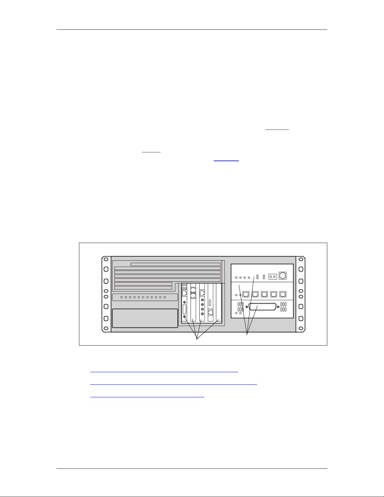
The main component of the Enterprise Edge system is the Enterprise Edge server.
The Enterprise Edge server controls all tasks such as call processing, voice
messaging, and data routing. The Enterprise Edge server also contains the
telephony and data networking components.
2
Media Bay ModulesPCI cards
The system components are summarized in:
• Enterprise Edge telephony hardware components on page 24
• Enterprise Edge data networking hardware components on page 24
• Enterprise Edge software components on page 25
For a detailed description of each hardware components, refer to the Enterprise
Edge Installation and Maintenance Manual.
P0911588 Issue 01 Enterprise Edge 2.0 Programming Operations Guide
Page 24

24 Enterprise Edge Overview
Enterprise Edge telephony hardware components
The telephony components perform call processing. These components also
connect the Enterprise Edge server to the Public Switched Telephone Network
(PSTN) lines and the Enterprise Edge telephones. The telephony hardware
components of the Enterprise Edge system include:
• Media Services Card (MSC), which is a PCI standard card that perform call
processing and media processing of the voice channels.
• Station set Media Bay Modules, which provide access to telephone lines. The
Enterprise Edge system includes the following station set media bay modules:
- 16-port Digital Station Media Bay Module (EE-DSM 16), which allows the
connection of 16 digital telephone sets to the system
- 32-port Digital Station Media Bay Module (EE-DSM 32), which allows the
connection of 32 digital telephone sets to the system
- Analog Station MediaBay Module (EE-ASM 8), which allows the connection
of analog station sets to the system (North American systems only)
• Trunk Media Bay Modules, which provide access to telecommunications
trunks. The Enterprise Edge system includes the following trunk media bay
modules:
- Digital Trunk Media Bay Module (EE-DTM), which provides the connection
between a standard digital PSTN T1 or PRI line and theEnterpriseEdge system.
- Caller ID Trunk Media Bay Module (EE-CTM), which provides the ability to
access four analog Caller ID PSTN lines. (North Americansystems only)
- Basic Rate Interface Media Bay Module (EE-BRIM S/T), which provides the
ability to access up to four BRI S/T ISDN lines.
- Fibre Expansion Media Bay Module (EE-FEM), which provides the ability to
access up to six Norstar expansion modules. These expansion modules add
PSTN lines and telephones to the Enterprise Edge system.
• S tation sets and adapters
Enterprise Edge data networking hardware components
The data networking components connect the Enterprise Edge server to the local
area network (LAN) and the wide area network (WAN). The data networking
hardware components of the Enterprise Edge system include:
• V.90 modem card used to send and receive data using the public telephone
system. ( North American systems only)
• LAN interface card to connect the Enterprise Edge system to the local area
network. This card is a 10/100 Base T Ethernet network interface card.
• WAN interface card to connect the Enterprise Edge system to the wide area
network. North American systems have a T1 interface port and a synchronous
port. European systems have two serial synchronous ports.
Enterprise Edge 2.0 Programming Operations Guide P0911588 Issue 01
Page 25

Enterprise Edge software components
The Enterprise Edge system provides a number of software applications. Some of
these applications work immediately after you install the Enterprise Edge system.
Touse other applications, you mustenable the application using software keycodes.
A software keycode is a password number provided to the installer. The Enterprise
Edge applications available are:
• Enterprise Edge Integrated Solution on page 25
• Enterprise Edge Voice Messaging on page 26
• Enterprise Edge Call Center on page 27
• Enterprise Edge Call Center Reporting on page 27
• Enterprise Edge Voice over IP gateway on page 27
• Enterprise Edge TSP on page 27
• Enterprise Edge Personal Call Manager on page 27
• Enterprise Edge Call Detail Recording on page 28
• Enterprise Edge Attendant Consol on page 28
Enterprise Edge Overview 25
• Enterprise Edge Integrated QoS Routing on page 28
For information on enabling software applications, refer to the Enterprise Edge
Software Keycode Installation Guide.
Enterprise Edge Integrated Solution
EnterpriseEdgeIntegrated Solution software supplies standard telephony operating
features plus the following additional features:
• Enterprise Edge Companion (North American systems only) on page 25
• Programming, administration and maintenance on page 25
Enterprise Edge Companion (North American systems only)
The Enterprise Edge Companion Wireless software provides wireless functionality
without losing the advantages of the wired system.The system can be programmed
so that users can publish one telephone number and receive all calls on both their
desk set and their portable, allowing them to answer the one who is most
convenient.
Programming, administration and maintenance
The Enterprise Edge Unified Manager software provides programming,
administration and maintenance. Enterprise Edge Unified Manager provides a
series of windows and menus which allow you to navigate through the different
areas of the application and program the system. For more information on Unified
Manager, refer to Unified Manager on page 28.
P0911588 Issue 01 Enterprise Edge 2.0 Programming Operations Guide
Page 26

26 Enterprise Edge Overview
Enterprise Edge Voice Messaging
Enterprise Edge Voice Messaging is a WindowsTMbased application that allows
the user to set up and administer the following Voice Messaging features:
• Voice messaging on page 26
• Enterprise Edge Auto attendant on page 26
• Custom Call Routing (CCR) on page 26
• Enterprise Edge Networking on page 26
• Enterprise Edge Unified Messaging on page 26
Voice messaging
Voice messaging records caller’s messages and stores them in a mailbox for easy
retrieval. Each Enterprise Edge telephone in your system can have its mailbox and
personal greeting.
Enterprise Edge Auto attendant
Auto attendant answers business calls with a Company Greeting. A voice prompt
then offers callers a menu of options to direct their call by selecting a digit on the
dial pad.
Custom Call Routing (CCR)
CCR replaces the Automated Attendant menu with a customized CCRHome Menu
to offer callers a wider range of call routing options and access to submenus and
information messages. CCR allows you to determine the menu options and record
the voice prompts that guide callers along call paths.
Enterprise Edge Networking
Enterprise Edge Networking includes General Networking parameters, Voice
Profile for Internet Mail (VPIM) parameters, Audio Messaging Interchange
Specification(AMIS)specificparametersandAMISSite Administration.Formore
information about Enterprise Edge Networking, refer to the Enterprise Edge
Networking Set Up and Operation Guide.
Enterprise Edge Unified Messaging
Enterprise Edge Unified Messaging includes three features:
• Enterprise Edge Unified Messaging allows you to create and receive
messages on your personal computer.
• Enterprise Edge Personal Mailbox Manager allows you to change mailbox
features and functions such as mailboxinitializationand target attendant, record
greetings, and set up and maintain off-premise message notification.
• Enterprise Edge Operator Manager allows you to change the Operator
password, change business status, enable or disable the system attendant and
enable or disable the Call Answer feature.
Enterprise Edge 2.0 Programming Operations Guide P0911588 Issue 01
Page 27

Enterprise Edge Overview 27
For more information, refer to the Enterprise Edge Unified Messaging Client
Installation Guide.
Enterprise Edge Call Center
The Enterprise Edge Call Center is an Automatic Call Distribution (ACD) system
designed to handle incoming calls. Incoming calls are distributed to available
agents or to Enterprise Edge greetings in your call center. To ensure that each call
is handled correctly, the Enterprise Edge Call Center system answers, plays
greetings and routes each incoming call to the first available agent in the order of
the call's arrival. For more information, refer to the Enterprise Edge Call Center Set
Up and Operation Guide.
Enterprise Edge Call Center Reporting
Enterprise Edge Call Center Reporting is a Windows software application that
provides Real Time statistics and complete management information on the daily
performance of your Enterprise Edge system. Enterprise Edge Call Center
Reporting helps you manage call traffic and provides a full range of management
reports that provides critical information for accurate business planning. It also has
the ability to support multiple Wallboards which can be configured separately to
display the information that the agents require. For more information, refer to the
Enterprise Edge Call Center Reporting Set Up and Operation Guide.
Enterprise Edge Voice over IP gateway
Enterprise Edge VoIP Gateway allows you to use IP telephony. VoIP Gateway
converts the voice in a call into a packet format that can be sent over an intranet.
With Enterprise Edge VoIP Gateway, you can make telephone calls over any
intranet connected to the Enterprise Edge system. For more information, refer to the
Enterprise Edge IP Telephony Configuration Guide.
Enterprise Edge TSP
Enterprise Edge TSP is the interface between the Enterprise Edge system and
Microsoft®1TAPI. This interface allows you to use TAPI applications on the
Enterprise Edge system. For more information, refer to the Enterprise Edge TSP
Server Configuration Guide.
Enterprise Edge Personal Call Manager
Enterprise Edge Personal Call Manager is a TAPI application that allows you to
control your Enterprise Edge telephone from your personal computer. For more
information, refer to the Enterprise Edge Personal Call Manager User Guide.
1.Microsoft is a registered trademark of Microsoft Corporation.
P0911588 Issue 01 Enterprise Edge 2.0 Programming Operations Guide
Page 28

28 Enterprise Edge Overview
Enterprise Edge Call Detail Recording
The Enterprise Edge Call Detail Recording software records call activity. When a
telephone call is made to or from your company, the information about the call is
recorded. When the call is completed, information about the call is printed out in
Call Records. For more information, refer to the Enterprise Edge Call Detail
Recording System Administrator Guide.
Enterprise Edge Attendant Consol
Enterprise Edge Attendant Console uses a graphical user interface to provide
centralized call management. For more information, refer to the Enterprise Edge
Attendant Console Set Up and Operation Guide and the Enterprise Edge Attendant
Console User Guide.
Enterprise Edge Integrated QoS Routing
Enterprise Edge Integrated QoS Routing controls the interface between the
Enterprise Edge system and the local area network, wide area network, and Internet.
Tivoli
Tivoli provides inventory management, multi-site software distribution and
service level and status monitoring. All Enterprise Edge systems are sold with an
imbedded Tivoli Management Agent (TMA) that allows Enterprise Edge to
connect to a central server where the software resides. When installed, all
Enterprise Edge systems automatically register with the central TMR server. For
more information, refer to System registration on page 42.
Optivity
Optivity allows the customer to view the topology of the network including the
Enterprise Edge, other routers, hubs, switches and servers and see how the
different devices are connected and performing. The Optivity management station
can be used to capture SNMP alarms sent from Enterprise Edge. Unified Manager
can be launched from within the Optivity Management Tool suite. For more
information, refer to the Optivity documentation
Unified Manager
The Enterprise Edge Unified Manager provides a web-based navigation tool that
lets you view and change configuration for:
• system settings
• IP Services
• VoIP Service
• Telephony Services
• Management Server Module
Enterprise Edge 2.0 Programming Operations Guide P0911588 Issue 01
Page 29

Enterprise Edge Overview 29
• QoS Module
• Diagnostics
Most changes made with Unified Manager become part of current Enterprise Edge
programming when you select an item from the menu options. However, some
changes take effect a minute after the user stops programming. If a programming
error occurs, you must reenter the original programming.
For more information on Unified Manager, refer to
• Browser requirements on page 29
• Understanding Unified Manager on page 30
• Enterprise Edge system access on page 32
Browser requirements
Your computer must meet the following requirements to configure Enterprise Edge
through the Unified Manager.
• WinNT or Windows workstation running on P133 or higher CPU (or
compatible)
• 64MBRAM,10MBdiskspace
• Minimum screen definition of 1024 X 768
• Minimum monitor size of 17 inches
To use Enterprise Edge Unified Manager, you must have:
• Java Virtual Machine (JVM) 5.0 (build 5.0.0.3188 or greater)
• One of the following web browsers:
Netscape Communicator 4.5 or greater
Microsoft Internet Explorer 4.0 or greater
If you are using Netscape Communicator, you must set the following parameters:
• Enable Java: On
• Cached document comparison: Every time
If you are using Microsoft Internet Explorer, you must set the following parameters:
• C heck for newer versions: Every visit to the page
• Java JIT compiler enabled: On
For information about setting these parameters, refer to theuser documentation that
came with your web browser.
P0911588 Issue 01 Enterprise Edge 2.0 Programming Operations Guide
Page 30

30 Enterprise Edge Overview
Understanding Unified Manager
Unified Manager consists of:
• a menu bar where users access configuration commands
• a navigation frame where is located the navigation tree that allows you to
navigate through Enterprise Edge programming headings
• aninformation frame that displays the windows that relates to the headings you
select in the navigation frame
menu bar
navigation
tree
navigation
keys
buttons
heading
nnavigation
frame
window
information
frame
The menu bar contains configuration management options. These options are
enabled when you select the different headings in the navigation tree to enter
specific areas of the Enterprise Edge system. If an option is dimmed, it is not
available for the heading you have selected.
The navigation tree contains headings that allow you to access specific areas of the
Enterprise Edge system. The key symbol ( ) beside each heading indicates that the
heading can be expanded to show sub-headings. To make sub-headings appear,
double-click the item or just click on the key itself. As you select various headings
in the navigation tree, the heading changes color and Unified Manager displays the
appropriate information frame.
The information frame can contain configuration windows or dialog boxes
indicating the appropriate action and system messages or warnings.
For more detailed information on Unified Manager, refer to:
• Using the configuration windows on page 31
• Changing data views in Unified Manager on page 31
Enterprise Edge 2.0 Programming Operations Guide P0911588 Issue 01
Page 31

Enterprise Edge Overview 31
Using the configuration windows
The configuration windows are used to configure Enterprise Edge settings. The
configuration windows always contain a window identifier. Some fields use editin-place formats to allow you to configure settings in the box opposite each box
name. When you tab to the next box, the previous box values are saved. Some box
use drop-down list to provide you with valid entries.
If a value is invalid, an error message appears to alert you of the error. The dialog
box format allows you to enter text in boxes and save the settings by clicking the
Save button where available or by simply moving to another heading in the
navigation tree.
window identifier
field names
text fields
Changing data views in Unified Manager
You can change the order and size of data views in the Unified Manager.
Use the following procedure to change the column order.
1. Point to the column that you want to move and click on it.
2. Holding the mouse down, drag and drop the column to the appropriate
location.
The other column in this location, automatically changes places w ith the
column you are moving.
Use the following procedure to change the column width of any column in the
display.
1. Keeping the pointer in the heading row, move it over any column edge until it
changes to a double-headed arrow.
2. Drag the column edge to the appropriate location.
P0911588 Issue 01 Enterprise Edge 2.0 Programming Operations Guide
Page 32

32 Enterprise Edge Overview
Menu descriptions
You access Enterprise Edge functions using the menu. The menu is dynamic which
means that the menu commands change depending on the heading you select from
the navigation tree.
Menu descriptions
Use To
Group View the system, resources, services, and management.
Edit Edit parameters.
Configuration Access configuration dialog boxes and screens.
Performance Access performance graphs and tables.
Fault Access fault management settings.
Report Generate a report.
Tools Use Enterprise Edge tools.
Logoff Log off, reboot or shutdown the Enterprise Edge server.
View Refresh the information window to reflect configuration changes.
Help Access online help.
Enterprise Edge system access
Note: System access must be controlled by providing one userid, the
administrator, with read-write privileges. All other users must be given
read-only privileges. This prevents concurrent configuration of the
Enterprise Edge system. For information on defining user profile and
password, see User Manager on page 253
The Unified Manager’s navigation tree contains five main headings that allow you
to access specific areas of the Enterprise Edge system. The main headings are:
• System on page 32
• R esources on page 33
• Services on page 33
• Management on page 33
• Diagnostics on page 33
System
When you select the System heading, you can view system information such as
your system name and description and which resources and services are available.
When you select the System heading, the following menu options are enabled:
Configuration,Performance, Fault, Logoff, View andHelp.These menu options
provide access to statistical information, allow you to enable or disable services and
perform system reboot or shutdown. For more information on configuring your
system settings, refer to the Configuring system settings on page 41. For
information on Performance and Fault monitoring, refer to Viewing system
performance and fault alarms on page 307 and Enterprise Edge system diagnostics
and utilities on page 269.
Enterprise Edge 2.0 Programming Operations Guide P0911588 Issue 01
Page 33

Enterprise Edge Overview 33
You can expand the navigation tree under the System headingtofindtheLicensing
and the Identification subheadings.
Resources
The subheadings under the Resources heading, allow you to configure the
following resources:
•LAN
•WAN
• Media Services Card
• Media Bay Modules
•DialUp
For more information on resource programming, refer to Configuring Enterprise
Edge Resources on page 45.
Services
Use the options unde r the Servicesheading to configure services for the Enterprise
Edge system, including telephony services. For more information on configuring
these settings, refer to Configuring Enterprise Edge Services on page 83.
Management
Use the options under the Managementheadingto configure network management
parameters for User Manager and Alarm Manager. For more information, refer to
Configuring Management Settings on page 253.
Diagnostics
Use the options under the Diagnostics heading to generate and access statistics on
different system components. Enterprise Edge provides various statistics, metrics
and event logs on resources and services to help you carry out system maintenance
activities. For more information on using diagnostics tools, refer toMaintenance on
page 259.
P0911588 Issue 01 Enterprise Edge 2.0 Programming Operations Guide
Page 34

34 Enterprise Edge Overview
Enterprise Edge 2.0 Programming Operations Guide P0911588 Issue 01
Page 35

Setting up your Enterprise Edge system
Refer to the following information when setting up your Enterprise Edge system.
• Enterprise Edge required parameters on page 35
• Setting up an Enterprise Edge IP Address on page 36
• Setting up web-based administration on page 37
• Logging on to Enterprise Edge on page 37
• Logging off Enterprise Edge on page 40
• Rebooting the Enterprise Edge server on page 40
• Shutting down Enterprise Edge System on page 40
• Licensing on page 41
• Configuring system settings on page 41
• System registration on page 42
3
Enterprise Edge required parameters
The Enterprise Edge quick start module provides quick access to the parameters
necessary for the Enterprise Edge server to become active online. However, you
must enter a minimum set of parameters within the quick start module. For more
information, see the Enterprise Edge Installation and Maintenance Guide.
Obtain the required parameter values from an Internet Service Provider (ISP) or
corporate network administrator.
Note: Configure all the required parameters during the initial configuration
session after you power on the Enterprise Edge server and connect with
either an RS-232 or an Ethernet port. After you configure the parameters,
reboot the Enterprise Edge server from either the console or Unified
Manager.
Enterprise Edge required parameters are:
• Initial IP address and mask for each network interface
• Primary (and optional secondary) DNS servers
• Default next-hop router
• Fractional T1 channel numbers (if you are using fractional TI)
• S ystem name
• WAN link protocol
• Frame Relay DLCI / CIR (if applicable)
P0911588 Issue 01 Enterprise Edge 2.0 Programming Operations Guide
Page 36

36 Setting up your Enterprise Edge system
• V.90 modem dial-up username and password (North America only)
• V.90modemdial-upphone numberand optional alternate phone number (North
America only)
The following table describes the Enterprise Edge server connectivity options.
Field Definition
HTTP You can connect to Enterprise Edge from your PC using your JAVA-enabled
Internet browser.
TTY Youcan connect a dumb terminal to the console of the Enterprise Edge server
through an RS-232 cross-over cable, or you can use Hyperterminal from Win95/
Win NT systems. Refer to the appropriate installation guide for information on
how to use the console menus.
Setting up an Enterprise Edge IP Address
To manage the Enterprise Edge server using a web browser or an RS-232
connection, you must first set up the IP address. The Enterprise Edge server LAN
interface is shipped with default IP address 10.10.10.1 and mask 255.255.255.0.
You can change the Enterprise Edge IP address using
To set up the Enterprise Edge server initial IP address using a RS-232 port:
1. Plug in the Enterprise Edge server.
2. Connect a PC or laptop computer to the Enterprise Edge server RS-232 port
using a null modem cable.
3. Start a HyperTerminal session on the PC or laptop computer.
4. Enter the LAN/WAN IP address and all other required parameters.
To set up the Enterprise Edge server IP address using a LAN:
1. Plug in the Enterprise Edge server.
2. Connect a laptop to the Enterprise Edge server by Ethernet (back-to-back by
using a crossover cable to avoid disturbing the corporate LAN).
3. Set your PC or laptop computer IP address to 10.10.10.2 with a mask
255.255.255.0.
4. Start a web browser on your laptop with a URL of 10.10.10.1.
Enterprise Edge 2.0 Programming Operations Guide P0911588 Issue 01
Page 37

Setting up your Enterprise Edge system 37
Setting up web-based administration
You can establish web-basedadministration to managethe Enterprise Edge system
using Unified Manager. Your PC must be set up as an Enterprise Edge client with
Internet Explorer 4.0 or greater and a JAVA Virtual Machine (JVM) 5.0.0.3188 or
greater installed.
To install JVM on a workstation, search the Microsoft information web page for
instructions.
For information on minimum computer or software requirements refer to the
Enterprise Edge Installation and Maintenance Guide.
Note: The ideal display setting for a monitor attached to Enterprise Edge is
1280 x 1024.
Browser settings
Set your browser as follows:
Program Required Settings
Netscape Communicator 4.5
or greater
Internet Explorer 4.0 or
greater
Enable Java: On
Category: Cache
Cached document comparison: Every Time
Check for newer versions of stored pages: Every visit to the page
Advanced Java VM
Java JIT compiler enabled
Unified Manager allows multiple users to log on to the Enterprise Edge system. If
more than one user log on to configure the same or related subsystems, the most
recent modification remains in effect and overwrites changes previously made.
Maintain one user profile with system administrator privileges. If you have more
than one system administrators, you must plan configuration changes carefully. For
information on managing user profile and system access, see User Manager.
Note: When configuring Enterprise Edge using Unified Manager, you must
disable proxies and directly access Enterprise Edge. The procedure to
disable proxies depends on the browser and version.
Logging on to Enterprise Edge
You can access the Enterprise Edge system from another computer through a
WAN/Internet connection or a dialup connection. The dialup connection uses either
the built in V.90 modem (North America only) or an ISDN dialup. Either access
method creates an IP connection that enables all IP-based management tools. For
more information on remote connections, refer to Dial Up on page 58.
Use the following procedure to log on to Enterprise Edge using the web browser:
P0911588 Issue 01 Enterprise Edge 2.0 Programming Operations Guide
Page 38

38 Setting up your Enterprise Edge system
1. Launch your web browser.
2. In the URL address field, type the Enterprise Edge IP address and add port
6800.
For example: HTTP://10.10.10.1:6800
The Enterprise Edge Unified Manager initial page is displayed.
3. Click the Configure button.
The Enterprise Edge login screen appears.
4. In the Login box, type your login name.
The default login name is supervisor.
5. In the Password box, type your password.
The default password is visor.
Tips
Make sure to change the password after you first log on to Enterprise Edge.
For information on how to change passwords and to define user profiles, see
User Manager on page 253.
6. Click the Connect button.
The Enterprise Edge Unified Manager software starts. Depending on your
system, Unified Manager software can take up to several minutes to initialize.
Tips
Performance at startup of Unified Manager is enhanced by preloading the Java
class files on all PCs and laptops from which you want to access Enterprise
Edge using Unified Manager. Prelaoding the Java class files on your
workstation saves time because the Enterprise Edge server does not need to
download Java class files to your PC when you launch Unified Manager. See
Preloading Java class files on your workstation.
The login screen includes:
Field Definition
Login Allows you to enter the user name. The name can contain up to 50 case-sensitive
alphanumeric characters. The default log in name for a system administrator is
supervisor.
Password The Enterprise Edge password associated with the login name. The password can
contain up to 12 case-sensitive alphanumeric characters. The default system
administrator password is visor.
Configure Allows you access Enterprise Edge configuration.
Enterprise Edge 2.0 Programming Operations Guide P0911588 Issue 01
Page 39
Setting up your Enterprise Edge system 39
Preloading Java class files on your workstation
To preload Java class files on your workstation:
1. From your PC Start menu, choose Find and then Computer...
2. In the Named: box, enter your Enterprise Edge system name.
Tips
If you do not know your Enterprise Edge system name, log on to Enterprise
Edge the usual way using Unified Manager and from the navigation tree, click
System. The system name is displayed in the System Name box.
3. Click Find Now.
4. Double-click on the computer icon.
The NortelDT folder is displayed.
5. Open the NortelDT folder.
6. Open the Unified Manager IE Client or Unified Manager Netscape Client
folder, depending on which Internet browser you use to access Enterprise
Edge Unified Manager.
7. Double-click on the Setup.ex icon to install the client software on your
computer.
Accessing Unified Manager through the Preinstalled Client Home Page
Tips
To access Unified Manager through the Preinstalled Client Home Page, you
must first preload the Java class files on your PC. See
class files on your workstation.
1. Lauch you browser and enter your Enterprise Edge IP address followed by
port 5800. For example: http://10.10.10.1:6800
The Enterprise Edge Unified Manager initial page is displayed.
2. From Enterprise Edge home page, click the Preinstalled Client Home Page
hyperlink.
Preloading Java
3. Click the Configure button to access Unified Manager.
P0911588 Issue 01 Enterprise Edge 2.0 Programming Operations Guide
Page 40

40 Setting up your Enterprise Edge system
Logging off Enterprise Edge
To log off Enterprise Edge:
1. Choose Enterprise Edge in the navigation tree.
The Logoff menu is enabled.
2. From the Logoff menu, click Logoff.
A message appears that asks you to confirm your request to log off.
3. Click Yes to log off.
Rebooting the Enterprise Edge server
To reboot the Enterprise Edge server:
1. Choose System in the navigation tree.
The Logoff menu is enabled.
2. On the Logoff menu, click Reboot.
A message appears that asks you to confirm your request to reboot.
3. Click the Yes button to reboot.
Shutting down Enterprise Edge System
To shut down the Enterprise Edge System:
1. From the navigation tree, choose System.
The Logoff menu is enabled.
2. On the Logoff menu, click Shutdown.
A message appears that asks you to confirm your request to shut down the
system.
All Enterprise Edge services stop when performing system shutdown
Performing a system shutdown stops all Enterprise Edge applications and
services, including IP telephony. Active IP telephony calls fall back on the
PSTN if you have programmed your system to do so.
3. Click the Yes button to shut down the system.
A Shutdown process status window is displayed and the Done button is
enabled.
Enterprise Edge 2.0 Programming Operations Guide P0911588 Issue 01
Page 41

Setting up your Enterprise Edge system 41
4. Click the Done button.
When the shutdown is completed, your browser loses the connection with
Enterprise Edge.
Tips
The Enterprise Edge system automatically restarts 45 seconds after the Power
LED turns off. Disconnect Enterprise Edge power cord from the AC outlet if
you do not want the system to restart withing this period of time.
Licensing
The Licensing heading in Unified Manager allows you to view Enterprise Edge
unique System Identification Number.
To view the System Identifier:
1. Choose System, Licensing.
The System Identifier is displayed in the System section.
Entering the software keycodes
To enable software packages other than the base package, you need a security
keycode. Each security keycode contains three eight-digit numbers. For
information about how to obtain System Identification numbers, see the Enterprise
Edge Software Keycode Installation Guide.
To enable a software package:
1. Select System, Licensing.
2. On the Configuration menu, click Add a keycode. A dialog box appears.
3. In the Keycode box, type the 24-digit number in the following format:
xxxxxxxx-xxxxxxxx-xxxxxxxx.
4. Click Save.
Configuring system settings
You configure your system settings using the Group menu selection in the
upper-left corner of your screen.
1. Choose Group and then choose System or Comprehensive.
2. Click the System key to expand the navigation tree.
The Licensing and Identification headings appear.
P0911588 Issue 01 Enterprise Edge 2.0 Programming Operations Guide
Page 42

42 Setting up your Enterprise Edge system
3. Click Identification.
The Identification window is displayed.
4. Use the following table to configure the System Identification settings:
Setting Definition
System Name Allowsyou to assign a name to the Enterprise Edge system. Each Enterprise
Edge system on a network must have a unique name. The name must not
exceed 15 characters in length and must not contain special characters like
“/;,”.
Description Shows a description of the Enterprise Edge system.
Date Allows you to set the current date. Because the value for the date changes,
save the changes by pressing TAB as soon as the new date is entered.
Time Allows you to set the current time. Because the value for the time keeps
changing, save the changes as soon as the new time is entered. Use the 24-
hour format to set the time. The seconds field is optional.
Time Zone Allows you to select the local time zone for your system.
Country Allows you to select the country you are in.
Current Domain
Name
New Domain
Name
Next Hop to NT
Domain Controller
for TAPI
Allows you to enter the name of the domain on which your Enterprise Edge
system is currently registered. You must add Enterprise Edge to the domain
controller before y ou add the current domain name.
Allows you to enter the new name of the domain on which your Enterprise
Edge system is registered. You must add Enterprise Edge to the domain
controller before you enter the new domain name.
Enter the IP address of the next hop to reach the domain controller for TAPI.
Note: For information on configuring Enterprise Edge resources and services,
refer to Configuring Enterprise Edge Resources on page 45, and
Configuring Enterprise Edge Services on page 83.
System registration
When your Enterprise Edge system is installed and operational, it registers specific
information with a Tivoli Management Region (TMR) server. The goal of
registration is to build a customer profile containing system inventory information
which can then be used to bring you enhanced support and value-added services.
Note: To allow automatic registration, you must connect the system to the internet.
In North America, you also have the option to connect your system to an
analog line (PSTN) to establish a dial-up connection using the v.90 modem.
The system makes repeated call attempts every 24 hours until it connects to
the Tivoli server. The repeated a ttempts the system makes to make a
connection are transparent to your use of the system. For information on
how to connect the installed v.90 modem to a telephone line, refer to the
Enterprise Edge Installation and Maintenance Guide.
Enterprise Edge 2.0 Programming Operations Guide P0911588 Issue 01
Page 43

Setting up your Enterprise Edge system 43
Basic registration using Internet Access
For basic system registration using the public Internet, the system needs direct
access to the Internet (without going through a firewall). If access to the Internet is
through a firewall, the following configuration rules must be set on the firewall:
• F or traffic coming from the Enterprise Edge, allow all UDP and TCP traffic to
the Nortel Tivoli Gateway (192.122.98.36) on ports above 1023.
• From the Nortel Tivoli Gateway (192.122.98.36) allow TCP traffic to
Enterprise Edge on port 9495.
Basic Registration using v.90 modem (North America only)
Refer to the Enterprise Edge Installation and Maintenance Guide for information
on how to setup the Enterprise Edge v.90 modem.
The following information is automatically collected:
• System ID
• System Hardware list
• System Software list
• Operating system details
P0911588 Issue 01 Enterprise Edge 2.0 Programming Operations Guide
Page 44

44 Setting up your Enterprise Edge system
Enterprise Edge 2.0 Programming Operations Guide P0911588 Issue 01
Page 45

Configuring Enterprise Edge Resources
This chapter provides information on configuring Enterprise Edge resources. The
following shows the programming map for Enterprise Edge telephony and
networking resources:
Resources
Resources
LAN
LAN
LAN1
LAN1
WAN
WAN
WAN1
WAN1
WAN2
WAN2
Media Services Card
Media Services Card
DSP Current Configuration
DSP Current Configuration
DSP Manager
DSP Manager
DSP Settings
DSP Settings
Media Bay Modules
Media Bay Modules
Bus 02
Bus 02
Modules on Bus
Modules on Bus
Module 1
Module 1
Module 2
Module 2
Module 3
Module 3
Module 4
Module 4
Bus 03
Bus 03
Bus 04
Bus 04
Bus 05
Bus 05
Bus 06
Bus 06
Bus 07
Bus 07
Bus 08
Bus 08
Dial Up
Dial Up
V.90 modem (North America)
Dial Up
V.90 modem (North America) Dial Up
ISDN Dial Up
User2
isdnbackup
4
Note: The resources listed on this table may not correspond exactly at the
resources available on your Enterprise Edge system.
For information on how to view the Enterprise Edge resources available on your
system, refer to Viewing Enterprise Edge resources on page 45.
Viewing Enterprise Edge resources
Unified Manager lets you view and configure Enterprise Edge networking
resources including LAN, WAN, and dial up resources such as ISDN or V.90
modem (North America). To view the networking resources your Enterprise Edge
system supports:
1. On the Group menu, click Resources or Comprehensive.
2. On the navigation tree, click Enterprise Edge, and then click Resources.
The available Enterprise Edge resources appear in a table format.
P0911588 Issue 01 Enterprise Edge 2.0 Programming Operations Guide
Page 46

46 Configuring Enterprise Edge Resources
The Resources table contains the following information:
Attribute Description
Name Provides a list of available resources.
Status Shows the operating status of each resource.
Version Shows the software version of each resource.
Description Provides a description of the interface card for each resource.
LAN
Enterprise Edge is equipped with an Ethernet/802.3 network interface card which
supports the IEEE 802.3 Ethernet frame format. The Ethernet connection uses
CarrierSense Multiple Access with Collision Detection (CSMA/CD) to manage the
access to the physical media.
The Enterprise Edge Ethernet interface card supports the following features:
• 100 BASE – TX with RJ-45 connector
• 10/100AutoSense
• F ull Duplex
• Fast LAN-to-LAN routing (when using more than one LAN cards)
• LAN traffic smoothing
Viewing LAN resources and configuring global LAN attributes
Enterprise Edge Unified Manager shows all available LAN resources. If your
Enterprise Edge server is equiped with two LAN interface cards, Unified Manager
displays all available LAN resources and numbers each one (LAN1, LAN2).
To view the available LAN resources and configure global LAN attributes:
1. Select LAN from the navigation tree. Unified Manager displays the global
LAN Parameters and the Resources table showing available LAN cards.
Configuring LAN resources
Setting LAN global parameters
1. ClickontheResources heading to expand the navigation tree.
The available resouces appear.
2. Click LAN.
The Lan Parameters and Resources windows appear.
Enterprise Edge 2.0 Programming Operations Guide P0911588 Issue 01
Page 47

Configuring Enterprise Edge Resources 47
3. Set your global LAN parameters according to the following table:
Attribute Description
Fast Routing
(Between LANs)
Decrement TTL When Fast Routing is enabled, Decrement TTL lets you decrement the time-
Traffic Smoothing
(In Mbps)
Allows you to enable or disable fast routing to improve LAN-to-LAN
routing performance. This feature is for an Enterprise Edge system equipped
with two LAN cards. At the same link speed, a smaller packet size means
more packets t o forward. Use a lower traffic threshold. For more
information on Fast Routing, see
smoothing. Permitted values: Enabled or Disabled
Default: Disabled
to-live (TTL) value in the IP header of packets as they travel from LAN to
LAN. Decrement TTL lets you increase processing time for each fast-routed
IP packet, which reduces CPU cycles. This feature is used when other
routers or special applications on the network connect to the LAN interfaces.
Permitted Values: Enabled or Disabled
Default: Disabled
Lets you set the rate, in Mbps, at which the LAN driver receives packets
from the LAN interface. The main purpose of this feature is to limit the
number of host CPU cycles spent on LAN-to-WAN packet forwarding.
Normally, LAN drivers operate at link speed, which implies that the driver
forwards packets as fast as possible until there is no packet in the receiving
buffer.
Permitted values: 5, 10, 15, 20, 25, 30, 35, 40, 45, 50, Disabled
Default: 40
Guidelines to configure LAN to LAN traffic
Guidelines to configure LAN to LAN traffic smoothing.
64 bytes 128 bytes 256 bytes 512 bytes 1024 bytes 1500 bytes
Fast Routing
enabled
Fast Routing
disabled
or
LAN-to-WAN
routing
40 mbps 50 mbps 50 mbps 50 mbps Not needed Not needed
10 mbps 15 mbps 30 mbps 50 mbps 50 mbps 50 mbps
Note: The settings shown in the table above ensure data routing uses a maximum
of 60 to 70 percent CPU cycles (Celeron 366MHz processor).
Note: If the LAN to WAN link speed is 10 mbps, selecting higher traffic
smoothing parameters has no impact on packet forwarding, which the
system still performs at a link speed of 10 mbps.
Configuring a LAN interface
LAN1
To configure LAN1 or any other LAN interface:
1. Click the LAN navigation key to expand the navigation tree.
The available LAN interfaces appear.
P0911588 Issue 01 Enterprise Edge 2.0 Programming Operations Guide
Page 48

48 Configuring Enterprise Edge Resources
2. Click LAN1. Unified Manager displays the LAN Summary screen for LAN1.
3. Configure the LAN1 attributes according to the following table.
Attribute Description
IP Address Enter the IP address of the LAN interface in the following format:
255.255.255.255.
If you do not know your LAN interface IP address, contact your system
administrator or your Internet s ervice provider.
SubNet Mask Enter the subnet mask of the LAN interface in the following format:
255.255.255.255.If you don’t know your subnet mask address, contact your
system administrator or your Internet service provider.
Physical Address Shows the physical address of the LAN interface.
Description Provides a description of the network interface card supporting the LAN
connection.
Version Shows the version of the LAN interface card.
Speed Shows the speed of the connection to the LAN interface.
Connection Type Lets you select a type of connection to the LAN interface.
The following values are supported and are interpreted as follows:
Auto Sense: The LAN interface uses the auto negotiationprotocol to choose
the maximum possible speed of the connection. Depending on the connected
device, the LAN can choose 100 MB or 10MB, full-duplex or half-duplex.
10 MB Half: The speed is set to 10 Mbit/s and mode to half-duplex.
10 MB Full: The speed is set to 10 Mbit/s and mode to full-duplex.
10 MB Auto: The speed is set to 10 Mbit/s and the mode (half-duplex or
full-duplex) is automatically selected by the interface, using the auto
negotiation protocol. The 10MB Auto connection type limits the maximum
traffic coming into Enterprise Edge to 10 Mbit/s, and enables the auto
negotiation feature for easier interconnection. Limit the incoming traffic if
you notice that the bursty traffic from the connected LAN is degrading the
quality of voice calls carried through VoIP over the WAN. Though the LAN
traffic gets lower priority in Enterprise Edge, a high incoming traffic to the
Enterprise Edge server can result in service interruptions in the system,
which degrades the quality of voice calls carried as VoIP.
100 MB Half: The speed is set to 100 Mbit/s and mode to half-duplex.
100 MB Full: The speed is set to 100 Mbit/s and mode to full-duplex.
Default value: Auto Sense
Status Shows the current status of the LAN connection.
Thepossiblestatesare:
Up: The resource is operational.
Down: The resource is not operational.
Note: Consult your System Administrator for the appropriate configuration
information before changing the settings.
Enterprise Edge 2.0 Programming Operations Guide P0911588 Issue 01
Page 49

Configuring Enterprise Edge Resources 49
Note: Because the Enterprise Edge WAN interface has a maximum bandwidth of
1.544 Mbit/s (T1) or 2.048 Mbit/s (E1), setting the LAN connection speed
to 10 Mbit/s does not reduce performance. However, the CPU is more
efficient if you limit your incoming traffic to 10 Mbit/s. To increase your
CPU performance, set the connected external LAN hub or switch to
10 Mbit/s or to Auto Sense.
Note: If you enable LAN Traffic Smoothing, the connection type defaults to
Auto Sense and there is no requirement on the external LAN hub or switch.
To view LAN performance:
1. From the LAN1 summary screen, on the menu, click Performance and then
click LAN Graph.
The LAN Graph: Statistic Chart screen is displayed.
2. On the menu, click Performance andthenclickLAN Table.
The LAN Table: Statistic Table screen is displayed.
WA N
WAN Overview
A WAN (wide area network) is a geographically dispersed data communication
network. The term WAN distinguishes a broader data communication structure
from a local area network (LAN). A WAN can be privately owned or rented, but
usually connotes the inclusion of public (shared user) networks.
Enterprise Edge is equipped with a SDL WAN Series 500 interface card with two
serial synchronous ports (Europe), or a SDL WAN Series 550 interface card with
one T1 port (with integrated CSU/DSU) and one serial synchronous port (North
America). Each port from the WAN interface provides a primary WAN connection
(WAN1, WAN2). The serial synchronous port supports the following:
• North America: V.35
• Europe: V.35 (Upper Sync Port) and X.21 (Lower Sync Port)
• Maximum line speed: 8 Mbit/sec.
Enterprise Edge provides primary and backup WAN links through dial-up
connections using a V.90 modem (North America) or ISDN BRI/PRI. For
information on V.90 modem or ISDN connections, see Dial Up. Net Link Manager
provides continuous WAN connection status monitoring. For information on Net
Link Manager, see Net Link Manager on page 229.
P0911588 Issue 01 Enterprise Edge 2.0 Programming Operations Guide
Page 50

50 Configuring Enterprise Edge Resources
Permanent WAN Connection
The permanent WAN connection is exposed as a dedicated network adapter. The
permanent link supports frame relay or Point-to-Point protocol (PPP) at the link
layer. The link protocol used depends on the existing network or on the service you
buy from your Internet service provider. The two ports provided by the SDL WAN
interface card can be independently configured to run frame relay or PPP.
Frame Relay
Enterprise Edge supports frame relay in groupmode. That is, for each physical port
(serial sync or T1 port), there is one IP address for all PVCs (permanent virtual
circuits). The available Data Link Control interface numbers are 0-1023. Of the
1023 PVCs, 16 are reserved. The maximum number of PVC’s allowed is 1008.
For a frame relay network, Enterprise Edge supports the Frame Relay Forum
standard FRF.9 compression protocol with the standard STAC compression
algorithm. Enterprise Edge software performs the compression. For information on
enabling or disabling WAN data compression, see WAN Data Compression on
page 50.
Point-to-Point-Protocol (PPP)
Point-to-Point Protocol (PPP) is a full-duplex transmission protocol for
communicationbetween two computers using a serial interface, typically apersonal
computer connected by telephone line to a server. For example, your Internet
service provider (ISP) can provide you with a PPP connection so that the ISP’s
server can respond to your requests, pass them on to the Internet, and return your
requested Internet responses to you. PPP uses theInternet protocol (IP).
Enterprise Edge supports PPP Compression Control Protocol (CCP) (RFC 1962)
with STAC compression algorithm. This compression is done by Enterprise Edge
software and can be enabled or disabled using a parameter in PPP configurations.
For information on WAN data compression, see WAN Data Compression on page
50.
WAN Data Compression
Enterprise Edge provides a WAN Data Compression feature. You can use data
compression on permanent WAN connection and on backup WAN connection. By
default, WAN Data Compression is enabled on Enterprise Edge. WAN Data
Compression can be enabled or disabled from the Setting WAN Frame Relay
Parameters screen or from the WAN PPP Parameters screen, depending on your
system configuration.
On a permanent WAN connection, Enterprise Edge supports the following data
compression protocol:
• Frame Relay Forum standard FRF.9 data compression protocol with de facto
standard STAC compression algorithm
• PPP Compression Control Protocol (RFC 1962) with STAC compression
algorithm
Enterprise Edge 2.0 Programming Operations Guide P0911588 Issue 01
Page 51

Configuring Enterprise Edge Resources 51
On dial-up WAN connections, Enterprise Edge supports the following data
compression protocol:
• Microsoft Point-to-Point Compression (MPPC), RFC 2118
Viewing WAN Resources
Enterprise Edge lets you view available WAN resources.
To view available WAN resources:
1. From Unified Manager, under Resources, click WAN. The Resources section
displays the WAN interfaces (WAN1, WAN2) in a table format.
Setting global WAN parameters
If PPP is the link protocol for a WAN interface (WAN1 or WAN2), you can use an
authentication process to identify the user requesting a network connection. The
authentication process involves creating a list of user names and assigning
passwords using the PPP Password List. Enterprise Edge uses the information on
the list to verify and confirm the identity of the user. Only those users whose names
appear on the PPP Password List can access the network. The PPP Password List
configuration lets you add, modify or delete an item on the list.
To create a PPP Password List:
1. From the WAN Resources section, scroll down to the PPP Password List.
2. From the menu click Configuration and select Add PPP User&Password.
The PPP Password List dialog box appears.
3. In the P# box, type the number of the list item. For example, if you are adding
the first item on the list, the P# is P1.
Note: If you type an item number which already exists in the list, the
following message appears "You tried to add a row with existing key".
Assign a new number to the item to want to add to the list.
4. In the PPP User Name box, type the user name associated with the computer
you want Enterprise Edge to identify as a valid network user.
Note: You must overwrite the default user name User with the user name
you want to add to the list.
5. In the PPP Password box, type the password you want to assign to the user
defined in the PPP User Name box. The password can contain a combination
of lowercase and uppercase letters and numbers.
6. Click Save to save your settings.
P0911588 Issue 01 Enterprise Edge 2.0 Programming Operations Guide
Page 52

52 Configuring Enterprise Edge Resources
To modify an existing item on the PPP Password List:
1. From the list, click the item you want to modify. The selected item is
highlighted.
2. From the menu, click Configuration and select
Modify PPP User&Password. The PPP Password List dialog box appears.
3. Make the necessary changes.
4. Click Save to save your changes.
To delete an item from the PPP Password List:
1. From the list, select the item you want to delete. The selected item is
highlighted.
2. From the menu, click Configuration and select
Delete PPP User&Password. A dialog box appears to ask "Are you sure you
want to delete this row?" Click Yes.
Configuring WAN Summary Parameters
1. Click the WAN navigation key to expand the navigation tree.
2. On the navigation tree, click WAN1 or WAN2. Unified Manager displays the
following screens: WAN Line Parameters (if you are configuring a T1 port
[North America only]), WAN Frame Relay or PPP Parameters (depending on
the link protocol selected), and PVC Congestion Control screens.
Note: Clicking the WAN1 or WAN2 navigation key causes the key to
disappear. You must click WAN1 or WAN2 to access the WAN
Summary screen.
3. Use the attributes in the following table to configure Enterprise Edge WAN
Summary settings:
Attribute Description
IP Address Enter the IP address of the WAN interface. The WAN IP address must be in
the following format: 255.255.255.255.
You can obtain this information from your system administrator or your
Internet service provider.
SubNet Mask Enter the subnet mask address of the WAN. The subnet mask IP address must
be in the following format: 255.255.255.255.
You can obtain this information from your system administrator or your
Internet service provider.
Physical Address Shows the physical address of the WAN interface.
Enterprise Edge 2.0 Programming Operations Guide P0911588 Issue 01
Page 53

Configuring Enterprise Edge Resources 53
Attribute Description
Description Provides a description of the network interface card that supports the WAN
connection.
Port Shows the port type of the WAN interface.
Version Shows the version of the WAN interface.
Speed Shows the operational speed of the WAN interface.
Status Shows the current resource status of the WAN interface.
Thepossiblestatesare:
Up: The resource is operational.
Down: The resource is not operational.
Link Protocol Lets you select a WAN link protocol. The options are Frame Relay or PPP
protocol.
The default is Frame Relay.
If you change the link protocol, the configuration screen changes to include
fields corresponding to the link protocol you choose. To ensure proper
operation, always refresh the page by clicking View and then Refresh.
The link protocol to choose depends on the existing network or on the service
you buy from you Internet services provider.
Compression Lets you enable or disable data compression. The possible values are:
Enabled, Disabled
The default is Disabled.
Frame Size Lets you specify the maximum frame size for the layer-2 packet carried on
this port. The default is 1600.
4. Press the TAB key to save your settings.
Note: Unified Manager refreshes the link protocol screen according to the
choosen protocol. Your choice of protocol depends on the existing
network or on the service you buy from your Internet service provider.
Frame relay is the default link protocol. If you change the link protocol
the following message appears "Reminder! Previous setting requires
rebooting the system to take effect. Please reboot the system..." Click
OK.
Reboot the system
You must remember to reboot your system for the changes you made to the
link protocol to take effect. You can continue Enterprise Edge Resources
configuration and reboot the system at a convenient time.
Setting WAN Line Parameters
The WAN Line Parameters screen is displayed when configuring a T1 port (North
America only). Enterprise Edge supports T1 and fractional T1. Refer to the Port
box on the WAN Summary Parameters screen to see which type of port your are
configuring.
P0911588 Issue 01 Enterprise Edge 2.0 Programming Operations Guide
Page 54

54 Configuring Enterprise Edge Resources
1. Use the information provided in the following table to set the WAN Line
Parameters:
Attribute Description
Channel Rate Lets you set the data transmission rate for each of the DS0 channels in the T1
line.
Possible values are 64K or 56K.
The default value is 64K.
Clock Source Lets you set an internal or external T1 clock source.
Possible values are External or Internal.
The default value is External.
Frame Type Lets you set the type of framing the T1 line supports.
Possible values are ESF or SF(D4).
The default value is ESF.
Use the setting your T1 service provider recommends.
Line Coding Lets you set the type of encoding used in the T1 line.
Possible values are B8ZS or AMI.
Use the setting your T1 service provider recommends.
Line Polarity Lets you set Normal or Inverted line polarity in the T1 line. Select Inverted
only if Line Coding is set to AMI.
Pulse Density Lets you control whether the DSU/CSU maintains the minimum level of 1s on
the line for AMI encoding.
Possible values are Enabled or Disabled.
Default value is Disabled.
Channel List Lets you create a list of T1 channels used when using fractional T1. You can list
each channel numbers or provide a range of numbers separated b y a comma or
hyphen. The channel list can contain a mix of ranges and individual channel
numbers. For example, a valid channel list format is 3,5,6,10-15,18,20-23. To
usealltheavailableT1channels,typeAll
you this information.
Default value is All.
. Your T1 service provider can give
Note: Always use the same frame type as your service provider.
Note: Always use the same line coding method as your service provider.
2. Press the Tab key to save the settings.
Setting WAN Frame Relay Parameters
If you chose frame relay as your link protocol, set the WAN Frame Relay
Parameters.
Enterprise Edge 2.0 Programming Operations Guide P0911588 Issue 01
Page 55

Configuring Enterprise Edge Resources 55
1. Use the information in the following table to set the WAN Frame Relay
Parameters:
Attribute Description
LMI Type Lets you set the type of local management protocol used on this link.
The link management type must be the same as the one used by the
frame relay service provider. The available options are Original LMI,
ANSI T1.617 Annex D or I TU-T Q.933 Annex A.
The default setting is Original LMI.
Polling Interval Lets you set an interval, in seconds, between LMI status inquiry
messages. The polling interval must be the same as the one used by the
frame relay service provider’s switch.
Possible values are between 5 and 30 seconds.
The default setting is 10.
Full Enquiry Interval Lets you set the maximum number of LMI Status E nquiry messages
sent before sending a Full Status Enquiry request. This value must
match the corresponding value set in the frame relay service provider’s
switch.
Possible values are between 1 and 255 (in seconds).
The default setting is 6.
Error Threshold Lets you set the maximum number of consecutive failures permitted in
LMI Status Enquiry before dropping the link. It is also the number of
successful consecutive LMI Status Enquiry messages that m ust be
received before marking a link as operational.
Possible values are between 0 and MAXINT.
The default value is 3.
Monitored Events Lets you set the number of events sampled for making decisions about
the error threshold. This value must be set to a higher number than the
value set in the Error Threshold box.
Possible values are a number between 0 and MAXINT.
The default value is 4.
DS Code Lets you set the Differentiated Services code (DSCode) recognized by
the frame relay driver for traffic prioritization. This value is a mask
value. When an IP packet is sent, the frame relay driver checks if the
packet's DSCode field (in the IP header) has any of the bits defined in
the DS Code.
Compression Enabled
PVCs
Access Rate Lets you set, in kbps, the maximum access rate on the interface running
Lets you create a lists of PVCs on which data compression is enabled.
Type the list of PVCs for which data compression is enabled. The value
can be a comma-separated list of D L CI numbers.You can define a
range of DLCIs by inserting a hyphen between the lower and the upper
boundaries. A list can contain individual DLCI numbers and DLCI
ranges. If data compression is enabled, compression and decompression
operations are performed on the data going to and coming from the
PVCs enumerated on this list.
frame relay. The frame relay congestion control engine uses this value
to limit or shape traffic.The Access Rate value is determined using the
T1 channels available for data communication on t he port attached to
this interface and their data rates.
P0911588 Issue 01 Enterprise Edge 2.0 Programming Operations Guide
Page 56

56 Configuring Enterprise Edge Resources
2. Press the Tab key to save the settings.
PVC Congestion Control
If frame relay is your link protocol, you must configure PVC Congestion Control.
If PPP is your link protocol, there are no PVC Congestion Control settings to
configure.
1. Use the following table to set WAN PVC Congestion Control:
Column Description
Entry (CC#) Lets you define each congestion control entry on the interface. A
congestion control entry must use the following format: CC2, where the
prefix 'CC' is followed by a number. Each entry must use a different
number. For example, 'CC2' is a valid congestion control entry.
Enterprise Edge requires that you use consecutive numbers when
entering congestion control entries. If you do not use consecutive
numbers, the system adjusts them to be consecutive. If you add an
existing entry, the existing entry is modified with new values. When
you modify an entry, the name cannot be changed.
DLCI Lets you enter the data link connection identifier (DLCI) number of the
PVC on which to perform congestion control. A DLCI must be
configured for congestion control to be performed.
Enterprise Edge uses one-second intervals to measure this parameter.
CIR Lets you set, in kbits, the committed information rate. The CIR is the
carrier guarantees that the router transmits over a predetermined time
interval when congestion is not present.
Contact your service provider for correct setting.
Enterprise Edge uses one-second intervals to measure this parameter.
Committed Burst (bC) Lets you define the number of bits, in kbits, the router transmits over a
specified time interval if congestion is present. As a rule this value is set
for 1/4 the value of the CIR.
Enterprise Edge uses one-second intervals to measure this parameter.
Excess Burst (Be) Combined with the committed burst rate, lets you set, in kbits, the
maximum number of bits the router transmits over a predetermined time
interval if there is no congestion. The combined value of committed
burst and excess burst must be less than or equal to the line speed.
To add PVC congestion control:
1. On the menu, click Configuration, andthenclickAdd PVC Congestion
Control.
2. In the Entry (CC#) box, type the entry “CCxx” where “xx” is a unique
integer.
3. In the DLCI box, type the DLCI number.
4. In the CIR (kbps) box, type the CIR in kbps.
Enterprise Edge 2.0 Programming Operations Guide P0911588 Issue 01
Page 57

Configuring Enterprise Edge Resources 57
5. In the Committed Burst BC (kbits) box, type the committed burst in kbits.
6. In the Excess Burst BE (kbits) box, type the excess burst in kbits.
7. Click the Save button to save the entries.
To modify a PVC congestion control entry:
1. Select the entry you want to modify in the PVC Congestion Control table
2. On the menu, click Configuration, andthenclickModify PVC Congestion
Control.
The PVC Congestion Control dialog box appears.
Note: If you have not selected a PVC Congestion Control entry, an error
message appears saying "Please select a row in the Table".
3. Click any box that requires modification and make the changes.
4. Click the Save button to save the modifications.
To delete a PVC congestion control entry:
1. Click the entry you want to delete in the PVC Congestion Control table.
2. On the menu, click Configuration, andthenclickDelete PVC Congestion
Control.
A message prompts you to confirm the deletion.
Note: If you have not selected a PVC Congestion Control entry, an error
message appears saying "Please select a row in the Table".
3. Click the Yes button to delete the PVC congestion control entry.
WAN PPP Parameters
If you chose PPP as your link protocol, set the WAN PPP Parameters screen.
1. Use the following table to set the WAN PPP parameters:
Attribute Description
LCP Keep Alive
Interval
LQR Interval Lets you define at which interval, in 1/100 second, to perform link
Allowed Authentication Lets you specify if a remote user can use P AP or CHAP or if the remote
Lets you define at which interval, in seconds, to send a keep alive signal
when there is no regular traffic on the PPP link.
The default value is 10.
quality monitoring.
user is restricted to use CHAP only.
P0911588 Issue 01 Enterprise Edge 2.0 Programming Operations Guide
Page 58

58 Configuring Enterprise Edge Resources
Attribute Description
Cisco’s Encapsulation
Mode
Lets you enable or disable the Cisco compatibility mode.
2. Press the Tab key to save your settings.
WAN performance
To access the WAN Primary Link performance graphs and tables for a particular
WAN interface:
1. In the navigation tree, select WAN1 or WAN2.
2. On the menu, click Performance, WAN Graph.
The WAN Graph: Statistic Chart appears.
3. On the menu, click Performance, WAN Table.
The WAN Table: Statistic Table appears.
Dial Up
Enterprise Edge lets you create and use dial up connections for Remote Access
Service (RAS) or dial-on-demand network access. RAS lets you access Enterprise
Edge remotely by making an IP connection using an ISDN BRI/PRI line or the
Enterprise Edge V.90 modem (North America). Once connected to the Enterprise
Edge system, you can access all IP-based system management operations.
Enterprise Edge also supports dial-on-demand for primary and backup WAN
connections. Primary and backup WAN connections can use an ISDN BRI/PRI line
or a V.90 modem (North America).
Configuring RAS Server TCP/IP
1. Click the Resources key to expand the navigation tree.
2. Click Dial Up.
The RAS Server TCP/IP Configuration screen appears.
3. Use the following table to configure the RAS Server TCP/IP settings:
Attribute Description
Allow Network Access Lets you give dial up access to the entire network (Yes) or to restrict
access to Enterprise Edge only (No).
When using dial up for dial-on-demand WAN connection (as a primary
or back up WAN connection), set Allow Network Access to Yes.
When using dial up for remote system management purposes only, set
to No.
Enterprise Edge 2.0 Programming Operations Guide P0911588 Issue 01
Page 59

Configuring Enterprise Edge Resources 59
Attribute Description
Static IP Address Pool Lets you s et the IP address Enterprise Edge a ssigns when a remote site
dials into the Enterprise Edge system.
The default value is 10.10.10.5
Address Mask Letsyou set the IP address mask corresponding to the IP address range.
The IP addresses from the static address pool then reserved for
assignment to remote sites.
The default value is 255.255.255.240
4. Press the TAB key to save your settings.
ISDN Dial Up
Enterprise Edge supports ISDN Dial Up for dial-on-demand WAN access. You
have the choice to use ISDN BRI/PRI as your primary WAN connection or as a
back up for your permanent WAN connection.
Tips
To use an ISDN dial-up connection, you must first configure your system for
ISDN. For more information, refer to
system is already configured to support ISDN, make sure you configure a Data
Module for ISDN dial up connection. For more information, see
data module.
Appendix B: ISDN Overview. If your
Configuring a
Tips
After you have created an ISDN dial up interface, you must use
Manager to select which type of network connection the system must use for
primary and backup connection.
Creating an ISDN dial up interface
Net Link
1. Click the Resources key,andthenclicktheDial Up key to expand the
navigation tree.
The existing ISDN interfaces are listed and the Add button at the top of the
navigation tree is enabled.
2. Click the Add button located over the navigation tree.
The Add ISDN dialog box appears.
3. In the (Dial In) Name box, type the name of the interface you are creating.
Add backup to Name
If you are creating an ISDN interface to use as a backup for a permanent WAN
connection, the (Dial In) Name must contain the string "backup". For
example, "ISDNbackup" is a valid name if you want to use an ISDN
connection as a WAN backup connection.
4. In the Password box, type a password.
P0911588 Issue 01 Enterprise Edge 2.0 Programming Operations Guide
Page 60

60 Configuring Enterprise Edge Resources
5. In the Confirm Password box, type your password again.
6. In the Channel list, select the channel the connection must use.
7. Click Save to save your settings.
The newly created ISDN interface is displayed under ISDN.
Configuring an ISDN interface
To configure an ISDN interface:
1. Under Resources, Dial Up, ISDN, click on the interface you want to
configure.
The ISDN Summary, ISDN Link Parameters, ISDN Access Parameters and
ISDN Channel Characteristics screens are displayed.
2. Use the following table to configure the ISDN Summary settings:
ISDN Summary:
Attribute Description
Interface Shows the name of the ISDN interface selected.
IPAddress Lets you set the IP address of the ISDN interface when it connects. You can
set a fixed IP address for the dial-up interface. You can select
RemoteAssigned to indicate that Enterprise Edge must obtain an IP address
from the remote end. The address obtained depends on the RAS server to
which Enterprise Edge connects.
The default value is RemoteAssigned.
Description Shows a description of the interface.
Status Lets you view and set the ISDN interface resource status. Possible values are:
Up: the ISDN interface is currently connected. Also used to force the i nterface
to initiate a connection.
Down: the ISDN interface is not currently connected.
Enabled: the ISDN interface is enabled for use.
Disabled: the ISDN interface is currently disabled.
You cannot select an ISDN interface that is set to “RemoteAssigned” as the
Local Gateway IP for the VoIP Gateway.
Enterprise Edge 2.0 Programming Operations Guide P0911588 Issue 01
Page 61

Configuring Enterprise Edge Resources 61
ISDN Link Parameters
Use the following table to set the ISDN Link Parameters:
Attribute Description
Dial Retries Lets you set the number of times the systems attempts to connect before
considering the connection nonoperational.
The default value is 3.
Dial Interval Lets you set the interval, in seconds, between connection attempts.
The default value is 60.
IP Header
Compression
Software
Compression
PPP LCP
Extensions
Disconnect Time Lets you set, in seconds, the interval during which the ISDN interface
Lets you enable or disable IP header compression. The feature must be enable
at both ends of the connection.
The default value is Enabled.
Lets you enable or disable software compression. When enabled, all dial-up
connections use Microsoft Point-to-Point Compression (MPPC).
The default value is Disabled.
Lets you enable or disable the following PPP Link Control extensions: TimeRemaining and Identification.
The default value is Enabled.
disconnects when there is no traffic.
3. Scroll down to the ISDN Access Parameters screen.
ISDN Access Parameters
1. Use the following table to set the ISDN access parameters:
Attribute Description
Authentication Lets you select the authentication type for the link. The options are
AllowClearText or EncryptedOnly.
AllowClearText: when selected the Challenge Handshake Authentication
Protocol (CHAP) is used first and if the receiving end of the link declines,
PAP is used to authenticate the link.
EncryptedOnly: when selected, only encrypted authentication such as CHAP
is used on this interface during P PP authentication process.
Two Way
Authentication
Dial-Out User ID Lets you define a user name and password that the link must use to
Lets you enable or disable link authentication in both directions.
authenticate itself when dialing out to another router.
2. Scroll down to the ISDN Channel Characteristics screen.
P0911588 Issue 01 Enterprise Edge 2.0 Programming Operations Guide
Page 62

62 Configuring Enterprise Edge Resources
ISDN Channel Characteristics
The ISDN Channel Characteristics shows the default characteristics for the channel
you selected when you created the ISDN interface. The following ISDN Channel
Characteristics table provides a description of each ISDN channel characteristics:
Attribute Description
Row(R#) Identifies the number of the item in the ISDN channel list.
Port Shows the channel selected for this ISDN interface. The channel shown here
is the channel you selected when you created the ISDN interface.
Phone 1 Lets you enter the phone number to use to make an ISDN connection to the
network or to Enterprise Edge. If needed, include area codes and all necessary
digits to dial an external number. The phone number must contain only
numerical digits only (no alphabetical or other characters are allowed).
Phone 2 Lets you enter an alternate phone number to use to make the ISDN
connection. If needed, include area codes and all necessary digits to dial an
external number. The phone number must contain numerical digits only (no
alphabetical or other characters are allowed).
Line Type Lets you specify if the line is a 64K or 56K digital line.
Fallback Lets you specify w hether or not to fall back to a slower speed if unable to
connect at the previously set speed.
To add an ISDN channel to the ISDN Channel Characteristics list:
1. From the Configuration menu, choose Add ISDN Channel.
The ISDN Channel Characteristics property sheet appears.
2. Use the table under ISDN Channel Characteristics to configure the channel
characteristics settings.
To modify the characteristics of an existing ISDN channel:
1. From the ISDN Channel Characteristics screen, click on a row.
The row is highlighted.
2. From the Configuration menu, select Modify ISDN Channel.
The ISDN Channel Characteristics property sheet appears.
3. Make the necessary changes. See the table under ISDN Channel
Characteristics for a description of each characteristic.
4. Click the Save button to save your settings.
To delete an ISDN channel from the ISDN Channel Characteristics list:
1. In the ISDN Channel Characteristics screen, click on a row.
The row is highlighted.
Enterprise Edge 2.0 Programming Operations Guide P0911588 Issue 01
Page 63

Configuring Enterprise Edge Resources 63
2. From the Configuration menu, select Delete ISDN Channel.
The Select an Option screen appears, asking you if you want to delete the
selected row from the list.
3. Click the Yes button.
Deleting an ISDN interface
To delete an ISDN interface:
1. Click the ISDN key under Resources
2. Click the name of the interface you want to delete. The interface name is
highlighted.
3. Click the Delete button located at the top of the navigation tree. A dialog box
asks you "Are you sure you want to delete this node?".
4. Click Yes.
V.90 modem (North America) Dial Up
Enterprise Edge is equipped with an internal V.90 modem which connects to your
phone line with a RJ-11 connector. The V.90 modem has the following features:
• V.90 56 kbps ITU standard
• V.34 33.6 kbps ITU standard
• V.42/MNP 2-4 error control
• V.42 bis/MNP 5 data compression
• Compatible with ITU and Bell Standards from 56 kbps down to 1200 bps
Note: The modem is capable of receiving at a maximum speed of 56 kbps and
transmittingat a maximum speed of 31.2kbps. Because of FCC regulations,
receiving speed is limited to 53 kbps. Current line noise can impact the
speed of the modem.
The V.90 modem WAN connection always uses PPP as the link layer protocol. For
correct operation, the link must be connected to a remote access server (RAS).
Enterprise Edge supports the following authentication features:
• Password Authentication Protocol (PAP)
• Challenge Authentication Protocol (CHAP)
P0911588 Issue 01 Enterprise Edge 2.0 Programming Operations Guide
Page 64

64 Configuring Enterprise Edge Resources
Configuring V.90 modem interface for dial up WAN backup connection
Tips
Remember to set Dial Up global parameters before creating modem dial up
interfaces. For information on setting Dial Up global parameters, see
Configuring RAS Server TCP/IP.
The same modem is shared between the remote dial-in for system
administration and the backup WAN link. The WAN backup function is not
available if a break in the WAN permanent connection occurs while a system
administrator is connected to Enterprise Edge.
The V.90 modem is used for WAN backup connection. To configure V.90 modem
interface:
1. Click Resources to expand the navigation tree.
2. Click the Dial Up key to expand navigation tree.
3. On the navigation tree, click the V.90 key to see available modem interfaces.
Enterprise Edge comes with a default modem backup interface called
ModemBackup. The TivDialup interface, which is also listed under V.90, is
reserved for Tivoli system management.
4. On the navigation tree, click ModemBackup. A screen displays the following:
Modem Summary, Modem Link Parameters, Modem Access Characteristics
Modem Summary Parameters
1. Use the following table to set the Modem Summary Parameters:
Attribute Description
Interface Shows the name of the modem interface selected.
IP Address Lets you set the IP address of the modem interface when it connects. Users
can set a fixed IP address for the dial-up interface. If a fixed address is
specified, Enterprise Edge uses the address to the receiving end.
Users can select RemoteAssigned to indicate that Enterprise Edge must
obtain an IP address from the remote end and use it. The address obtained
depends on the RAS server to which Enterprise Edge connects.
The default value is RemoteAssigned.
Description Shows a description of the interface.
Version Shows the version of the modem s ubsystem.
Enterprise Edge 2.0 Programming Operations Guide P0911588 Issue 01
Page 65

Configuring Enterprise Edge Resources 65
Attribute Description
Status Lets you view the modem interface resource status and to enable or disable the
modem interface.
The possible states are:
Up: the auto WAN backup service is enabled and the dial-up link is currently
active.
Down: the auto WAN backup service is enabled and the dial-up link is
currently disconnected.
Enabled: the interface is enabled for use by the auto-backup server.
Disabled: the auto WAN backup service is disabled.
2. Press the Tab key to save the settings.
Modem Link Parameters
1. Use the following table to set the Modem Link Parameters:
WAN Link Parameters Dialog Definitions
Attribute Description
Telephone Number Lets you type a telephone number to use to connect using the
modem interface. If needed, include area codes and all necessary
digits to dial an external number.
Alternate Telephone
Number
Connect Rate Lets you specify the initial speed (in bits per second) for the modem
Dial Retries Lets you set the number of attempts the system must make when
Dial Interval Lets you set the interval, in seconds, between successive connection
Speaker Mode Lets you enable or disable the speaker during initial link
IP Header Compression Lets you enable or disable IP header compression. To function, the
Software Compression Lets you enable or disable data compression in the software, instead
Hardware Compression Lets you enable or disable data compression in the hardware instead
PPP LCP Extensions Lets you enable or disable the following PPP Link Control
Lets you type an alternate number to use to connect using the
modem interface. Include area codes and all necessary digits to dial
an external number.
to connect. Set to the maximum permissible value for best results.
Permitted values: 57600, 38400, 19200, 9600, 4800. Note: This is
the initial rate; the actual rate is always negotiated.
trying to connect before considering the connection nonoperational
The default value is 3.
attempts.
The default value is 60.
establishment.
receiving end must also use this feature.
of the modem. For dial-up connections, Unified Manager uses
Microsoft Point-to-Point Compression algorithm (MPPC).
of the software.
extensions: Time-Remaining and Identification.
The default value is Enabled.
2. Press the TAB key to save the settings.
P0911588 Issue 01 Enterprise Edge 2.0 Programming Operations Guide
Page 66

66 Configuring Enterprise Edge Resources
V.90 Modem Access Parameters
1. Use the following table to set the V.90 Modem Access Parameters:
Attribute Description
Authentication Lets you select the authenticationtype for the link. The options are
AllowClearText or EncryptedOnly.
AllowClearText: when selected the Challenge Handshake
Authentication Protocol (CHAP) is used first and if the receiving end
of the link declines, PAP is used to authenticate the link.
EncryptedOnly: when selected, only encrypted authentication such
as CHAP is used on this interface during PPP authentication process.
Two Way Authentication Lets you enable or disable link authentication in both directions.
User ID (name password) Lets you define a user name and a password that the link uses to
authenticate itself when dialing out to another router.
2. Press the TAB key to save the settings.
Guidelines for Using Remote Dial-in
Consider the following guidelines when using remote dial-in:
• The same modem is shared between the remote dial-in for administration and
the backup WAN link. If a remote administration user is connected while the
primary link breaks, the automatic backup function does not occur.
• While using the back-up interface, Enterprise Edge always calls. Enterprise
Edge does not answer an incoming call from a router.
Media Services Card
Enterprise Edge applications consume Digital Signal Processor (DSP) resources.
DSP resources are controlled by software (the number of ports or services that are
available to any application) and hardware (thenumber of MSPECs) installed. Each
system is preconfigured with a default DSP resource allocation based on the
number of MSPECs installed. However, you may need to change the DSP resource
allocation using the DSP Manager if you:
• replace an MSPEC
• purchase more software
For more information on configuring DSP resource allocation, refer to:
• Rules for configuring DSP resource allocation on page 67
• DSP Current Configuration on page 68
• DSP Manager on page 68
• DSP Settings on page 69
Enterprise Edge 2.0 Programming Operations Guide P0911588 Issue 01
Page 67

Configuring Enterprise Edge Resources 67
Rules for configuring DSP resource allocation
The following rules apply when configuring DSP resource allocations:
• When no MSPECs are installed, 8 Voice channels can be configured
• The system can be configured with a maximum of:
— 16 Voice channels
— 2 FAX channels
— 8 WAN ports
— 8 VoIP trunks
• Each MSPEC can be configured with a maximum of:
— 2 VoIP trunks
— 12 Voice channels
— 1 FAX channel
— 8 WAN ports
• Eight WAN ports will be configured automatically if there are available
MSPEC resources
• If both Voice channels and VoIP trunks are configured on the same MSPEC, a
maximum of 2 Voice channels can be configured
• If both Voice channels and WAN ports are configured on the same MSPEC, a
maximum of 4 Voice channels can be configured
• The following ports and channels cannot be configured together on the same
MSPEC:
— WAN and VoIP
— WAN and FAX
The following table lists some allowable combinations of channel types and
identifies the default configuration for some types of feature codes on a 4 MSPEC
system.
Voice VoIP FAX WAN Default configuration when feature code is
1 8 8 0 0 8 VoIP trunks or 8 VoIP trunks and FAX
2 16 6 1 0 6 VoIP trunks and FAX
3 10 6 0 8 6 VoIP trunks
4 16 4 2 0 4 VoIP trunks and FAX
516418
6 16 4 0 8 4 VoIP trunks
7 16 2 2 8 2 VoIP trunks and FAX
8 16 2 0 8 2 VoIP trunks
916028
10 16 0 0 8 no feature codes entered
P0911588 Issue 01 Enterprise Edge 2.0 Programming Operations Guide
Page 68

68 Configuring Enterprise Edge Resources
DSP Current Configuration
To view the current DSP resource allocation:
1. Choose Resources, Media Services Card, DSP Current Configuration.
The DSP Current Configuration window displays the number of channel types
running on each MSPEC. For example, the default configuration might
include 4 Voice channels and 8 WAN ports running on MSPEC number 4
(DSP-4 on the table). For more information on allowable MSPEC
configurations, refer to the table above.
DSP Manager
The DSP Manager is used to change the DSP resource allocation currently running
on the system. To change the DSP resource allocation, use the following procedure:
1. Choose Resources, Media Services Card, DSP Manager.
The DSP Manager window is displayed, showing the configuration that you
can edit. In addition, the DSP Configurations window displays a table
showing the Current, Default and Custom configurations.
Current configuration is the configuration that is currently running on your
system. Default configuration contains the default values preprogrammed for
the number of MSPECs showing. Custom configuration is the configuration
that you are programming into your system. You must reboot the system for
the Custom configuration to become to Current configuration.
2. Select Custom from the Edit menu.
3. Enter the appropriate values in the boxes according to the Rules for
configuring DSP resource allocation on page 67.
Note: At any time during this step, you can revert back to the default or
current configuration by selecting Default or Current from the Edit
menu.
4. Select Validate from the Configuration menu.
The system will notify you if your configuration is valid by displaying a
message in the Last Status box.
5. Select Submit from the Configuration menu.
The Last Status box displays a message indicating that the custom
configuration has been submitted and that a system restart is required. The
next time you restart your system, the custom configuration will be loaded.
Enterprise Edge 2.0 Programming Operations Guide P0911588 Issue 01
Page 69

DSP Settings
The system DTMF length may need to be adjusted because of certain detection
errors. For example, some cellular phone tones are closer to the short DTMF
millisecond range. If a company is having trouble with the cellular phone
connections, it may be necessary to change the DTMF length to 30 milliseconds.
To change the DTMF length:
1. Choose Resources, Media Services Card, DSP Settings.
The DSP Settings window displays the DTMF length.
2. Click in the box and change the DTMF length to a value between 30 and 60.
3. Press the Tab key to save your settings.
Media Bay Modules
The Media Bay Modules heading lets you view and change settings for trunk
modules installed in Enterprise Edge. The following illustration shows a detailed
view of the Media Bay Modules programming map and the attributes that appear
for each different module type.
Configuring Enterprise Edge Resources 69
P0911588 Issue 01 Enterprise Edge 2.0 Programming Operations Guide
Page 70
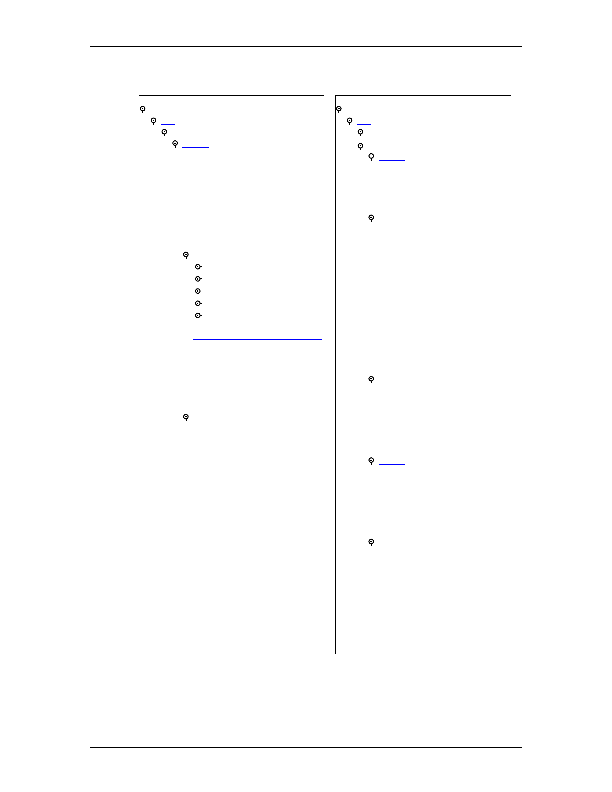
70 Configuring Enterprise Edge Resources
Note: Depending on which Media Bay Module your system is equipped with, the
settings and parameters available may vary.
Media Bay Modules
Bus 02 - 07
Modules on Bus
1
Module
Module type PRI
Low line/loop
High line/loop
Protocol
Protocol type
NSF extension
B channel selection sequence
Clock source
Overlap receiving
Call-by-call service selection
Foreign Exchange
Inwats (800)
Switched Digital (SDS )
Inter...
Nine Hundred (900)
T1 Parameters (North America only)
CO fail
Interface levels
Framing
Internal CSU
CSU line build
Line coding
Provision lines
Line xxx
Status
Media Bay Modules (cont’d)
02 - 07
Bus
Modules on B us
Ports on Bus
Module 1
Module type Loop
Low line/loop
High line/loop
Disconnect timer
1
Module
Module type T1
Low line/loop
High line/loop
Disconnect timer
Answer timer
Clock source
T1 Parameters (North America only)
CO fail
Interface levels
Framing
Internal CSU
CSU line build
Line coding
1
Module
Module type BRI-ST
Low line/loop
High line/loop
Protocol
Clock Source
Overlap receiving
1
Module
Module type DPNSS
Low line/loop
High line/loop
Clock source
Local num len
Maximum transits
1
Module
Module type DASS2
Low line/loop
High line/loop
Clock source
Enterprise Edge 2.0 Programming Operations Guide P0911588 Issue 01
Page 71

Configuring Enterprise Edge Resources 71
To enable or disable any o f the buses on the Enterprise Edge system:
1. Under the Resources heading, click the Media Bay Modules key.
Buses02to08aredisplayed.
2. Select the bus you wish to disable.
Information about the bus is displayed and the Configuration menu option is
enabled.
3. On the Configuration menu, select Disable.
The system prompts you to confirm your request.
4. Click the OK button to disable the bus.
Bus
Bus 01 is reserved for the MSC card. Because there is no hardware programming
required for the MSC card, bus 01 is not displayed. You can view and perform
maintenance operations on Bus 01.For more information, seeMaintenance on page
259.
For a detailed description of the various Media Bay Modules and proper hardware
configurations, see the Enterprise Edge Installation and Maintenance Guide.
Note: Because the voice over IP (VoIP) functionality resides on the MSC card, it
is not necessary to program any hardware settings for it. The Trunk mode
isautomaticallysettoVoIPfor lines 001 to 014. For more information, refer
to Lines on page 108.
To configure a bus type:
1. Choose Resources, Media Bay Modules.
2. Click a Bus (Bus 02 to 07).
Note: Bus 08 is reserved for configuring a data module, which provides a
soft router connection to a remote router. The functionality for this
feature is on the Media Services Card, not in a discrete media bay
module. For information about programming a data module, see
Configuring a data module on page 79.
3. From the Programmed Bus Type list, choose a bus type.
P0911588 Issue 01 Enterprise Edge 2.0 Programming Operations Guide
Page 72

72 Configuring Enterprise Edge Resources
4. Press Enter.
The choice of Programmed Bus Type available depends on the hardware unit
that is installed. The following table shows the type of bus available for each
hardware unit.
Bus Type Hardware unit
Station module Digital Station Media Bay Module (EE-DSM 16 or
Analog station module Analog Station Media Bay Module (EE-ASM 8)
Trunk module Digital Trunk Media Bay Module (EE-DTM)
Fiber Expansion Module Set module, Analog Station Module, UK analog LEC,
Module
The Module heading lets you configure settings for the module. Options displayed
depend on the type of Media Bay Module installed in your system and the Module
type you select.
EE-DSM32)
CLID Trunk Media Bay Module (EE-CTM)
BRI S/T Media Bay Module ( EE-BRIM S/T)
BRI-U2, BRI-U4, BRI-ST
To program a module:
1. Choose Resources, Media Bay Modules, Bus 02-07, Ports on Bus and
Module 1 to access the module configuration settings.
2. Click a Module type: Loop, PRI, BRI-ST, DASS2, DPNSS or T1, and press
Enter.
Note: To provision PRI lines, see Provision lines on page 81.
3. Configure the card settings according to the following table:
Attribute Description
Low/line loop Automatically assigned based on the card type and the module number.
For more information, see page 73
Values: View only
High line loop Automatically assigned based on the card type and the module number.
For more information, see page 73
Values: View only
1
Disconnect timer
Answer timer
Lets you specify the duration of an Open Switch Interval (OSI). For
more information, see page 74
Values: 60, 100, 260, 460, or 600 milliseconds (Default: 460)
2
Lets you set the minimum duration of an answer signal before a call is
considered to be answered.
Values:1,2,3,4,or5seconds(Default:2)
.
.
.
Enterprise Edge 2.0 Programming Operations Guide P0911588 Issue 01
Page 73

Attribute Description
Protocol
Protocol type
NSF Extension
3
Lets you define a trunk protocol. For more information, see page 74.
Values: NI-2, DMS100, DMS250, AT&T4ESS, SL-1, Euro, Q-Sig
3
Lets you define a protocol type. This settings applies to the SL-1 private
networking protocol only. For more information, see page 74
Values: User (Slave), Network (Master)
Default: User (Slave)
3
Lets you define the Network Specific Facilities (NSF) information
element. If the prompt Clear Routes is displayed, click Yes to confirm
your selection. For more information, see page 74
Values: None, WATS, ALL
Configuring Enterprise Edge Resources 73
.
.
B-channel
selection
sequence
Clock Source
3
Notes:
1 Applies to Loop and T1 card types only.
2 Applies to T1 card types only.
3 Applies to PRI card types only, NI2 protocol only.
4 Applies to PRI and T1 card types only.
Lets you define how B-channels are selected. For more information, see
page 75
Values: Ascending Sequential, Descending Sequential
4
Lets you designate which EE-DTM acts as a primary or secondary
timing slave or a Timing Master. The Clock Source may also be
programmed on BRI T-loops or NT loops. For more information, see
page 75
Values: Primary, Secondary, Timing Master
.
.
Note: There must be an EE-DTM installed if you want to program PRI or T1 trunk
lines. The EE-DTM is automatically disabled and re-enabled when you
change the card type. There is no need to manually enable and disable it.
Low line/loop High line/loop
Low line/loop and High line/loop settings are automatically assigned according to
the settings in the following table. Note that Buses 6 and 7 are reserved for the
Companion mobility option if Companion is included in the system.
Card Type Bus 02 Bus 03 Bus 04 Bus 05 Bus 06 Bus 07
T1 (Card 1) 211-234 181-204 151-174 121-144 91-114 61-84
PRI (Card 1) 211-233 181-203 151-173 121-143 91-113 61-83
Loop (Card 1) 211-214 181-184 151-154 121-124 91-94 61-64
Loop (Card 2) 219-222 189-192 159-162 129-132 99-102 69-72
Loop (Card 3) 227-230 197-200 167-170 137-140 107-110 77-80
Loop (Card 4) 235-238 205-208 175-178 145-148 115-118 85-88
Note: PRI on a T1 carrier has 23 lines (for example, Bus 2 has L211-233). PRI on
an E1 carrier has 30 lines (for example, Bus 2 has L211-l240).
P0911588 Issue 01 Enterprise Edge 2.0 Programming Operations Guide
Page 74

74 Configuring Enterprise Edge Resources
Disconnect timer
Disconnect timer (North America only) lets you specify the duration of an Open
Switch Interval (OSI) before a call on a supervised external line is considered
disconnected. This setting must match the setting for the line at the central office
(CO).
You must enable disconnect supervision by changing the Trunk mode attribute.
Under the Telephony Services sub-heading, choose Lines and Line/trunk Data. See
Trunk/line data on page 111 for more information.
Protocol
Enterprise Edge supports a number of different trunk protocols used by different
service providers and markets. Supported protocols are listed in the table below.
ISDN Service Protocol
PRI-T1 NI-2, DMS100, DMS250, AT&T4ESS, SL-1
PRI-E1 QSIG, Euro, Sl-1
BRI (North America) NI
BRI (Europe) Euro, QSIG
Protocol type
When you select SL-1 protocol, an additional setting, Protocol type, appears.
Because SL-1 protocol is a private networking protocol, you have the option of
designating an Enterprise Edge node as a Network (Master). The default setting is
User (Slave). In public network configurations, the CO is generally considered the
Network side or Master.
Protocol Type
NI-2, DMS100, DMS250, AT&T4ESS Public protocols
SL-1 (premium feature) Private protocol
NSF Extension
If you select the NI-2 protocol and you are using Call-by-Call services, you must
specify how Enterprise Edge should handle the NSF (Network Specific Facilities)
The table below summarizes the NSF Extension settings recommended for each
switch type.
Central Office NSF Extension Setting
DMS100 None
Siemens ESWD, Lucent 5ESS WATS
GTD5, DMS10 ALL
The Network Specific Facilities (NSF) information element is used to request a
particular service from the network.
When you select NONE, the NSF extension bit is not set for any service.
When you select WATS, the NSF extension bit is set for unbanded OUTWATS calls.
When you select ALL, the NSF extension is always set for all CbC services.
Enterprise Edge 2.0 Programming Operations Guide P0911588 Issue 01
Page 75

Configuring Enterprise Edge Resources 75
B-channel selection sequence
B-channel selection sequence lets you select either Ascending Sequential or
Descending Sequential depending on your service provider. You should choose
the opposite setting of your service provider.
If all lines for two EE-DTMs (configured as PRI) are in the same PRI pool, then
both cards must be set to use the descending B-channel selection sequence. As a
result, the service provider must use ascending sequential sequence.
The B-channel selection sequence for BRI QSIG is always set to Descending on
Enterprise Edge, so it must set to Ascending on the service provider.
Clock Source
Clock Source lets you designate which of the systems’ Digital Trunk Modules
(EE-DTMs) obtains the timing reference from the network to be used for
synchronization.
Systems with digital interfaces need to synchronize to the network in order to
function. Synchronization is done ina hierarchical way,where each device (switch)
obtains the network clock from the device above it in the synchronization hierarchy
and passes the network clock to the device below it in the synchronization
hierarchy. The synchronization levels are referred to as strata. BRI modules can
also be used for the timing reference.
Enterprise Edge systems are stratum 4E equipment and are usually used as
termination points in a network.
For each EE-DTM, choose one of the following settings: Primary, Secondary,or
Timing Master.
Primary reference
The EE-DTM obtains the timing reference from the network and the system
synchronizestoit. This is the default value for the first EE-DTM in Enterprise Edge.
If the system is configured with an EE-DTM (configured as PRI), the setting should
be set to Primary.
Secondary reference
The EE-DTM acts as a standby reference. If there are excessive errors on the
primary T1 reference link, or the EE-DTM designated as primary reference fails,
the second EE-DTM will obtain the timing reference from the network to be used
for system synchronization. This is the default value for the second EE-DTM in
Enterprise Edge.
P0911588 Issue 01 Enterprise Edge 2.0 Programming Operations Guide
Page 76

76 Configuring Enterprise Edge Resources
Timing Master
The EE-DTM does not obtain timing from the network, but transmits the systems
timing to equipment connected to it.
Changing clock source may disconnect calls.
Changing the clock source for your system may cause your system to restart
itself, resulting in dropped calls. Choose a suitable time to change the clock
source and use the Page feature to inform users of possible service disruptions.
Tips
In most T1 network configurations, you need one EE-DTM configured as PRI
to act as a primary reference. The only application where you might not have a
PRI EE-DTM designated as a primary reference is in a network where your
Enterprise Edge system is connected back-to-back with another switch using a
T1 link or PRI link. If the other switch is loop-timed to your Enterprise Edge
system, your EE-DTM configured as PRI can be designated as a timing master.
If your Enterprise Edge system has two EE-DTMs, you cannot assign both
EE-DTMs as primary reference or both EE-DTMs as secondary reference.
You can only have one primary reference and one secondary reference per
system. You can have a T1 or PRI(T1) or PRI(E1) or BRI as clock source.
Call-by-call service selection
By default, incoming calls are routed based on the Called Party Number. The last
‘N’ digits of the called party numberare usedas ReceivedDigitsto find a target line
(where ‘N’ is the Received Number Length).
For example, the incoming calling party number is 800-555-1234. The received
digit number length is 4, and the result is 1234. These last four digits are used to
route the call.
Depending on the protocol and the service, alternate routing maps may be defined.
1. To change the incoming call routing for a service, select a different service
under Protocol:, Call by Call Routing, FX:
The first applicable service for the given protocol is displayed. In this
example, the service is FX.
Enterprise Edge 2.0 Programming Operations Guide P0911588 Issue 01
Page 77

Configuring Enterprise Edge Resources 77
2. Change the mapping that is applied to incoming calls of this service type to
obtain the received digits. In all cases, the received digits are used to find a
target line or to activate Remote Access.
None: No mapping is applied. The last ‘N’ digits of the Called Party Number
are used as received digits. Note that if there is no called party number (may
occur with some FX calls) the call will ring at the incoming trunk’s Prime set.
All: Lets you define the received digits used for all calls with this service
type, regardless of the called party number or service identifier (SID). For this
option, all calls with this service type on this PRI will ring the same target
line.
Map table: Lets you associate different received digits with different calls of
this service type depending on the call party number and/or the service
identifier. Incoming calls that do not match any entry defined in the map table
will ring at the prime set. Depending on the service type and the protocol, you
may be able to map the called party number (By number) and the service
identifier (SID). The following table shows the different options.
Service
Protocol FX 800 I-800 SDS 900
NI-2 SID By number N/A N/A N/A
DMS-100 SID SID or By number N/A N/A N/A
DMS-250 SID SIDor By number N/A N/A SIDor By number
4ESS N/A Bynumber Bynumber Bynumber Bynumber
Note: This setting is available for T1 trunks configured as T1 E&M. See Trunk/
line data on page 111 for more information about configuring trunk types.
T1 Parameters (North America only)
The T1 Parameters heading appears for card types that have been configured as T1
or PRI. It lets you define a number of settings that are dependent on your T1 service
provider settings.
To program T1 Parameters:
1. Choose Resources, Media Bay Modules, Bus 02-07, Modules on Bus,
Module 1,andT1 Parameters.
P0911588 Issue 01 Enterprise Edge 2.0 Programming Operations Guide
Page 78

78 Configuring Enterprise Edge Resources
2. Configure the T1 parameters according to the following table:
Attribute Description
CO fail Lets you select the carrier failure standard used by your T1 or PRI
service provider. Consult your T1 or PRI service provider for the proper
setting.
Values: TIA-547A or TR62411 (Default: TIA-547A)
Interface levels Lets you define a loss plan setting. For more information, see page 78
Values: ISDN or PSTN (Default: ISDN)
Framing Lets you select the framing format used by your T1 or PRI service
provider: Extended Superframe (ESF) or Superframe (SF). Contact your
T1 or PRI service provider for the proper setting. ( SF or Superframe is
sometimes known as D4.)
Values: ESF or SF (Default: ESF)
Internal CSU Lets you turn the internal T1 channel service unit on or off. For more
information, see page 79
Values: On or Off (Default: On)
CSU line build Lets you set the gain level of the transmitted signal. This setting only
appears when the Internal CSU is set to On.
Values: 0, 7.5, or 15 dB (Default: 0)
DSX1 build Lets you set the distance between Enterprise Edge and an external
channel service unit. This setting only appears when the Internal CSU is
set to Off. Contact your service provider for the proper settings.
Values: 000-100, 100-200, 200-300, 300-400, 400-500, 500-600, or
600-700 feet (Default: 000-100)
Line coding Lets you define the encoding signals on a T1 line. Select the standard
used by your T1 service provider. Contact your T1 service provider for
the proper setting.
Values: B8ZS or AMI (Default: B8ZS)
.
.
Interface levels
Interface levels defaults to the ISDN loss plan setting.
Find out if your Enterprise Edge system is connected to a central office (CO) with
digital network loss treatment (ISDN I/F levels) or analog network loss treatment
(PSTN I/F levels) by checking with your telecommunications service provider.
The ISDN setting requires digital access lines (DAL) that have digital network loss
treatment. On a DAL network, it is the PBX, rather than the CO, that administers
the dB loss. DALs may have ISDN signaling or digital (such as T1 and so on)
signaling. The loss plan follows the Draft TIA-464-C loss plan, which uses a send
loudness rating (SLR) of 8 dB. To have DAL network loss treatment on a line with
digital signaling, you must contact your service provider.
The PSTN setting requires analog access lines (AAL) thathave analog network loss
treatment and digital signaling. On an AAL(D) network, the CO administers the dB
loss.
Enterprise Edge 2.0 Programming Operations Guide P0911588 Issue 01
Page 79

Configuring Enterprise Edge Resources 79
The loss plan follows the Draft TIA-464-C loss plan. The ISDN loss plan uses a
send loudness rating (SLR) of 8 dB and a receive loudness rating (RLR) of 2 dB.
The PSTN loss plan uses an SLR of 11 dB and an RLR of -3 dB. Choosing the
wrong setting may affect voice quality, either too loud or too soft.
Internal CSU
Internal CSU lets you turn the internal T1 channel service unit on or off. The
channel service unit gathers performance statistics for your T1 lines or PRI with
public interface. Contact your service provider for the proper settings.
Note: You must disable the EE-DTM before you can change this setting. See
Media Bay Module status on page 279 for details.
You can view the performance statistics for your T1 lines in Maintenance under the
CSU stats heading. If you set the internal CSU off, there must be an external CSU
connected to your T1 lines.
E1 Parameters (Europe)
Enterprise Edge does not provide E1 parameters. If your Enterprise Edge is
connecting to a network using E1 trunks, make sure CRC4 checking is enabled at
the other end.
Configuring a data module
Module08 is reserved for a datamodule. The data module provides connectivityfor
a soft router through Enterprise Edge from facilities such as T1 and BRI. The
remote soft router server only needs to be powered up and running for the feature
tobe available. Enterprise Edge automaticallyconfigures the Module type asa Data
Module, sets the Data module type to Baystack, and sets the IP address. Baystack
is currently the only soft router supported on Enterprise Edge.
Viewing the data module settings
Use the following procedure to view the current settings for the data module.
1. Under Resources, Media Bay Modules, choose Bus 08.
Note: Before you can configure the data module for fixed access, you must first
configure an EE-DTM module as T1(see Module on page 72) and you must
set the trunk type to Fixed data channel (see Trunk/line data on page 111).
Programming the BayStack settings
When you select the BayStack data module, the following configuration settings
appear:
• IP address
• Switched access
• Line assignment
P0911588 Issue 01 Enterprise Edge 2.0 Programming Operations Guide
Page 80

80 Configuring Enterprise Edge Resources
• Line pool access
• Fixed access
IP address
This is the IP Address of the BayStack data module.
Switched access (PRI & BRI)
You can assign ISDN lines to the BayStack data module to provide:
• normal data network access for the data module
• dial-up backup and overflow bandwidth (additional channels or trunks) as
needed
The line assignment and line pool access settings are displayed in Switched access.
Line assignment
Use the following procedure to assign one or more lines to the BayStack data
module for incoming data transmission:
1. In Line Assignment, enter the number of the trunk or a target line you need to
assign to the BayStack data module.
The status of the line appears as assigned to the current data module,
unassigned, or assigned to another data module. You can assign a trunk
directly to the BayStack data module.
2. Select Unassigned or Assigned.
If the line is assigned to another data module, you can reassign it to the current
data module.
3. Enter the Dial-In Number for the line (up to 24 digits). The number must
match the Dial-In Number entered for the line and channel in BayStack data
module programming.
4. Assign additional lines to the BayStack data module as required.
Line pool access
Use the following procedure to give the BayStack data module access to a line pool
for outgoing data transmission:
1. The settings for access to the line pools are displayed in Line pool access.
Enterprise Edge 2.0 Programming Operations Guide P0911588 Issue 01
Page 81

Configuring Enterprise Edge Resources 81
2. Select the line pools in the list to provide access to the BayStack data module.
You must program line pool access when you select the switched access
settings for the BayStack data module. To use PRI line pools, program the
BayStack data module to use a destination code.
For more information about programming switched access, see the data module
Installer Guide.
Provision lines
The Provision lines heading lets you provision and deprovision ISDN lines. It also
lets you disable PRI channels.
Provision a T1 line
1. Choose Resources, Media Bay Modules.
The window displays Buses 02 through 08.
2. Choose the bus (Bus 02 to 07) associated with the module you want to
provision.
Note: Bus 08 is reserved for a data module and has no lines to provision.
3. Expand the Modules on Bus heading.
The modules on this bus are displayed.
4. Choose the module (for example, Module 1) you want to provision.
5. Expand Provision lines.
All the available lines are displayed.
6. Click the line you want to provision.
7. From the Status box, click Provisioned.
Provision a PRI or BRI line
PRI lines are provisioned by default. BRI loops/lines are provisioned by default
only in the international markets.
Deprovision a line
Deprovisioning all of the lines on an EE-DTM does not disable the module.
Note: BRI loops/lines are deprovisioned by default in the North American market.
P0911588 Issue 01 Enterprise Edge 2.0 Programming Operations Guide
Page 82

82 Configuring Enterprise Edge Resources
1. Choose Resources, Media Bay Modules.
The window displays Buses 02 through 08.
2. Choose the bus (Bus 02 to 07) associated with the module you want to
provision.
Note: Bus 08 is reserved for a data module and has no lines to provision.
3. Expand the Modules on Bus heading.
The modules on this bus are displayed.
4. Choose the module (for example, Module 1) you want to provision.
5. Expand Provision lines.
All the available lines are displayed.
6. Choose the line you want to deprovision.
7. From the Status box, click Deprovisioned.
Disable a PRI Channel
PRI channels can be disabled; however, there is no association between a line
number and a B-channel. Disabling of a B-channel can be done when you have
fractional PRI. For more information, refer to Link Status on page 301.
Enterprise Edge 2.0 Programming Operations Guide P0911588 Issue 01
Page 83

Configuring Enterprise Edge Services
This chapter describes the programming procedures for the many Enterprise Edge
Services, from Telephony to Firewall Filters. Note that a number of other
programming steps are also required to get the system up and running.
Programming order
Program Enterprise Edge system components in the following order to ensure
optimum operation:
1. Media Bay Modules (hardware); see Media Bay Modules on page 69.
2. Lines; see Lines on page 108
3. Terminals & sets; see Terminals & sets on page 90
4. General Settings; see General on page 91
5
5. Companion (N.A. only), Hunt Groups, Hospitality; see Companion on page
177, Hunt groups on page 170, Hospitality on page 183
6. System Speed Dial and Telco Features; see System speed dial on page 145,
Telco features on page 187
7. Passwords; see COS Passwords on page 160
Programming affects system operation.
Only a qualified system administrator should perform startup, installation and
maintenance programming. Many of the setti ngs affect correct system operation.
P0911588 Issue 01 Enterprise Edge 2.0 Programming Operations Guide
Page 84

84 Configuring Enterprise Edge Services
Programming Services
This is the Services programming map:
Services
Telephony Services
Terminals & Sets
Lines
Loops
Restriction filters
Time & date
Call Routing
Scheduled Services
System speed dial
General settings
Hunt groups
Companion
Hospitality
Telco features
Voice Mail
Call Detail Recording
Report Params
Report Options
MarketParams
Prefix Bins
Access Bin Settings
TAPI
TAPI Service Provider
TAPI Server Configuration
Console Service
Server Configuration
General Information
Diagnostic Logging
VoIP Gateway
H323 Gateway
Remote Gateway
DHCP
LAN1
LAN2
DNS
IP Routing
LAN1
LAN2
V90-1(ModemBackup)
V90-2(TivDialup)
IPX Routing
LAN1
LAN2
V90-1(ModemBackup)
V90-2(TivDialup)
SNMP
QoS
Filters
PortRanges
QoS monitor
Mean Opinion Score
Web cache
Net Link Manager
Alarm Service
NAT (Network Address
Translation))
LAN1
LAN2
V90-1(ModemBackup)
V90-2(TivDialup)
IP Firewall Filters
LAN1
LAN2
V90-1(ModemBackup)
V90-2(TivDialup)
You can configure Services attributes under the following headings in the Services
section of Unified Manager:
• Telephony Services on page 87
• Voice Mail on page 188
• Call Detail Recording on page 188
• TAPI on page 188
• Console Service on page 189
• VoIP Gateway on page 189
• DHCP on page 192
• DNS on page 199
• IP Routing on page 200
• IPX Routing on page 208
• SNMP on page 216
• QoS on page 220
• QoS monitor on page 227
Enterprise Edge 2.0 Programming Operations Guide P0911588 Issue 01
Page 85

• Web cache on page 228
• Net Link Manager on page 229
• Alarm Service on page 232
• NAT (Network Address Translation) on page 232
• IP Firewall Filters on page 235
Viewing Enterprise Edge Services
To access Services attributes from Unified Manager:
1. On the menu, click Group, then Services (or click Comprehensive to display
all options).
2. To expand the navigation tree, click the Enterprise Edge key ( ) and
Services. The Enterprise Edge Services table appears, with the name, status,
version, and description of the available services. This table also appears
when you select Enterprise Edge, System.
Configuring Enterprise Edge Services 85
3. Click the Services key to expand the tree. The first listing is Telephony
Services.
Viewing all Services
To view the status, version and description of all Services:
1. ClickontheSystem heading.
The Item, Resources and Services screens appear.
To Enable or Disable a Service
2. On the Configuration menu click Modify Services.
The Services dialog box appears.
3. Click Enabled or Disabled in the Status box.
4. Click Save.
P0911588 Issue 01 Enterprise Edge 2.0 Programming Operations Guide
Page 86

86 Configuring Enterprise Edge Services
Statuses
Status Description
Enabled Indicates that the resource or service is currently operating. When the
component is enabled, the component can assume any of its operational
statuses.
Disabled The component is disabled from operation. None of the component’s
operational statuses are valid in this state.
Paused The component is enabled and is running b ut is currently not accepting
additional service requests.
Up This value is read-only. It indicates that the component is enabled and is
operating normally. For a component like a network interface, this means
the interface is enabled and connected to a valid link. For a service like
DHCP, it means that the service is enabled and is currently running
normally
When the current status is Up, setting it to Enabled or Continue (where
available), is a no-operation. Setting it to Disabled disables the service, by
shutting it down and then disabling it. Where avai lable, setting it to Paused
pauses the service
Down This value is read-only. This value indicates that the user has enabled the
component, and the component is unable to operate in an Up state because
of normal or abnormal, internal or external errors. For example, if a network
interface is in a Down state because of no connection to an actual physical
link, it is a normal, external error. If a service like DHCP service is in a
Down state because of internal errors, it is an abnormal, internal error.
When the current status is Down setting it to Enabled attempts to bring it to
'Up' state again. In an error still exists it may stay at a Down state. Setting it
to Disabled disables the service. Where available, setting it to a Paused or
continued state fail as the service is not yet running.
Enabled This value is write-only. This value never appears when read. For a service
that is enabled, one of its operational statuses (that is, Up or Down) appears
when its Status field is read.
When this value is set, it indicates that the user wants to enable the
corresponding component and bring it to an Up state. It is probable that the
first happens. The second action depends on the component. For a network
interface, the Up state does not happen unless user connects a link to the
interface. For a service this may not happen only if the system encounters
an error of some kind during the requested action.
Disabled This value can be either read or set. When read, this indicates that the
component is di sabled from operation. When set, it indicates the same, in
addition to taking the component to a Down state before disabling.
Paused This value can be either read or set. When read, this indicates that the
service is enabled and is given the command to pause. When set, it indicates
the same, pausing the service further.
Continue This value can only be set. It can be set only when the service in a Paused
state. It resumes paused service.
Enterprise Edge 2.0 Programming Operations Guide P0911588 Issue 01
Page 87

Te le ph on y S er v i ce s
This section describes the procedures to configure Enterprise Edge Telephony
Services, found under the Services heading in Unified Manager.
Telephony Services allows you to program and manage all the voice components
associated with Enterprise Edge. You can set up lines and trunks, define settingsfor
individual telephones, and customize your telephone network to suit your
requirements. From Unified Manager, expand Services and Telephony Services to
view the subheadings.
The table below summarizes the Telephony Services subheadings. Note that
provisioning and diagnostics information is in Maintenance on page 259.
Note: To jumpto any section for more information,click the blue, underlined text.
The information is automatically displayed.
Configuring Enterprise Edge Services 87
Terminals & sets
Lines
Loops
Restriction filters
Time & date
Call Routing
Scheduled Services
System speed dial
General Settings
Hunt groups
Companion Allows you to assign settings for portable telephones.
Hospitality
Telco features
Allows you to assign settings to each telephone.
Allows you to assign settings to each trunk and target line.
Allows you to configure settings for BRI loops.
Allows you to apply restriction filters for external calls.
Allows you to set the display format for both date and time.
Allows you to define how calls are routed on your Enterprise Edge
system.
Allows you to create services, such as night ringing, routing and
restrictions, for making external calls.
Allows you to create speed dial codes that can be used by any
telephone in the system.
Allows you to change system-wide settings.
Allows you to create a nd manage hunt groups.
Allows you to assign Hospitality settings.
Allows you to assign settings for external voice message services.
When you select Telephony Services,theTools menu becomes active. The Tools
menu allows you access to the Backup and Restore tool. For more information on
using the Backup and Restore tool, refer to Backup and restore on page 260.
P0911588 Issue 01 Enterprise Edge 2.0 Programming Operations Guide
Page 88

88 Configuring Enterprise Edge Services
The following illustration shows an overview of the Telephony Services
programming that is accessible through Unified Manager.
Telephony Services
Terminals & sets
DN 221-528
General
Line access
Capabilities
User preferences
Restrictions
Telco features
Lines
Line 001-364
General
Trunk/line data
Restrictions
Line restrictions
Remote restrictions
Module 1
Loops
Loop nnn
SPIDs
Restriction filters
Filter 00-99
Restrictions
Overrides
Time & date
Call Routing
Routes
Route 000-xxx
Destination codes
Scheduled Services
Ringing service
Ring groups
Schedules
Restriction service
Routing Service
Common Settings
Schedule names
Schedule times
System speed dial
Speed dial # 01-70
General Settings
Feature settings
Call log space
Timers
Direct dial
Set 1-5
CAP assignment
CAP 1-5
Dialing plan
Private network
Public network
Access codes
Line pool codes
Carrier codes
Remote access packages
Package 00-15
COS Passwords
COS 00-99
DN lengths
CbC limits
Pool
Release reasons
Network Services
ETSI
Hunt groups
Hunt group 01-30
Members
Line assignment
Companion
Registration
Radio data
Hospitality
Set/room settings
Call permissions
Alarm data
Telco features
Voice message c enter numbers
Outgoing name and number
blocking (ONN)
Enterprise Edge 2.0 Programming Operations Guide P0911588 Issue 01
Page 89

Configuring Enterprise Edge Services 89
Enhanced 911 (E911) Configuration
Government rules vary for support of Enhanced 911 (E911) dialing service by
Customer Premises Equipment. Legislation may require that the Customer
Premises Equipment give a more precise location of the source of a 911 call than
the billing address of the central office line. Consult your service provider about the
laws and regulations.
Use the following configuration rules when installing the Enterprise Edge system,
to assure compliance with local regulations:
• When equipped with PRI trunks, Enterprise Edge can deliver the Calling Line
ID of a telephone dialing 911 through the Public Switched Telephone Network,
if the proper programming has been implemented and PRI trunk service has
been installed by the service provider. If you are using ISDN PRI, implement
OLI programming and Business Name programming to add the Set ID to the
CLASS information.
• By default, Restriction Filter 02 is assigned to all sets on startup. There are no
restrictions applied in Restriction Filters 02-99. Restriction Filter 01 has
restrictions, but 911 is an Exception for this filter. For information on how to
change the Restrictions, refer to Restrictions on page 103.
• When using other trunk interfaces, you can assign separate line pools to groups
of telephones in different areas (for example, in different buildings, floors or
sections).
• Be careful when using the Set Relocation feature. You may have to reprogram
the line pool access to send the right location on 911 calls.
• Configure the 911 destination code to dial out over a Normal Schedule in all
applicable Service Modes, as this is the default route should any other
programmed routing attempts fail. When using PRI interfaces, make sure all
sets can use the PRI line pool that the Normal Schedule route uses.
P0911588 Issue 01 Enterprise Edge 2.0 Programming Operations Guide
Page 90

90 Configuring Enterprise Edge Services
Terminals & sets
The Terminals & sets heading allows you to assign settings to each telephone. The
following shows a detailed view of the Terminals & sets navigation tree.
Terminals & sets
DN 221-528
General
Name
DN type
Control set
Call log passwords
Line access
Prime line
Intercom keys
OLI number
Line assignment
(Line 001)
Appearance type
Call log set
Vmsg set
Line pool access
Pool A
Answer DNs
Capabilities
DND on busy
Handsfree
HF answerback
Pickup group
Page zone
Paging
Direct dial
Priority call
Aux ringer
Allow redirect
Redirect ring
Call forward
Fwd no answer to
Fwd no answer delay
Fwd on busy to
Hotline
Type
ATA settings
ATA answer timer
ATA use
Msg indicate
Terminals & sets (cont’d)
User preferences
Model
Call log options
Dialing options
Language
Contrast
Ring type
Button programming
User speed dial
Restrictions
Set restrictions
Set lock
Allow last number
Allow saved number
Allow link
Schedules
Line/set restrictions
Telco features
First display
Auto called ID
Set log space
Available log space
Enterprise Edge 2.0 Programming Operations Guide P0911588 Issue 01
Page 91

Configuring Enterprise Edge Services 91
Copying settings from one telephone set to another
The Copy command allows you to duplicate programming for a telephone and
apply it to another telephone, a range of telephones or all the telephones on the
system.
To copy telephone settings:
1. Choose Services, Telephony Services, Terminals & sets.
2. Click the telephone set (DN 221-528) with the settings you want to copy.
If necessary, choose a subheading to refine your selection.
3. On the Edit menu, click Copy.
4. Choose the data type you want to copy, System data or System+user data.
5. Click Single, Range or All from the Copy type list.
6. Type the DN number of the set or the range of sets (nnn-nnn) where you want
to copy the settings. You do not have to fill in this box if you chose All in the
Copy type list.
7. Click the OK button.
General
The General attributes allows you to assign the name, the DN type, a control set,
and the Call log password for a set.
Name
The default name for a telephone is its DN. You can change it to a more descriptive
name.
To assign a name to a telephone:
1. Choose Services, Telephony Services, Terminals & sets.
2. Click the telephone set (DN 221-528).
3. Click General.
4. In the Name box, type a name up to seven characters, and then press Enter.
Note: The name can be a combination of letters and numbers.
P0911588 Issue 01 Enterprise Edge 2.0 Programming Operations Guide
Page 92

92 Configuring Enterprise Edge Services
DN type
The DN type attribute allows you to choose the set type: ISDN set or portable set.
For Enterprise Edge desk sets, you can view but you cannot change the DN type.
To change the DN type:
1. Choose Services, Telephony Services, Terminals & sets.
2. Click the telephone set (DN 221-528).
3. Click the General heading.
4. Click a DN type: ISDN or Portable.
Note: In North America, DNs 469 to 500 are Portable sets and DNs 501 to
528 are ISDN sets by default.
Control set
The Control set attribute allows you to define a DN that will act as a control set. By
default, DN 221 is the control set for all telephone sets (DNs). A control set can turn
Scheduled Services, such as Restriction Service on and off for the telephones
assigned to it. For more information about services, see Scheduled Services on page
138.
You can assign several control sets for your system but you can only assign one
control set per DN.
Tips
You must program external lines and telephones with a control set to use the
three kinds of Scheduled Services: Ringing, Restriction, and Routing Services.
The recommendation is to have one control set for all lines and a different
control set for all telephones (DNs).
You can turn on a service manually or automatically for all telephones
controlled by a given control set, but you cannot combine schedules. In other
words, a service can only be active as normal service or one of the six
schedules at any one time. You can have several schedules active, as long as
they are using different services.
To assign a control set to a DN:
1. Choose Services, Telephony Services, Terminals & sets.
2. Click the telephone set (DN 221-528).
3. Click General.
4. In the Control set box, type the DN number and press Enter, or click None.
Enterprise Edge 2.0 Programming Operations Guide P0911588 Issue 01
Page 93

Configuring Enterprise Edge Services 93
Call log passwords
Call log passwords setting allows you to clear an individual’s Call log password.
This is useful if someone forgets the password and you need to reset it. Select the
set DN and leave the box blank or enter a new password. The user can then enter a
new password from that DN.
To create or reset a call log password:
1. Choose Services, Telephony Services, Terminals & sets.
2. Click the telephone set (DN 221-528).
3. Click on the General heading.
4. Type a 4-digit password in the Call log passwords box, or leave it blank, and
press Enter.
Line access
Line access allows you to assign lines to individual telephones. To save time, you
can copy the Line access settings to other telephones once you have finished
programming the settings for one telephone.
Note: PRI lines must be set to Auto Answer; they cannot be Manual Answer.
Tips
When you assign line access for BRI loops make sure that the programming
for the two lines on a BRI loop is identical. For example, if line 001 on BRI
loop 201 appears at a DN, line 002 on the same loop should appear at the DN
as well.
In general, you do not assign, auto-answer loop start trunks and auto-answer
BRI trunks to telephones. If assigned, they are for monitoring incoming call
usage, or for making outgoing calls.
To assign a line to a telephone:
1. Choose Services, Telephony Services, Terminals & sets, DN.Clickonthe
Line access heading.
P0911588 Issue 01 Enterprise Edge 2.0 Programming Operations Guide
Page 94

94 Configuring Enterprise Edge Services
2. Configure line access according to the table:
Attribute Description
Prime line You can define the first line that a telephone selects when you make a call
from an Enterprise Edge telephone. PRI pools are not valid selections for a
Prime line.
Note: An assigned prime line is not associated with the assignment of a
prime telephone.
Values:None, Pool (A to O), I/C (intercom), or Line: (Default: None)
Intercom keys
OLI number
You can assign the number of intercom buttons to a telephone. Intercom
buttons provide a telephone with access to internal and external lines, and
line pools. Refer to
Values:0 to 8 (Default: 2)
You can define the digits used for originating line identification number
(OLI). Refer to
Values: up to 24 digits (Default: blank)
Intercom keys on page 94.
OLI number on page 95.
You must assign an external line to the telephone in Line assignment (see Line
assignment on page 95) before you can assign the line as the prime line to the
telephone. You must assign a line pool to the telephone in Line pool access (see
Line pool access on page 97) before you can assign a line pool as the prime line to
the telephone. A target line cannot be a prime line for a telephone because it is
incoming-only.
Note: Do not assign a T1 DID line as the prime line for a telephone. If assigned,
the system treats it as if there is no prime line. The set displays the message
Select a line when you lift the receiver.
When you assign a line pool as a prime line, the system searches automatically for
an idle line in the pool. For more information, see Line type on page 116.
3. Choose the Prime line for this DN (Line 001, Pool A, None, I/C). The default
is I/C.
Intercom keys
The Intercom keys attribute assigns the number of intercom keys. Intercom keys
provide a telephone with access to internal and external lines, and line pools.
When you assign each Intercom key during programming, it automatically appears
on the telephone. The intercom keys appear on the lower-right button, or one key
above if the Handsfree/Mute feature appears on the telephone.
Enterprise Edge 2.0 Programming Operations Guide P0911588 Issue 01
Page 95

Configuring Enterprise Edge Services 95
When you assign the number of Intercom keys:
• A telephone requires two intercom buttons to be able to establish a conference
call with two other Enterprise Edge telephones.
• You require only one intercom button if the button is used to make and receive
internal calls, and to access line pools. You require two intercom keys for a
telephone with several lines assigned to Ring only.
• The M7100 telephone can have up to eight intercom buttons although the
telephone has one programmable button.
4. Choose the number of Intercom keys you want to assign to this DN (0, 1, 2, 3,
4, 5, 6, 7, 8). The default is 2.
OLI number
The originating line identification number (OLI) setting allows you to specify the
number that displays on the telephone you are calling.
Enter the digits used for the originating line identification number (OLI).When you
make an outgoing call on a BRI line, the Call Display information that appears on
the telephone you are calling is usually based on the first Network DN associated
with the line.
If the line has more than one Network DN, you can program a DN to use a Network
DN other than the first one for the outgoing Call Display information. When you
program the alternate Network DN as the ten-digit outgoing line identification
(OLI) number, and you make a call using the line associated with the Network DN,
the OLI number appears on the telephone you are calling.
If an outgoing call is made using a line that is not associated with the Network DN
number used as the OLI number, the network ignores the number; the default Call
Display information (the first or only Network DN associated with the line)
appears.
5. Enter the OLI number in the box. The default is blank. OLI numbers for
North America are ten digits.
Line assignment
The Line assignment setting allows you to assign physical trunks and target lines to
each telephone. You can assign and remove target lines the same as other lines. You
can also assign multiple target lines across a group of sets in a Broadcast ring group.
To assign a trunk or target line to a telephone:
1. Choose Services, Telephony Services, Terminals & sets.
2. Click the telephone set (DN 221-528) that you want to assign to a trunk or
line.
P0911588 Issue 01 Enterprise Edge 2.0 Programming Operations Guide
Page 96

96 Configuring Enterprise Edge Services
3. Choose Line access. Click on the Line assignment heading.
4. Click the Add button above the navigation tree.
5. Type a line number in the Line box.
6. Click the Save button.
7. ClickontheLine nnn you just created.
Appearance type
Select how a call on this line shows at the set.
8. In the DN nnn-Line nnn window, choose the line Appearance type. Ring
only, Appear&Ring,orAppear only. The default is Unassigned.
Note: Enterprise Edge will not support a mixture of Appear only and Ring only
appearances for the same line. If you choose Appear&Ring or Appear
only, you can have as many simultaneous DID calls as there are target line
key appearances. If you choose Ring only, you can have as many
simultaneous DID calls as you have intercom keys.
Call log set
The Call log set attribute allows you to specify if the telephone automatically logs
Call Display information for calls on an external line. The line must appear on that
telephone, but it does not have to be a ringing line.
9. Click Y or N to enable call logging. The default is N.
Vmsg (Voice Message) set
If you subscribe to an external voice message service, you can access that service
through your Enterprise Edge system. The voice message setting controls if the
indicator shows on a telephone for voice message waiting on a particular line. The
line must appear on that telephone.
10. Click Y or N to enable voice m essage waiting indicator. The default is N.
To find out if your voice message service works with Enterprise Edge, or if you
have any problems with your service, contact your voice message service provider.
PRI Lines
Users cannot access PRI lines directly through line appearances or line pools.
To dial outgoing PRI calls use the intercom button and enter a routing code.
When an EE-DTM changes to PRI, the system automatically removes all existing
line appearances for that module.
Enterprise Edge 2.0 Programming Operations Guide P0911588 Issue 01
Page 97

Configuring Enterprise Edge Services 97
The Enterprise Edge Analog Terminal Adapter (ATA 2), BRI S-terminals, or a
portable cannot process more than 2 simultaneous calls.
There is a suggested limit of 4 keys per set. You can program more than 4 keys on
a set by programming less than 4 on other sets. For instance, you might program 20
keys on a receptionist set equipped with a CAP.
Tips
In general, you do not assign auto-answer loop start trunks, auto-answer T1
E&M trunks and T1 DID trunks to telephones. If assigned, they are used for
monitoring incoming call usage, or for making outgoing calls (auto-answer
loop start and T1 E&M trunks).
You cannot assign a line that is private to another telephone.
Each line assigned to appear at a telephone must appear at a button with an
indicator on that telephone. The maximum number of line buttons is 8 f or the
M7208 telephone, 10 for the M7310 telephone, and 24 for the M7324
telephone.
If you set a line to Ring only, incoming calls appear on an intercom button.
A central answering position (CAP), with one or two CAP modules, can
provide extra line buttons if more than 24 lines are assigned to the CAP. The
remaining lines appear at buttons on the CAP module.
The M7100 telephone is an exception; i t has no line buttons and can be
assigned any number of lines. Make sure that lines assigned to an M7100
telephone are assigned to ring; otherwise, you cannot detect incoming calls on
the lines.
Line pool access
The Line pool access setting allows a telephone to access one or more of the fifteen
line pools available (A to O). Six exclusive line pools (PRI-A to PRI-F) are
available for PRI lines. Only three are currently supported.
Only PRI or BRI-QSIG lines can belong to a PRI pool. PRI lines cannot belong to
Line Pools A through O, and all lines on a single EE-DTM (PRI) belong to the same
pool. Lines from multiple EE-DTM (PRI) can belong to the same pool if they are
configured with the same protocol. You can assign PRI lines to pools with the Line
type setting.
To assign a line pool to a telephone:
1. Choose Services, Telephony Services, Terminals & sets.
2. Click the telephone set (DN 221-528).
3. Choose Line access, Line pool access.
4. Click the Add button above the navigation tree.
5. Enter a letter from A to O.
P0911588 Issue 01 Enterprise Edge 2.0 Programming Operations Guide
Page 98

98 Configuring Enterprise Edge Services
6. Click the Save button.
The set can now access any line in that line pool.
Answer DNs
You can program a telephone to provide call alerting and call answering for other
telephones. The DNs of the other telephones are referred to as Answer DNs.
Every Answer DN you assign to the telephone automatically designates an Answer
buttonwith an indicator to the telephone. Label the buttons to identify the telephone
with its name or DN. More than one telephone can have an Answer button for the
same DN.
You can assign a maximum number of eight Answer DNs to a set.
To create an answer DN on a telephone:
1. Choose Services, Telephony Services, Terminals & sets.
2. Click the telephone set (DN 221-528).
3. Choose Line access. Click on the Answer DNs heading.
4. Click the Add button above the navigation tree.
5. Type the Answer DN.
6. Click the Save button.
Answer type
1. Select the newly created Answer DN.
2. Choose the Answer type: Appr&Ring,orAppr only. The default is
Appr&Ring.
Capabilities
The Capabilities settings control how the system interacts with individual
telephones and how they receive calls.
To define telephone capabilities:
1. Choose Services, Telephony Services, Terminals & sets.
2. Click the telephone set (DN 221-528).
3. ClickontheCapabilities heading.
Enterprise Edge 2.0 Programming Operations Guide P0911588 Issue 01
Page 99

Configuring Enterprise Edge Services 99
4. Configure Capabilities settings according to the table:
Attribute Description
DND on busy Defines whether an incoming call rings if you are already on another call.
Values:Y or N (Default: N)
Handsfree Defines whether Handsfree is available to a telephone.
Values:Auto, Standard, None (Default: None)
HF answerback Defines whether you can automatically answer a voice call without lifting
the receiver or pressing the Handsfree/Mute button.
Values:Y or N (Default: Y)
Pickup group Assigns this telephone to a pickup group.
Values:None, 1 to 9 (Default: None)
Page zone Assign this telephone to page zone.
Values:None, 1 to 6 (Default: 1)
Paging Defines whether you can make paging announcements from this
telephone.
Values:Y or N (Default: Y)
Direct dial Defines whether you can call the Direct-dial telephone from this telephone
using the Direct-dial digit.
Values:Set 1 to Set 5, None (Default: Set 1)
Priority call Defines whether this telephone can interrupt calls or override Do Not
Disturb at another telephone.
Values:Y or N (Default: N)
Aux ringer Defines whether an auxiliary ringer (if installed) rings for incoming calls
at this telephone.
Values:Y or N (Default: N)
Allow redirect Defines whether this telephone can redirect its lines.
Values:Y or N (Default: N)
Redirect ring Defines whether the telephone rings briefly when a call on one of its lines
is redirected by the Line Redirection feature (ƒ°›).
Values:Y or N (Default: Y)
Call forward
The Call forward setting allows you to define how unanswered calls are handled or
when the line is busy.
To program call forward:
1. Choose Services, Telephony Services, Terminals & sets.
2. Click the telephone set (DN 221-528).
3. Choose Capabilities, click on the Call forward heading.
P0911588 Issue 01 Enterprise Edge 2.0 Programming Operations Guide
Page 100

100 Configuring Enterprise Edge Services
4. Configure Call Forward according to the table:
Attribute Description
Fwd no answer to You can redirect all incoming calls when this telephone does not answer.
Values: up to 24 digits (Default: blank)
Fwdnoanswer
1
delay
Fwd on busy to You can redirect all incoming calls when this telephone is busy with
Notes:
1 Appears after you have entered a call forward no answer number and pressed
Enter.
You can define the number of rings before the system forwards an
unanswered call.
Values: 2, 3, 4, 6, 10 (Default: 4)
another call.
Values: up to 24 digits (Default: blank)
Hotline
The Hotline setting allows you to define a telephone number that automatically
dials when you lift the receiver or press the Handsfree/Mute button on a set. You
can define an internal or external number.
To define an internal Hotline telephone number:
1. Choose Services, Telephony Services, Terminals & sets.
2. Click the telephone set (DN 221-528).
3. Choose Capabilities.ClickontheHotline heading.
4. Click Internal, and then press Enter.
5. In the Internal # box, choose Direct dial set or DN:, and then type the DN
number (up to 3 digits).
To define an external number as a hotline:
1. Choose Services, Telephony Services, Terminals & sets.
2. Click the telephone set (DN 221-528).
3. Choose Capabilities.ClickontheHotline heading.
4. Click External.
5. In the External # box, type the telephone number (up to 24 digits).
Enterprise Edge 2.0 Programming Operations Guide P0911588 Issue 01
 Loading...