

Page 1

Enterprise Edge Installation and
Maintenance Guide
1-800-4 NORTEL
www.nortelnetworks.com
©1999NortelNetworks
P0908507 Issue 02
Page 2

Page 3
NorthAmericanRegulations
Safety
Enterprise Edge equipment meets all applicable requirements of both the CSA
C22.2 No. 950-95 and UL-1950 Edition 3.
Risk of shock.
Ensure the computer is unplugged from the power socket and that any
telephone or network cables are unplugged before opening the computer.
Read and follow installation instructions carefully.
Only qualified persons should service the system.
The installation and service of this hardware is to be performed only by
service personnel having appropriate training and experience necessary to
be aware of hazards to which they are exposed in performing a task and of
measures to minimize the danger to themselves or other persons.
Electrical shock hazards from the telecommunication network and AC mains
are possible with this equipment. To minimize risk to service personnel and
users, the Enterprise Edge system must be connected to an outlet with a
third-wire ground.
Service personnel must be alert to the possibility of high leakage currents
becoming available on metal system surfaces during power line fault events
near network lines. These leakage c urrents normally safely flow to Protective
Earth ground via the power cord. Therefore, it is mandatory that connection
to an earthed outlet is performed first and removed last when cabling to the
unit. Specifically, operations requiring the unit to be powered down must
have the network connections (central office lines) removed first.
Radio-frequency interference
Equipment generates RF energy.
This equipment generates, uses, and can radiate radio-frequency energy. If
not installed and used in accordance with the installation manual, it may
cause interference to radio communications. It has been tested and found to
comply with the limits for a Class A computing device p ursuant to Part 15 of
the FCC Rules and with ICES.003, CLASS A Canadian EMI Requirements.
Operation of this equipment in a residential area is likely to cause
interference, in which case the user, at his or her own expense, will be
required to take whatever measures may be required to correct the
interference.
P0908507 Issue 02 Enterprise Edge Installation and Maintenance Guide
Page 4
4 North American Regulations
Telecommunication registration
Enterprise Edge equipment meets all applicable requirements of both Industry
Canada CS-03 and US Federal Commission FCC Par t68 and has been registered
under files Industry Canada 332-5980 A and FCC AB6CAN-20705-KFE (key system), AB6CAN-20706-MF-E (hybrid system), and AB6CAN-23740PF-E (PBX system). Connection of the Enterprise Edge telephone system to the
nationwide telecommunications network is made through a standard network
interface jack that you can order from your local telecommunications company.
This type of customer-provided equipment cannot be used on party lines or coin
lines.
Before installing this equipment, users should ensure that it is permissible to be
connected to the facilities of the local telecommunications company. The
equipment must also be installed using an acceptable method of connection. The
customer should be aware that compliance with the above conditions may not
prevent degradation of service in some situations.
Repairs to certified equipment should be made by an authorized Canadian
maintenance facility designated by the supplier. Any repairsor alterations made by
the user to this equipment, or equipment malfunctions, may give the
telecommunications company cause to request the user to disconnect the
equipment. Users should ensure for their own protection that the electrical ground
connections of the power utility, telephone lines and internal metallic water pipe
system, if present, are connected together. This precaution may be particularly
important in rural areas.
Users should not attempt to make such connections themselves, but should
contact the appropriate electric inspection authority, or electrician.
Hearing-aid compatibility
Enterprise Edge telephones are hearing-aid compatible, as defined in Section
68.316 of Part 68 FCC Rules.
Electromagnetic compatibility
Enterprise Edge equipment meets all FCC Part 15,Class A radiated and conducted
emissions requirements.
Enterprise Edge does not exceed the Class A limits for radiated and conducted
emissions from digital apparatus as set out in the Radio Interference Regulations of
Industry Canada.
Enterprise Edge Installation and Maintenance Guide P0908507 Issue 02
Page 5

Telephone company registration
It is usually not necessary to call the telecommunications company with
information on the equipment before connecting the Enterprise Edge system to the
telephone network. If the telecommunications company requires this information,
provide the following:
• telephone number(s) to which the system will be connected
• FCC registration number (on label affixed to Enterprise Edge)
• universal service order code (USOC)
• service order code (SOC)
• facility interface code (FIC)
Use of a music source
In accordance with U.S. Copyright Law, a license may be required from the
AmericanSociety of Composers, Authors andPublishers, or similar organizationif
Radio or TV broadcasts are transmitted through the Music On Hold or Background
Music features of this telecommunication system.
North American Regulations 5
Nortel Networks hereby disclaims any liability arising out of the failure to obtain
such a license.
Rights of the telecommunications company
If the Enterprise Edge system is causing harm to the telephone network, the
telecommunications company may discontinue service temporarily. If possible, the
telecommunications company will notify you in advance. If advance notice is not
practical, the user will be notified as soon as possible. The user will be given the
opportunity to correct the situation and informed of the right to file a complaint to
the FCC.
The telecommunications company may make changes in its facilities, equipment,
operations or procedures that could affect the proper functioning of the system. If
this happens, the telecommunications company will give you advance notice in
order for you to make any necessary modifications to maintain uninterrupted
service.
Repairs
In the event of equipment malfunction, all repairs to certified equipment will be
performed by an authorized supplier.
P0908507 Issue 02 Enterprise Edge Installation and Maintenance Guide
Page 6

6 North American Regulations
Enterprise Edge Installation and Maintenance Guide P0908507 Issue 02
Page 7

Contents
North American Regulations 3
Safety 3
Radio-frequency interference 3
Telecommunication registration 4
Hearing-aid compatibility 4
Electromagnetic compatibility 4
Telephone company registration 5
Use of a music source 5
Rights of the telecommunications company 5
Repairs 5
Chapter 1 How to use this guide 15
Introduction 15
Organization of this guide 15
Symbols used in this guide 16
Enterprise Edge system components 17
Chapter 2 Components of the Enterprise Edge server 19
Hardware components 19
Enterprise Edge server components 19
Enterprise Edge telephony components 20
Enterprise Edge data networking components 21
Connection Ports 23
Enterprise Edge server LEDs 26
Software components 26
Enterprise Edge Integrated Solution software 27
Enterprise Edge Voice Messaging 27
Enterprise Edge Call Center 28
Enterprise Edge VoIP Gateway 28
Enterprise Edge TSP 28
Enterprise Edge Personal Call Manager 29
Enterprise Edge Call Detail Recording 29
Enterprise Edge Attendant Console 29
Enterprise Edge Integrated QoS Routing 29
P0908507 Issue 02 Enterprise Edge Installation and Maintenance Guide
Page 8

8 Contents
Chapter 3 Telephony Hardware Description 31
Media Services Card 31
Connection between the MSC and the media bay modules 31
Connection to optional equipment 32
Station media bay modules 34
16-port Digital Station Media Bay Module (EE-DSM 16) 34
32-port Digital Station Media Bay Module (EE-DSM 32) 35
Analog Station Media Bay Module (EE-ASM 8) 36
Trunk media bay modules 37
Digital Trunk Media Bay Module (EE-DTM) 38
Caller ID Trunk Media Bay Module (EE-CTM) 39
Telephones and adapters 41
M7100 41
M7208 41
M7310 41
M7324 41
M7410 41
Enterprise Edge central answering position (CAP) 42
Enterprise Edge Station Auxiliary Power Supply (SAPS) 42
Enterprise Edge Analog Terminal Adapter 2 (ATA 2) 42
Enterprise Edge Companion 42
Chapter 4 Data Hardware Description 45
Modem card 45
LAN card 45
WAN card 45
How to install the Enterprise Edge system 47
Chapter 5 Installation Overview 49
Chapter 6 How to install the Enterprise Edge server 51
Introduction 51
Before you start 51
Preparation checklist 51
Packaging Checklist 51
Environment Checklist 52
Electrical requirements 52
Internal wiring requirements 53
Enterprise Edge server configurations 53
System equipment and supplies 54
Basic hardware 54
Optional equipment 54
Enterprise Edge Installation and Maintenance Guide P0908507 Issue 02
Page 9

Enterprise Edge Companion equipment 55
Equipment for installing the Enterprise Edge system 55
Cables 55
Install the Enterprise Edge server in a rack 56
Attach the rack mounting bracket to the Enterprise Edge serve r56
Install the Enterprise Edge server in the rack 57
Install the Enterprise Edge server on a table or shelf 58
Chapter 7 Start the Enterprise Edge server 59
Check that the power is o n60
Change the power supply voltage 61
Chapter 8 Install the telephony hardware 63
Task overview 63
Connect the wiring65
Connect trunk media bay module wiring65
Connect station media bay module wiring 67
Install the telephones 72
Install digital and analog telephones 72
Install Companion wireless set s72
Install the emergency telephone 73
Install the Enterprise Edge central answering position (CAP )73
Install the Enterprise Edge Analog Terminal Adapter 2 74
Before Installation 74
Analog transmission parameters 75
Connect the Enterprise Edge ATA 277
Install the Enterprise Edge ATA 2 78
Configuration requirements for Enterprise Edge ATA 2 79
Enterprise Edge ATA 2 data communication 80
Install a Data Communication Device 81
Install other optional equipment 82
Auxiliary ringer (customer supplied) 82
External music source (customer supplied) 83
External paging system (customer supplied) 84
Contents 9
Chapter 9 Install Enterprise Edge Companion Wireless 85
Enterprise Edge Companion Wireless 85
Install Companion 86
Install remote power interconnect 86
Install Base Stations 95
Position a Base Station 95
Install a Base Station 96
Install portable telephones 98
Install external antennas and lightning surge protectors 99
P0908507 Issue 02 Enterprise Edge Installation and Maintenance Guide
Page 10

10 Contents
Install procedures for outdoor antennas and lightning surge protectors
for the United States of America 100
Before you install an outdoor antenna (USA) 101
Install a lightning surge protector (USA) 102
Install proceduresfor outdoor antenna and lightning surge protectors for
Canada 103
Power up the system 108
Chapter 10 Install the Data Networking Hardware 109
Task overview 109
Connect wiring to the LAN card 109
Connect wiring to the WAN card 109
Connect wiring to the modem card 109
Chapter 11 Initializing the Enterprise Edge system 111
Setting the initial parameters using a null modem cable 112
Setting the initial parameters 112
Setting the initial parameters using an Ethernet crossover cable 114
Configuring your computer 114
Connecting the Ethernet crossover cable 115
Enterprise Edge Initialization 115
Programming the Enterprise Edge system 116
Enterprise Edge Software 117
Chapter 12 Enterprise Edge Software 119
Software applications 119
Next step 121
Programming your software 121
Software documentation 123
Chapter 13 Enterprise Edge Unified Manager software 125
Overview 125
Enterprise Edge Unified Manager requirements 126
Computer requirements 126
Browser requirements 126
Shutdown the Enterprise Edge server 127
Restart the Enterprise Edge serve r128
Enterprise Edge Installation and Maintenance Guide P0908507 Issue 02
Page 11

Contents 11
Enterprise Edge server Hardware Upgrades and
Replacements 129
Chapter 14 Prepare the Enterprise Edge server to upgrade or replace a hardware
component 131
Overview 131
Special tool s131
Remove the connections132
Remove the Enterprise Edge server from a rack 133
Remove the cover from the Enterprise Edge server134
Remove the front cover 134
Chapter 15 Replacing memor y135
Overview 135
Replacing memory 135
Chapter 16 Replacing the clock/calendar batter y139
Overview 139
Removing the battery 139
Installing the new battery 140
Chapter 17 Replacing the hard disk 143
Overview 143
Removing the hard disk 143
Installing a new hard disk 145
Chapter 18 Replacing the fan147
Overview 147
Removing the fan 147
Installing a new fan 149
Chapter 19 Replacing the power supply 151
Overview 151
Removing the power supply 151
Installing a new power supply 152
Chapter 20 Replacing the main printed-circuit board 155
Overview 155
Removing the main printed-circuit board 155
Installing a new main printed-circuit board 157
P0908507 Issue 02 Enterprise Edge Installation and Maintenance Guide
Page 12

12 Contents
Enterprise Edge telephony hardware upgrades
and replacements 159
Chapter 21 Upgrading or replacing telephony hardwar e161
Overview 161
Upgrading or replacing? 162
Chapter22 Preparingforanupgrade 163
Module numbers 164
Offset 165
Assigning line numbers and extension numbers 166
Rules for assigning lines and trunks 166
Checking the switch setting on the existing media bay modules 166
Setting the switches on the media bay modules 168
Media bay module switch settings 169
Default switch settings 171
Chapter 23 Replacing the MSC 173
Remove the MSC 173
Install the MSPECs on the new MSC 174
Install the MSC 175
Chapter 24 Replacing the EE-CTM 177
Remove the EE-CTM 177
Set the switches on the new EE-CTM 181
Installing the EE-CTM 182
Chapter 25 Replacing the EE-DTM 185
Remove the EE-DTM 185
Set the switches on the new EE-DTM 189
Installing the EE-DTM 190
Chapter 26 Replacing the EE-DSM 16 193
Remove the EE-DSM 16 193
Set the switches on the new EE-DSM 16 197
Installing the EE-DSM 16 198
Chapter 27 Replacing the EE-DSM 32 201
Remove the EE-DSM 32 201
Set the switches on the new EE-DSM 32 205
Installing the EE-DSM 32 206
Enterprise Edge Installation and Maintenance Guide P0908507 Issue 02
Page 13

Chapter 28 Replacing the EE-ASM 8 209
Remove the EE-ASM 8 209
Set the switches on the new EE-ASM 8 213
Installing the EE-ASM 8 214
Chapter 29 Replacing a telephone 217
Replacing telephones of the same type 217
Replacing telephones of different type s217
Status of the replaced telephone 217
Enterprise Edge data networking hardware
upgrades and replacements 219
Chapter 30 Overview of data networking hardware 221
Contents 13
Chapter 31 Replacing the modem card 223
Remove the modem card 223
Install the modem card 224
Chapter 32 Replacing the LAN card 227
Remove the LAN card 227
Install the LAN card 228
Chapter 33 Replacing the WAN card 231
Remove the WAN car d231
Install the WAN card 232
Troubleshooting and Maintenance 235
Chapter 34 Troubleshooting 237
Determining the cause of the problem 237
Hardware problems 237
The Enterprise Edge server does not function at all 238
Emergency telephone does not function 238
Enterprise Edge ATA 2 does not function 239
Preparing the Enterprise Edge server for trave l240
P0908507 Issue 02 Enterprise Edge Installation and Maintenance Guide
Page 14

14 Contents
Chapter 35 Maintenance 241
Moving telephones 241
Running a Maintenance session to test a dead telephone 241
Appendix A: BIX overview 243
BIX tool 243
Operating the tool in the cut positi on244
Operate the tool in the no cut position245
BIX mount installation 246
BIX cable connection249
BIX label strips 259
Appendix B: Virtual network computing (VNC) 261
Installing the VNC viewer 261
Installing the telnet client 261
Using VNC 262
Starting the VNC application 262
Accessing the Enterprise Edge server desktop 262
Quitting VNC 263
Glossary 265
Index 295
Enterprise Edge Installation and Maintenance Guide P0908507 Issue 02
Page 15

How to use this guide
Introduction
The Enterprise Edge Installation and Maintenance Guide provides technical
information and procedures required by a technician to install the Enterprise Edge
system and perform different replacement and upgrade tasks.Use this guide during
and after an initial installation.
To use this guide, you must:
• be a Nortel Networks installer with Enterprise Edge certification
• know basic Nortel Networks terminology
Organization of this guide
The Enterprise Edge Installation and Maintenance Guide has seven sections that
cover:
Enterprise Edge system components — This section provides an overview and
functional description of Enterprise Edge hardware components.
1
Installing the Enterprise Edge system — This section provides the steps
necessary to install an Enterprise Edge system.
Enterprise Edge software — This section describes the software applications
available on the Enterprise Edge system.
Enterprise Edge server hardware upgrades and replacements — This section
provides the steps necessary for upgrading or replacing different components of the
Enterprise Edge system.
Enterprise Edge telephony hardware upgrades and replacements — This
section provides the steps necessary for upgrading or replacing the telephony
components of the Enterprise Edge system.
Enterprise Edge data networking hardware upgrades and replacements —
This section provides the steps necessary for upgrading or replacing the data
networking components of the Enterprise Edge system.
Troubleshooting and Maintenance — This section provides procedures for
finding and solving problems on the Enterprise Edge system.
P0908507 Issue 02 Enterprise Edge Installation and Maintenance Guide
Page 16
16 How to use this guide
Symbolsusedinthisguide
This guide uses symbols to draw your attention to important information. The
following symbols appear in this guide:
Caution Symbol
Alerts you to conditions where you can damage the equipment.
Danger Symbol
Alerts you to conditions where you can receive an injury.
Electrical Shock Hazard Symbol
Alerts you to conditions where you can get an electrical shock.
Warning Symbol
Alerts you to conditions where you can cause the system to fail or work
improperly.
Tip Symbol
Alerts you to additional information that can help you perform a task.
Note: A Note alerts you to important information.
Alerts you to ground yourself before performing the maintenance
procedure.
Alerts you to remove the Enterprise Edge server power cord from the AC
outlet before performing the maintenance procedure.
Enterprise Edge Installation and Maintenance Guide P0908507 Issue 02
Page 17

Section I - Enterprise Edge
system components
• Components of the Enterprise Edge server
• Telephony Hardware Description
• Data Hardware Description
P0908507 Issue 02 Enterprise Edge Installation and Maintenance Guide
Page 18

18 Enterprise Edge system components
Enterprise Edge Installation and Maintenance Guide P0908507 Issue 02
Page 19
Components of the Enterprise Edge server
The Enterprise Edge system includes software and hardware components that
provide normal telephony technology, voice messaging, IP telephony and data
networking.
Note: Some of the components described inthis document are not available in all
areas. Consult with your Nortel Networks Enterprise Edge dealer for
information about the availability of components.
Hardware components
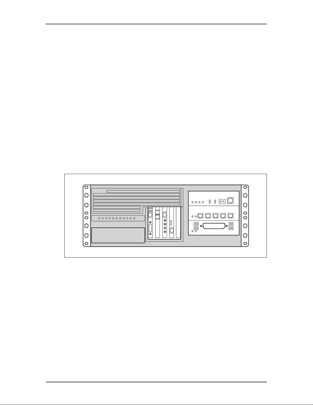
The main component of the Enterprise Edge system is the Enterprise Edge server.
The Enterprise Edge server controls all tasks such as call processing, voice
messaging anddata routing. The Enterprise Edge server also contains the telephony
and data networking components.
Figure 1 Enterprise Edge server
2
Enterprise Edge server components
The Enterprise Edge server is the main computing device. It includes:
• Intel® Celeron™ 366 MHz
• 128 MB SDRAM
• 4.3 GB disk space
• 4 PCI slots
• 3 media bays
Intel is a registered trademark and Celeron is a trademark of Intel Corporation.
P0908507 Issue 02 Enterprise Edge Installation and Maintenance Guide
Page 20

20 Components of the Enterprise Edge server
Enterprise Edge telephony components
The telephony components perform call processing. These components also
connect the Enterprise Edge server to the Public Switched Telephone Network
(PSTN) lines and the Enterprise Edge telephones.
MSC
The Media Services Card (MSC) is a PCI standard card which performs call
processing and media processing of the voice channels.
EE-CTM
The CLID Trunk Media Bay Module (EE-CTM) connects four analog CLID PSTN
lines to the Enterprise Edge system.
EE-DTM
TheDigital Trunk Media Bay Module (EE-DTM) connectsa standard digital PSTN
T1 or PRI line to the Enterprise Edge system.
EE-ASM 8
The Analog Station Media Bay Module (EE-ASM 8) connects eight analog
telephones to the Enterprise Edge system. It also connects analog telephony
equipment, such as a fax machine.
EE-DSM 16
The 16-port Digital Station Media Bay Module (EE-DSM 16) connects up to 16
Enterprise Edge digital telephones to the Enterprise Edge system.
EE-DSM 32
The 32-port Digital Station Media Bay Module (EE-DSM 32) connects up to 32
Enterprise Edge digital telephones to the Enterprise Edge system.
Enterprise Edge Installation and Maintenance Guide P0908507 Issue 02
Page 21

ComponentsoftheEnterpriseEdgeserver 21
Telephones and adapters
Telephones and adapters connect to the media bay modules installed in the
Enterprise Edge system. Enterprise Edge supports the following telephones and
adapters:
• M7100 telephone
• M7208 telephone
• M7310 telephone
• M7324 telephone
• M7410 telephone
• Analog Terminal Adapter 2
For a detailed description of the hardware components, refer to Telephony
Hardware Description on page 31.
Enterprise Edge data networking components
The data networking components connect the Enterprise Edge server to the local
area network (LAN) and the wide area network (WAN).
Modem card
The modem card is a V.90 modem. The Enterprise Edge server uses the modem to
send and receive data using the public telephone system.
LAN interface card
The LAN interface card is a 10/100 Base T Ethernet network interface card. The
Enterprise Edge server use the LAN interface card to connect to the local area
network.
WAN interface card
The WAN interface card is a network interface card that connects the Enterprise
Edge server to the wide area network. It has a T1 interface port and a sync port.
P0908507 Issue 02 Enterprise Edge Installation and Maintenance Guide
Page 22
22 Components of the Enterprise Edge server
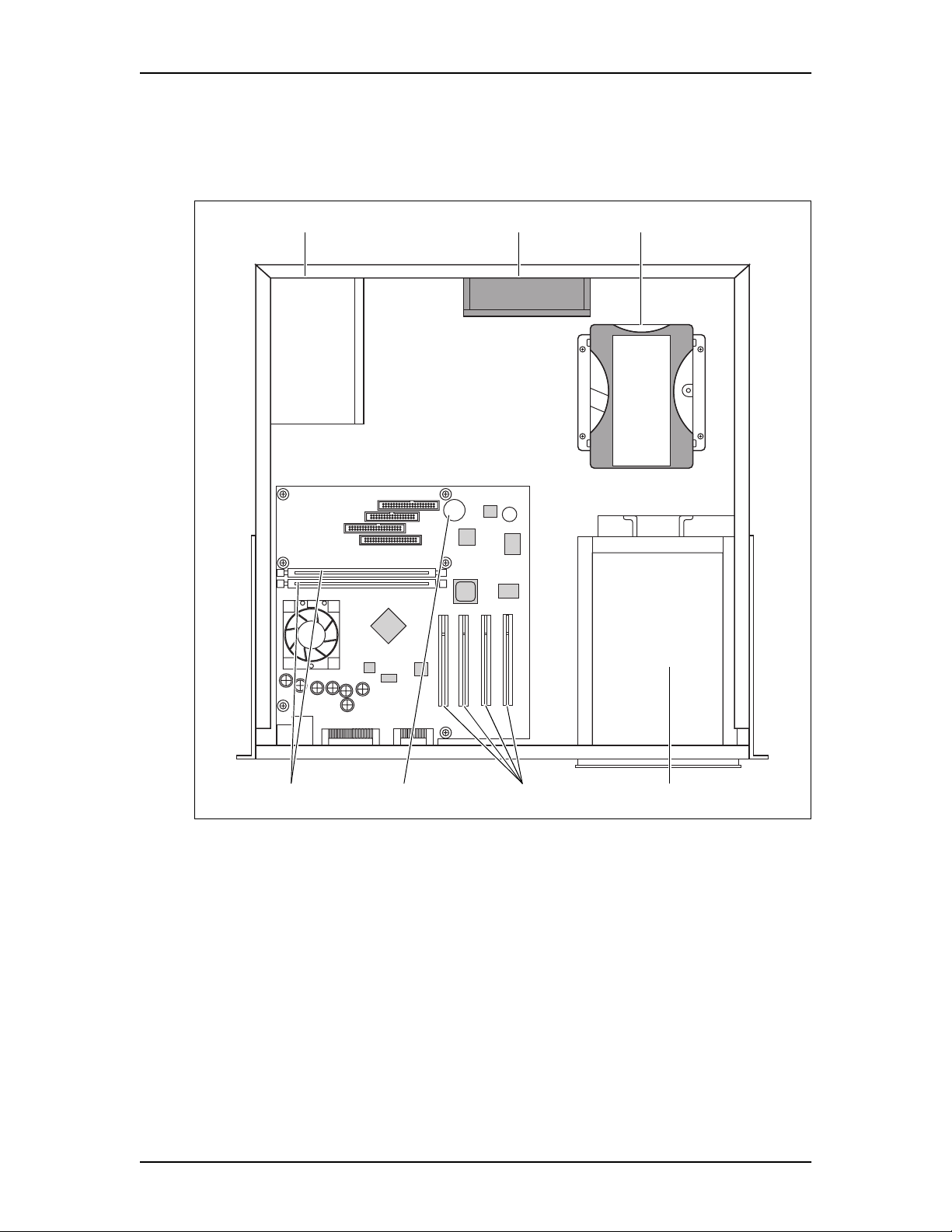
Figure 2 shows the location of the hardware components in the Enterprise Edge
server. Nortel Networks recommends you know the location of the different
components before working with the system.
Figure 2 Enterprise Edge server interior components
Hard diskFanPower s upply
DIMM slots
Media bay modulesClock/calendar battery PCI card slots
Enterprise Edge Installation and Maintenance Guide P0908507 Issue 02
Page 23
ComponentsoftheEnterpriseEdgeserver 23
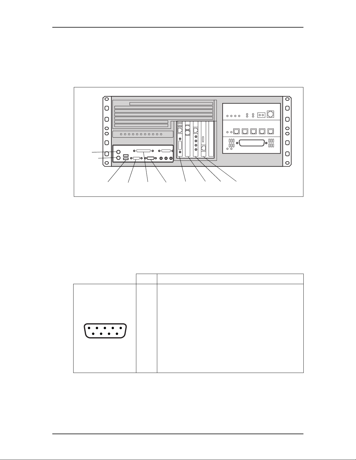
Connection Ports
External devices, such as a laptop computer or printer, connect to the Enterprise
Edge server through the connection ports. Figure 3 shows the location of the
different connection ports.
Figure 3 Enterprise Edge server external points of connection
Mouse
Keyboard
Parallel Serial
Modem LANWAN MSCMonitorUSB
Serial
The Enterprise Edge server is equipped with one serial port that supports
asynchronous serial data communication. The port has a maleDB-9 connector and
supports all standard baud rates (9600 default). You use the serial port to connect
serial devices, such as a laptop computer.
Table 1 Serial port connections
Pin Signal
1DataCarrierDetect(DCD)
2Serialdatain(RX)
3Serialdataout(TX)
12345
6789
4 Data Terminal Ready (DTR)
5Ground
6 Data Set Ready (DSR)
7 Request to Send (RTS)
8CleartoSend(CTS)
9 Ring Indicator (RI)
P0908507 Issue 02 Enterprise Edge Installation and Maintenance Guide
Page 24
24 Components of the Enterprise Edge server
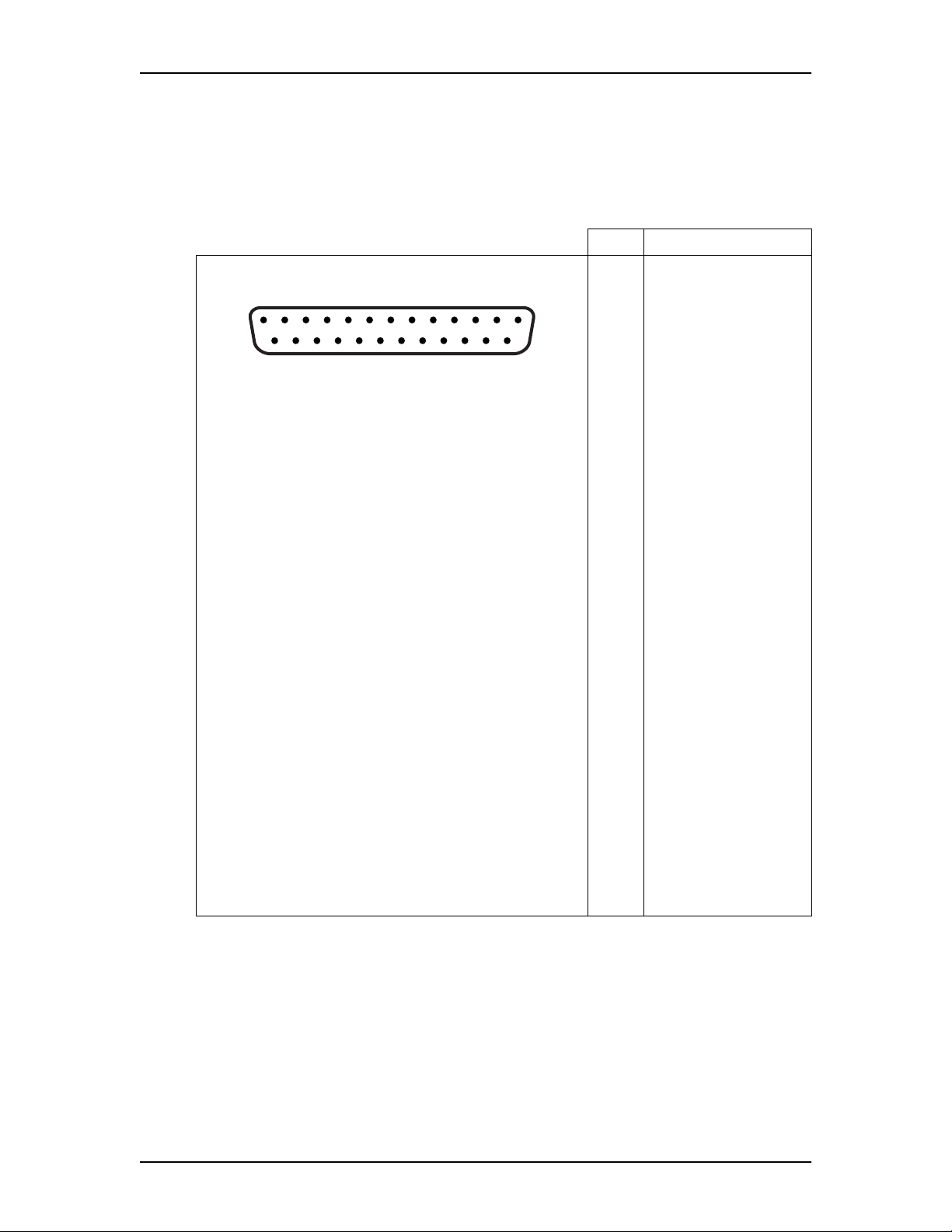
Parallel
The Enterprise Edge server is equipped with one parallel printer that features a
female DB-25 connector. This version of Enterprise Edge does not support the
parallel port.
Table 2 Parallel port connections
13121110987654321
25 24 23 22 21 20 19 18 17 16 15 14
Pin Signal
1STROBE
2 Parallel Data 0 (PD0)
3 Parallel Data 1 (PD1)
4 Parallel Data 2 (PD2)
5 Parallel Data 3 (PD3)
6 Parallel Data 4 (PD4)
7 Parallel Data 5 (PD5)
8 Parallel Data 6 (PD6)
9 Parallel Data 7 (PD7)
10 Acknowledge (ACK)
11 BUSY
12 PERROR
13 SELECT
14 AUDOFD
15 FAULT
16 INIT
17 SLCTIN
18 GND
19 GND
20 GND
21 GND
22 GND
23 GND
24 GND
25 GND
Enterprise Edge Installation and Maintenance Guide P0908507 Issue 02
Page 25
ComponentsoftheEnterpriseEdgeserver 25
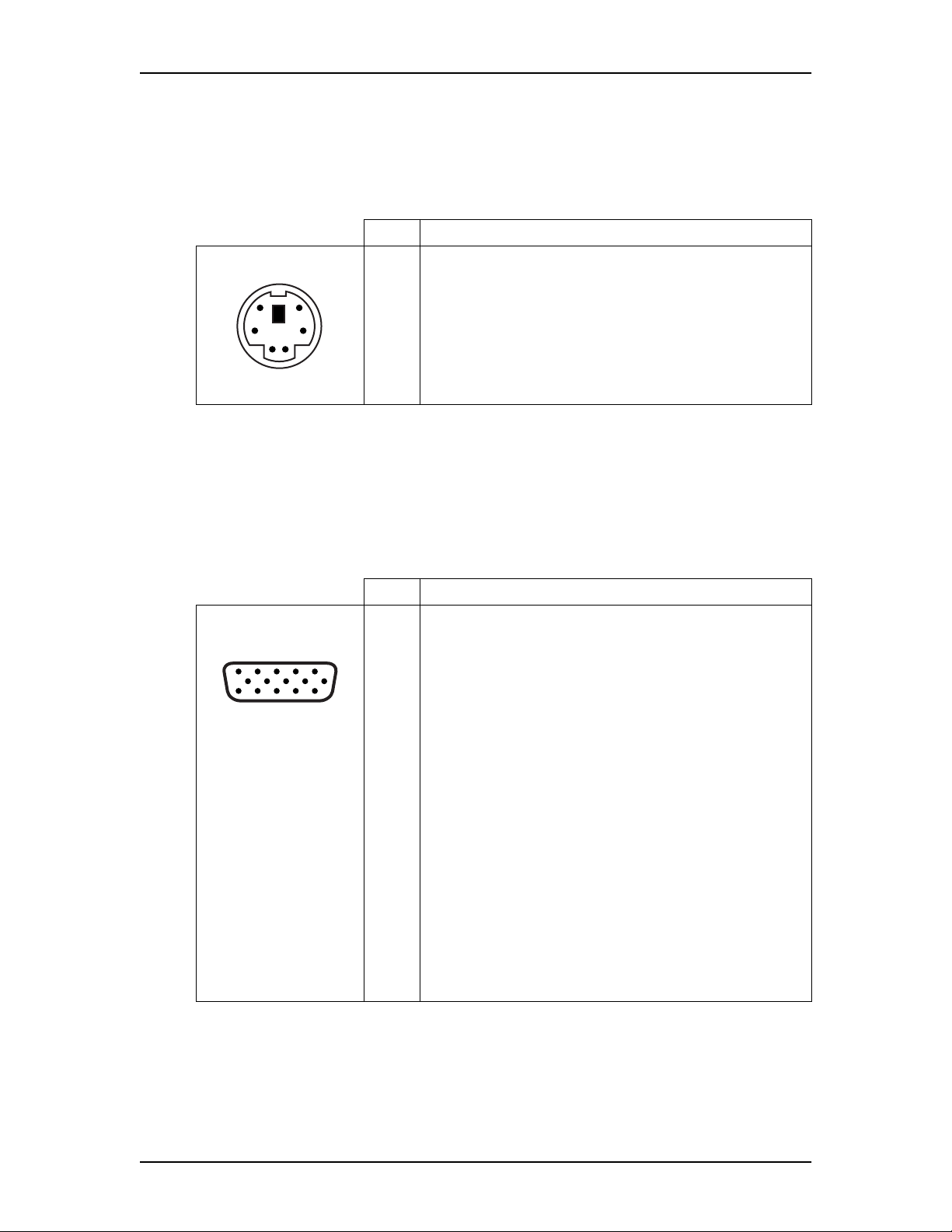
Keyboard and mouse
The EnterpriseEdge server is equipped with one keyboard port and onemouse port.
This version of Enterprise Edge does not support the keyboard or mouse.
Table 3 Keyboard and mouse port connections
Pin Signal
1Data
56
34
12
2Notconnected
3Ground
4+5Volts
5Clock
6Notconnected
Monitor
The Enterprise Edge server is equipped with one monitor port. This version of
Enterprise Edge does not support the monitor port.
Table 4 Monitor port connections
Pin Signal
1Red
2Green
5
15
1
610
11
3Blue
4Notconnected
5Ground
6Ground
7Ground
8Ground
9FusedVCC
10 Ground
11 Not connected
12 DDC_SDA
13 Horizontal SYNC
14 Vertical SYNC
15 DDC_SCL
USB Universal Serial Bus
The Enterprise Edge server is equipped with two USB ports. This version of
Enterprise Edge does not support the USB port.
P0908507 Issue 02 Enterprise Edge Installation and Maintenance Guide
Page 26

26 Components of the Enterprise Edge server
Enterprise Edge server LEDs
There are 10 LEDs on the front of the Enterprise Edge server. Table 5 describes the
use of each of the LEDs.
Table 5 Enterprise Edge server LEDs
LED Label Description
Power The Power LED lights when the Enterprise Edge server has power.
Disk The Disk LED lights when the Enterprise Edge server accesses the hard drive.
Status The Status LED lights when the Enterprise Edge system is operating correctly.
1 This LED is not used in this version of Enterprise Edge.
2 This LED is not used in this version of Enterprise Edge.
3 This LED is not used in this version of Enterprise Edge.
4 This LED is not used in this version of Enterprise Edge.
5 This LED is not used in this version of Enterprise Edge.
6 This LED is not used in this version of Enterprise Edge.
7 This LED is not used in this version of Enterprise Edge.
Software components
The Enterprise Edge system provides a number of software applications. Some of
these applications work immediately after you install the Enterprise Edge system.
To use other applications, you must enable the application using software key
codes. A software keycode is a password number provided to the installer. The
Enterprise Edge applications available are:
• Enterprise Edge Integrated Solution software
• Enterprise Edge Voice Messaging
• Enterprise Edge Call Center
• Enterprise Edge VoIP Gateway
• Enterprise Edge TSP
• Enterprise Edge Personal Call Manager
• Enterprise Edge Call Detail Recording
• Enterprise Edge Attendant Console
• Enterprise Edge Integrated QoS Routing
For more information about the software application packaging, refer to Software
applications on page 119.
Enterprise Edge Installation and Maintenance Guide P0908507 Issue 02
Page 27

ComponentsoftheEnterpriseEdgeserver 27
Enterprise Edge Integrated Solution software
EnterpriseEdge Integrated Solutionsoftware supplies standardtelephony operating
features that provide integrated communications on desktops. This software also
provides:
• Enterprise Edge Companion
• Programming, administration and maintenance
Enterprise Edge Companion
The Enterprise Edge Companion software provides wireless functionality without
losing the advantages of the wireline system. With Enterprise Edge Companion,
users can have one telephone number and receive all calls on both their desk
telephone and their portable.
Programming, administration and maintenance
The Enterprise Edge Unified Manager software provides programming,
administration and maintenance. Enterprise Edge Unified Manager provides a
series of windows and menusthat allowyou to navigate through thedifferent areas
of the application and easily enter information and program the system.
Enterprise Edge Voice Messaging
Enterprise Edge Voice Messaging provides the following features:
• Voice messaging
• Enterprise Edge Auto Attendant
• Custom Call Routing (CCR)
• Enterprise Edge Message Networking
• Enterprise Edge Unified Messaging
Voice messaging
Enterprise Edge Voice Messagingrecords incoming messages and stores them in a
mailbox foreasy retrieval. Each Enterprise Edge telephone in your system can have
a mailbox and a personal greeting.
Enterprise Edge Auto Attendant
Enterprise Edge Auto Attendant answers your business calls, 24 hours a day, with
a Company Greeting. A voice prompt then provides callers a menu of options to
direct their call by selecting a digit on the dialpad.
P0908507 Issue 02 Enterprise Edge Installation and Maintenance Guide
Page 28

28 Components of the Enterprise Edge server
Custom Call Routing (CCR)
CCR replaces the Auto Attendant menu with a custom CCR Home Menu. This
menu provides callers a wider range ofcall routing options and accessto submenus
and information messages. CCR allows you to determine the menu options and
record the voice prompts that guide callers along call paths.
Enterprise Edge Message Networking
Enterprise Edge Message Networking includes General Networking parameters,
Voice Profile for Internet Mail (VPIM) parameters, Audio Messaging Interchange
Specification(AMIS) specificparameters and AMIS Site Administration.For more
information about Message Networking, refer to the Enterprise Edge Message
Networking Set Up and Operation Guide.
Enterprise Edge Unified Messaging
Enterprise Edge Unified Messaging consists of three features:
• Enterprise Edge Unified Messaging allows you to create and receive
messages on your personal computer.
• Enterprise Edge Personal Mailbox Manager allows you to change mailbox
features andfunctions such as mailbox initialization andtargetattendant, record
greetings, and set up and maintain off-premise message notification.
• Enterprise Edge Operator Manager allows you to change the Operator
password, change business status, enable or disable the system attendant and
enable or disable the Call Answer feature.
Enterprise Edge Call Center
The Enterprise Edge Call Center is an Automatic Call Distribution (ACD) system
designed to handle incoming calls. Enterprise Edge Call Center answers incoming
calls and routes these calls to available agents. If there are no available agents, the
callers hear ACD greetings.
Enterprise Edge VoIP Gateway
Enterprise Edge VoIP Gateway allows you to use IP telephony. VoIP Gateway
converts the voice in a call into a packet format that can be sent over an intranet.
With Enterprise Edge VoIP Gateway, you can make telephone calls over any
intranet connected to the Enterprise Edge system.
Enterprise Edge TSP
Enterprise Edge TSP is the interface between the Enterprise Edge system and
Microsoft® TAPI. This interface allows you to use TAPI applications on the
Enterprise Edge system. For more information, refer to Enterprise Edge TSP Server
Configuration Guide.
Microsoft is a registered trademark of Microsoft Corporation.
Enterprise Edge Installation and Maintenance Guide P0908507 Issue 02
Page 29

ComponentsoftheEnterpriseEdgeserver 29
Enterprise Edge Personal Call Manager
Enterprise Edge Personal Call Manager is a TAPI application that provides First
Party Call Control for your telephone. For more information, refer to Enterprise
Edge Personal Call Manager User Guide.
Enterprise Edge Call Detail Recording
The Enterprise Edge Call Detail Recording software records call activity. When
your company makes or receives a call, Enterprise Edge Call Detail Recording
records the information about the call in Call Records.
Enterprise Edge Attendant Console
Enterprise Edge Attendant Console uses a graphical user interface to provide
centralized call management.
Enterprise Edge Integrated QoS Routing
Enterprise Edge Integrated QoS Routing is a router that controls the interface
between the Enterprise Edge system and the local area network, wide area network,
and internet.
P0908507 Issue 02 Enterprise Edge Installation and Maintenance Guide
Page 30

30 Components of the Enterprise Edge server
Enterprise Edge Installation and Maintenance Guide P0908507 Issue 02
Page 31

Telephony Hardware Description
The main telephony hardware components of the Enterprise Edge system are the:
• Media Services Card
• Station media bay modules
• Trunk media bay modules
• Telephones and adapters
The Media Services Card, station media bay modules and trunk media bay modules
are factory installed in the Enterprise Edge server. The telephones and adapters
connect to the Media Services Card and the media bay modules.
Media Services Card
The Enterprise Edge Media Services Card (MSC) is a PCI standard card which
performs call processing and media processing of the voice channels. The MSC has
four media services processorexpansion cards (MSPECs) installed, which provide
DSP resource control. For more information on MSPECs, refer to Media services
processor expansion cards (MSPECs) on page 34.
3
The MSC also provides the following functions.
• Connection between the MSC and the media bay modules
• Connection to optional equipment
Figure 4 Media Services Card
MSPEC installed here
DS256 interfaces
Hub connect
Miniature jacks
Connection between the MSC and the media bay modules
The MSC has four DS256 interfaces to connect to the media bay modules installed
intheserver.TheDS256connectorsare2x5pinheaderslocatedalongthetopedge
of the MSC. A 10-conductor ribbon cable connects the MSC to the media bay
modules.
P0908507 Issue 02 Enterprise Edge Installation and Maintenance Guide
Page 32

32 Telephony Hardware Description
Connection to optional equipment
The MSC has four 3.5 mm (1/8 inch) miniature jacks, located on the faceplate.
These jacks are standard miniature stereo (3-conductor) jacks. You use these
miniature jacks to connect the following optional equipment:
• Music on hold input
• Page output
• Page relay
• Auxiliary ringer
Figure 5 MSC optional equipment miniature jacks
Auxiliary ringer
Page relay
Page output
Music on hold input
External equipment connected to these interfaces must be SELV.
All four interfaces are Safety Extra Low Voltage (SELV) and the external
equipment connected to these interfaces must be SELV. If these interfaces are not
SELV, you must use external line isolation units (LIU).
Enterprise Edge Installation and Maintenance Guide P0908507 Issue 02
Page 33

TelephonyHardware Description 33
Music on hold input
The Enterprise Edge server uses the Music on hold input to connect an external
music source that supplies a signal to held lines (music on hold) or telephone
speakers (background music). The input source can be any available radio or music
source approved for connection to the network. The following specifications apply
to the Music on hold input:
• Nominal input impedance is 3.3 kilohms.
• Nominal sensitivity of this interface returned to digital encoded PCM is
-22 dBm0 for a 0.25 V rms input signal.
• The input is limited so that the encoded analog content at the digital interface to
the network will notexceed -12 dBm when averaged over any 3 second interval.
• The maximum non-clipped input level is 1 V rms.
• The interface is protected against ringing cross.
The music source connects to the tip and sleeve terminalsof the miniature jack. The
sleeve terminal of the jack connects to ground. You canuse eithera mono or stereo
plug to connect the music source. However, theMusic onhold input onlyaccepts a
mono input.
Page output
The Enterprise Edge server uses the page output to connect an internally generated
voice pagingsignal to an external paging amplifier(customer supplied). This signal
is transformer coupled and is floating with respect to earth ground. The signal has
a nominal source impedance of 600 ohms. The output level is 0 dBm0 with
reference to 600 ohms, for a PCM encoded signal at 0 dBM. There is no dc voltage
across the page output terminals.
The page output uses the tip and ring terminals of the jack. The sleeve terminal of
the jack connects to ground. You must use a stereo plug to connect the page signal
output.
Page relay
When you use the page signal output jack to connect an external paging amplifier,
you also use the page relay jack. The page relay jack connects a floating relay
contact pair.The Enterprise Edge serveruses this jack tocontrol the external paging
amplifier. The contact pair has a switch capacity of 50 mA (non-inductive) at 40 V
(maximum). You must remove any inductive load on the output.
The sleeve of the jack connects to ground. The page relay contacts connect to the
tip and ring terminals of the jack. You must use a stereo plug to connect the page
relay.
P0908507 Issue 02 Enterprise Edge Installation and Maintenance Guide
Page 34

34 Telephony Hardware Description
Auxiliary ringer
The Enterprise Edge server uses the auxiliary ringer jack to control the cadence of
an auxiliary ringer (customer supplied). You must use this output in a low current,
low voltage application only. Do not use this output for switching the auxiliary
ringer directly. The contact pair has a switch capacity of 50 mA (non-inductive) at
40 V (maximum). You must remove any inductive load on the output.
The sleeve of the jack connects to ground. The auxiliary ringer connects to the tip
and ring terminals of the jack. You must use a stereo plug to connect the auxiliary
ringer.
Media services processor expansion cards (MSPECs)
Each application uses DSP resources. The MSPECs control the DSP resources.
The MSC has four MSPECs installed. The MSPECs provide expansion capability
for Enterprise Edge Voice Messaging and Enterprise Edge Unified Messaging.
Station media bay modules
Station media bay modules connect to telephones and analog telecommunication
devices. The Enterprise Edge system includes the following station media bay
modules:
• 16-port Digital Station Media Bay Module (EE-DSM 16)
• 32-port Digital Station Media Bay Module (EE-DSM 32)
• Analog Station Media Bay Module (EE-ASM 8)
16-port Digital Station Media Bay M odule (EE-DSM 16)
The EE-DSM 16 connects up to 16 Enterprise Edge telephones to the Enterprise
Edge server. Figure 6 shows a diagram of the EE-DSM 16.
Each EE-DSM 16 has two LEDs on the faceplate labelled as follows:
• Power (indicates operating status)
• Status (indicates hardware status)
For more information about the LED states, refer toCheck that the power is on on
page 60.
The EE-DSM 16 has one amphenol connector on the faceplate. For details on the
EE-DSM 16 wiring, refer to Connect station media bay module wiring on page 67.
The back ofthe EE-DSM 16 has aDS256 connector that connects tothe MSC using
a 10-conductor ribbon cable. The back of the EE-DSM 16 also has a power
connector that connects power to the module. A set of DIP switches define the
extension numbers used by the EE-DSM 16.
Enterprise Edge Installation and Maintenance Guide P0908507 Issue 02
Page 35

TelephonyHardware Description 35
For more information about setting DIP switches,refer to Preparingfor anupgrade
on page 163.
Figure 6 EE-DSM 16
Front view
Power LED
Status LED
Amphenol
connector
Rear view
DS256 connector
DIP switches
power connector
32-port Digital Station Media Bay M odule (EE-DSM 32)
The EE-DSM 32 connects up to 32 Enterprise Edge telephones to the Enterprise
Edge server. Figure 7 shows a diagram of the EE-DSM 32.
Each EE-DSM 32 has two LEDs on the faceplate labelled as follows:
• Power (indicates working status)
• Status (indicates hardware status)
For more information about the LED states, refer toCheck that the power is on on
page 60.
The EE-DSM 32 has two amphenol connectors on the faceplate. For details on the
EE-DSM 32 wiring, refer to Connect station media bay module wiring on page 67.
The back ofthe EE-DSM 32 has aDS256 connector that connects tothe MCS using
a 10-conductor ribbon cable. The back of the EE-DSM 32 also has a power
connector that connects power to the module. A set of DIP switches define the
extension numbers used by the EE-DSM 32.
P0908507 Issue 02 Enterprise Edge Installation and Maintenance Guide
Page 36

36 Telephony Hardware Description
For more information about setting DIP switches,refer to Preparingfor anupgrade
on page 163.
Figure 7 EE-DSM 32
Power LED
Status LED
Amphenol
connectors
Front view
Rear view
DS256 connector
DIP switches
power c onnector
Analog Station Media Bay Module (EE-ASM 8)
The EE-ASM 8 connects up to eight analog telecommunication devices. These
devices can be standard home telephones, cordless telephones, FAX machines,
answering machines or modems. The maximum speed for a modem connection is
28.8 kbit/s. Figure 8 shows a diagram of the EE-ASM 8.
The EE-ASM 8 has two LEDs on the faceplate labelled as follows:
• Power (indicates working status)
• Status (indicates hardware status)
For more information about the LED states, refer toCheck that the power is on on
page 60.
The EE-ASM 8 has one amphenol connector on the faceplate. For details on the
EE-ASM 8 wiring, refer to Connect station media bay module wiring on page 67.
The back of the EE-ASM 8 has a DS256 connector that connects to the MSC using
a10-conductor ribbon cable. Theback of the EE-ASM8 also has a power connector
that connects power to the module. A set of DIP switches define the extension
numbers used by the EE-ASM 8.
Enterprise Edge Installation and Maintenance Guide P0908507 Issue 02
Page 37

TelephonyHardware Description 37
For more information about setting DIP switches,refer to Preparingfor anupgrade
on page 163.
Figure 8 EE-ASM 8
Front view
Power LED
Status LED
Amphenol
connector
Rear view
DS256 connector
DIP switches
power c onnector
Trunk media bay modules
Trunk media bay modules connect telecommunications trunks to the Enterprise
Edge system. The following types of trunk media bay modules are available:
• Digital Trunk Media Bay Module (EE-DTM)
• Caller ID Trunk Media Bay Module (EE-CTM)
P0908507 Issue 02 Enterprise Edge Installation and Maintenance Guide
Page 38

38 Telephony Hardware Description
Digital Trunk Media Bay Module (EE-DTM)
The EE-DTM (or Digital Trunk Interface) is a trunk module that connects a
standard digital PSTN T1 or PRI line to the Enterprise Edge system. With an
EE-DTM you can add up to 24 digital telephone lines to the Enterprise Edge
system. Figure 9 shows a diagram of the EE-DTM.
The EE-DTM has a number of status LEDs. For information about these LEDs,
refer to EE-DTM LED functions on page 39.
The front faceplate of the EE-DTM has a RJ48C connector that connects the
EE-DTM to the service provider’s connection point. The front faceplate also has a
set of Loopback connectors you use to run loopback tests. For details on loopback
tests, refer to the Enterprise Edge Programming Operations Guide.
The back of the EE-DTM has a DS256 connector thatconnects to the MSC using a
10-conductor ribbon cable. The back of the EE-DTM also has a power connector
that connects power to the module. A set of DIP switches define the line numbers
used by the EE-DTM.
For more information about setting DIP switches,refer to Preparingfor anupgrade
on page 163.
Figure 9 EE-DTM
Power LED
Status LED
In Service LED
Loopback Test LED
Continuity Loopback
Receive LEDs
Transmit LEDs
Loopback
RJ48C digital telephone line connector
Front view
Rear view
DS256 connector
DIP switches
power connector
Enterprise Edge Installation and Maintenance Guide P0908507 Issue 02
Page 39

TelephonyHardware Description 39
EE-DTM LED functions
The EE-DTM LED functions are:
• Power: A steady green LED on indicates that the DTM is receiving +5 Volts.
• Status: A steady green LED on indicates there is data communication between
the EE-DTM and the MSC card.
• In Service LED
• Loopback
• Receive Alarm
• Receive Error
• Transmit Alarm
• Transmit Error
All LEDs flashing continuously indicates that theEE-DTM is initializing. For more
information about the LED states, refer to Check that the power is on on page 60.
Caller ID Trunk Media Bay Module (EE-CTM)
The EE-CTM connects up to four analog CLID PSTN lines to the Enterprise Edge
server. The auxiliary port permits the connection of a 33.6+ kbit/s modem, FAX
machine or single lineanalog telephoneto line 1.When the auxiliary device isusing
line 1, the Enterprise Edge server does not allow other Enterprise Edge telephones
to use line 1. When you connect asingle line analog telephone to theauxiliary port,
you can use it as an emergency telephone. Figure 10 shows a diagram of the
EE-CTM.
Each EE-CTM has two LEDs on the faceplate labelled as follows:
• Power (indicates working status)
• Status (indicates hardware status)
For more information about the LED states, refer toCheck that the power is on on
page 60.
The back of the EE-CTM has a DS256connector that connects to the MSC using a
10-conductor ribbon cable. The back of the EE-CTM also has a power connector
that connects power to the module. A set of DIP switches define the line numbers
used by the EE-CTM.
For more information about setting DIP switches,refer to Preparingfor anupgrade
on page 163.
P0908507 Issue 02 Enterprise Edge Installation and Maintenance Guide
Page 40

40 Telephony Hardware Description
Figure 10 EE-CTM
Power LED
Status LED
Line 1
Aux
Line 2
Line 3
Line 4
Front view
Rear view
DS256 connector
DIP switches
power connector
Enterprise Edge Installation and Maintenance Guide P0908507 Issue 02
Page 41

Telephones and adapters
The following telephones and adapters are available with the Enterprise Edge
system.
• M7100
• M7208
• M7310
• M7324
• M7410
• Enterprise Edge central answering position (CAP)
• Enterprise Edge Analog Terminal Adapter 2 (ATA 2)
• Enterprise Edge Companion
M7100
The Enterprise Edge M7100 provides basic telephone coverage. It has a single line
display and one memory button without an indicator.
TelephonyHardware Description 41
M7208
The Enterprise Edge M7208 telephone has a single line display and eight memory
buttons with indicators.
M7310
The Enterprise Edge M7310 telephone has a two line display with three display
buttons, 10 memorybuttons with indicators and 12 double memory buttons without
indicators. With the 12 double memory buttons, you can access up to 24 additional
features or autodial numbers.
M7324
The Enterprise Edge M7324 telephone has a two line display with three display
buttons and 24 memory buttons with indicators. With the 24 memory buttons you
can access any combination of lines, featuresand autodial numbers. You can attach
two CAP modules to the M7324. Additional CAP modules give you call coverage
for many lines and provide space for additional features.
M7410
The Enterprise Edge M7410 telephone is a cordless telephone with the same
features as the M7310.
P0908507 Issue 02 Enterprise Edge Installation and Maintenance Guide
Page 42

42 Telephony Hardware Description
Enterprise Edge central answering position (CAP)
The CAP is a module you connect to an M7324 telephone that provides 48
additional memory buttons. These memory buttons add additional features or
autodial numbers or show a busy or idle status for up to 48 more telephones. You
can connectup to two CAPmodules to any M7324 telephone. You need one Station
Auxiliary Power Supply(SAPS) for every M7324 telephone that has CAP modules.
Enterprise Edge Station Auxiliary Power Supply (SAPS)
The SAPS extends the loop length between a telephone or terminal and the
Enterprise Edge server from1,000 to2,600 feet.You must use a dedicated cable to
connect the two locations.
The SAPS is also provides power for the Enterprise Edge central answering
position (CAP) module.
Enterprise Edge Analog Terminal Adapter 2 (ATA 2)
The Enterprise Edge ATA 2 converts digital signals to analog signals to allow
communication with a nalog devices such as FAX machines, modems and
answering machines. The ATA 2 supports a maximum transmission rate of 28.8
Kbit/s. With a single line telephone, the ATA 2 supports Off-Premises Extension
(OPX) or a long loop configuration. For more information, refer to Enterprise Edge
Analog Terminal Adapter 2 Installation Guide.
Enterprise Edge Companion
The hardware components which provide mobility functionality are:
• Companion Base Station
• C3050 Portable Handset
• Remote Power Interconnect (RPI) Unit
Companion Base Station
The Companion base station transmits and receives signals between the Enterprise
Edge server and portable handsets. Install the base stations on walls or ceilings.
Each base station provides radio coverage for a maximum of 32 cells.
C3050 Portable Handset
The C3050 CT2 Plus portable handset is available in Canada only. The Etiquette
C3050 portable handset is available in the USA only. You can assign the C3050
Portable Handset a separate telephone number or the same telephone number as the
person’s desktop telephone. It supports basic features such as call forward, call
transfer, conferencing and visual message waiting indication.
Enterprise Edge Installation and Maintenance Guide P0908507 Issue 02
Page 43

TelephonyHardware Description 43
Remote Power Interconnect (RPI) Unit
The RPI provides remote power for Base Station support. There are two types of
RPIs: RPI-8 that supports up to eight Base Stations and RPI-16 that supports up to
16 Base Stations.
P0908507 Issue 02 Enterprise Edge Installation and Maintenance Guide
Page 44

44 Telephony Hardware Description
Enterprise Edge Installation and Maintenance Guide P0908507 Issue 02
Page 45

Data Hardware Description
The main data hardware components of the Enterprise Edge system are the:
• Modem card
• LAN card
• WAN card
The modem card, LAN card and WAN card are factory installed in the Enterprise
Edge server.
Modem card
The modem card is a V.90 interface modem. This modem connects the Enterprise
Edge server to the public switched telephonenetwork. You can use thisconnection
to manage the Enterprise Edge system from a different location. You also use this
card as a dial in backup for the Enterprise Edge Integrated QoS Routing.
4
LAN card
The LAN card connects the Enterprise Edge server to the Local Area Network
(LAN). This card is a 10/100 Base T Ethernet Network Interface Card.
WAN card
The WAN card connects the Enterprise Edge server to the Wide Area Network
(WAN). This card connects to a T1 PSTN line and supports two integrated T1
DSU/CSUs.
P0908507 Issue 02 Enterprise Edge Installation and Maintenance Guide
Page 46

46 Data Hardware Description
Enterprise Edge Installation and Maintenance Guide P0908507 Issue 02
Page 47

Section II - How to install the
Enterprise Edge system
•InstallationOverview
• How to install the Enterprise Edge server
• Start the Enterprise Edge server
• Install the telephony hardware
• Install Enterprise Edge Companion Wireless
• Install the Data Networking Hardware
P0908507 Issue 02 Enterprise Edge Installation and Maintenance Guide
Page 48

48 How to install the Enterprise Edge system
Enterprise Edge Installation and Maintenance Guide P0908507 Issue 02
Page 49

Installation Overview
To install the Enterprise Edge server, you must:
Install the Enterprise Edge server
The Enterprise Edge server is the main computing device in the Enterprise Edge
system. It also contains the telephony and data networking components. For
instructions on how to install theEnterprise Edgeserver, refer to How to install the
Enterprise Edge server on page 51.
Install the Enterprise Edge telephony components
The telephony components of the Enterprise Edge system provide call processing
functions andconnectionto the public telephone system.For instructions on how to
install the telephony components, refer to Install the telephony hardware on page
63.
Install the Enterprise Edge data networking components
The data networking components of the Enterprise Edge system provide network
connection to your local area network (LAN) and your wide area network (WAN).
For instructions on how to install the data networking components, refer to Install
the Data Networking Hardware on page 109.
5
Install the Enterprise Edge software
The Enterprise Edge software provides features such as call processing, voice
messaging and data routing. For instruction on how to install the software, refer to
Enterprise Edge Software on page 119.
P0908507 Issue 02 Enterprise Edge Installation and Maintenance Guide
Page 50

50 Installation Overview
Enterprise Edge Installation and Maintenance Guide P0908507 Issue 02
Page 51

How to install the Enterprise Edge server
Introduction
This section describes how to install the Enterprise Edge system and prepare it for
operation.
Before you start
Before you start the installation, ensure that you:
• read this guide and understand the installation process
• check that all conditions are met in the checklists
Preparation checklist
Identify the required resources (number and type of trunks and number and
type of telephones).
Check that your Enterprise Edge server has the minimum requirements. Refer
to Enterprise Edge server configurations on page 53.
6
Check that you have all the equipment and supplies you need to install the
system.
Determine the location for the Enterprise Edge server, telephones, and other
equipment based on spacing and electrical requirements. For more
information about spacing and electrical requirements, refer to the
documentation shipped with your hardware.
Order the required trunks from the central office.
Packaging Checklist
Make sure the package you received contains the following items:
Enterprise Edge server
Enterprise Edge server rack mounting bracket
rubber feet
AC power cord
P0908507 Issue 02 Enterprise Edge Installation and Maintenance Guide
Page 52

52 How to install the Enterprise Edge server
Environment Checklist
The installation area must be:
at least 4 m (approximately13 feet) from equipment such as photocopiers,
electrical motors and other equipment that can produce electromagnetic, radio
frequency and electrostatic interference
within 1.5 m (approximately 5 feet) of a three wire grounded electrical outlet
clean, free of traffic and excess dust, dry and well ventilated
temperature between 0°C and 35°C (32°F and 95°F)
between 20% and 80% non-condensing relative humidity
available space in an equipment rack or on a table that is capable of
supporting the Enterprise Edge server
a minimum of 46 cm (approximately 18 inches) from the floor
Note: The distance from the floor to the installation area must be enough to
prevent water damage.
Electrical requirements
non-switched, unobstructed outlet within 1.5 m (5 ft) of the Enterprise Edge
server.
dedicated 110 V - 120 V ac nominal, 50/60 Hz, 15 A minimum service with a
third wire safety ground. The third wire safety ground provides shock
protection and avoids electromagnetic interference.
Risk of electric shock.
The safety of this product requires connection to an outlet with a third wire
ground. Use only with a three wire power cord and outlet.
Check ground connections.
Ensure that the electrical ground connections of the power utility, telephone
lines and internal metal water pipe system, if present, are connected
together. If these ground connection are not connected together, contact the
appropriate electrical inspection authority. Do not try to make the
connections yourself.
The Enterprise Edge server power cord is 1.5 m (5 ft) long. You can connect
the server to a power bar with a maximum length of 2 meters (6.5 ft),
including power bar. You must use a power bar approved by an appropriate
National Test Body, with a third wire ground. Do not use an extension cord
between the server and the power bar, or between the power bar and the
electrical outlet.
Enterprise Edge Installation and Maintenance Guide P0908507 Issue 02
Page 53

HowtoinstalltheEnterpriseEdgeserver 53
Internal wiring requirements
Digital loop
one, two or three twisted-pair cable(s) per telephone
dc loop resistance of less than 64 Ω
cable length (0.5 mm or 24 AWG) less than 300 m (975 ft)
use of a station auxiliary power supply (SAPS) for loops 300 m (975 ft) to
1200 m (3900 ft). The SAPS must be a Class 2 power source that is approved
by an appropriate National Test Body.
no bridge taps
Analog loop
maximum dc loop resistance of 208 Ω
maximum cable length (0.5 mm or 24 AWG) of 1220 m (4000 ft)
Enterprise Edge server configurations
Table 6 and Table 7 show the Enterprise Edge server configurations available. You
can identify your configuration by the number and type of media bay modules
installed.
Table 6 Enterprise Edge server configuration available in North America
Configurations
8x16
2LAN
Modem card 11111111 1
LAN card 21212121 2
WAN card 1111
EE-CTM 222211
EE-DTM 1111 2
EE-ASM 8
EE-DSM 16 11
EE-DSM 32 111122 1
Maximum
number of
telephones
16 16 32 32 32 32 64 64 32
8x16
WAN
8x32
2LAN
8x32
WAN
28 x 32
2LAN
28 x 32
WAN
24 x 64
2LAN
24 x 64
WAN
48 x 32
2LAN
Maximum
number of
analog trunks
Maximum
number of
digital trunks
P0908507 Issue 02 Enterprise Edge Installation and Maintenance Guide
888844
24 24 24 24 48
Page 54

54 How to install the Enterprise Edge server
Table 7 Enterprise Edge server configurations available outside of North America
Configurations
8x16
LAN
LAN card 22222222 2
WAN card 1111
EE-BRIM S/T 112211
EE-DTM 1111 2
EE-DSM 16 11
EE-DSM 32 111122 1
Maximum
number of
telephones
Maximum
number of
analog trunks
Maximum
number of
digital trunks
16 16 32 32 32 32 64 64 32
8 8 16 16 8 8
8x16
WAN
16 x 32
LAN
16 x 32
WAN
38 x 32
LAN
30 30 30 30 60
38 x 32
WAN
30 x 64
LAN
30 x 64
WAN
60 x 32
LAN
System equipment and supplies
Use the following checklists to check that you have all the required equipment.
Basic hardware
Enterprise Edge server
Enterprise Edge telephones
M7100
M7208
M7310
M7324
M7410
Optional equipment
station auxiliary power supply (SAPS)
central answering position (CAP) module
Enterprise Edge Analog Terminal Adapter 2 (ATA 2)
uninterruptible power supply (UPS)
analog emergency telephone
Enterprise Edge Installation and Maintenance Guide P0908507 Issue 02
Page 55

Enterprise Edge Companion equipment
Enterprise Edge C 3050 CT2 Plus (Canada only)
Base Station kit
Handsets (C3050)
Battery packs (NiCad 450 hours)
Battery packs (NiCad 600 hours)
Enterprise Edge C3050 Etiquette (USA only)
Base Station kit
Handsets (C3050)
Battery packs (NiCad 450 hours)
Battery packs (NiCad 600 hours)
High capacity battery charger
Other Companion equipment
Holster
HowtoinstalltheEnterpriseEdgeserver 55
Holster clip
Headset
Headset - “over the head”
Equipment for installing the Enterprise Edge system
For the installation, you need the following equipment:
rack mounting bracket
four rubber feet
Phillips screwdriver #2
flat blade screwdriver
pliers
antistatic grounding strap
connecting tool
surge protector (recommended)
Cables
25-pair cable with amphenol connectors
P0908507 Issue 02 Enterprise Edge Installation and Maintenance Guide
Page 56

56 How to install the Enterprise Edge server
Install the Enterprise Edge server in a rack
The Enterprise Edge server installs in a standard 19" equipment rack. You can
install the Enterprise Edge server in the same rack as your other networking and
telecommunications equipment.
CAUTION
When installing the Enterprise Edge server in a rack, do not stack units directly
on top of one another in the rack. Secure each unit to the rack with the
appropriate mounting brackets. Mounting brackets cannot support multiple
units.
CAUTION
Refer to Environment Checklist
selecting a location for theEnterprise Edge server.
Attach the rack mounting bracket to the Enterprise Edge server
for acceptable environmental conditions before
1. Place the Enterprise Edge server on a table.
2. Align the screw holes between the Enterprise Edge server and the right rack
mounting bracket.
3. Fasten the bracket to the Enterprise Edge server using four screws.
4. Align the screw holes between the Enterprise Edge server and the left rack
mounting bracket.
5. Fasten the bracket to the Enterprise Edge server using four screws.
Caution
Only use the screws that came with the rack mounting bracket. Do not
replace screws. Other screws can damage the Enterprise Edge server.
Enterprise Edge Installation and Maintenance Guide P0908507 Issue 02
Page 57

HowtoinstalltheEnterpriseEdgeserver 57
Figure 11 Attach the rack mounting bracket to the Enterprise Edge server
Install the Enterprise Edge server in the rack
1. Determine the location in the rack you want to install the Enterprise Edge
server.
2. Position the Enterprise Edge server in the rack.
3. Align the holes in the rack mounting bracket with the holes in the rails.
4. Fasten the rack mounting brackets to the rack using four screws (not
supplied).
P0908507 Issue 02 Enterprise Edge Installation and Maintenance Guide
Page 58

58 How to install the Enterprise Edge server
Figure 12 Fasten the Enterprise Edge server to the rack
Install the Enterprise Edge server on a table or shelf
You can install the Enterprise Edge server on any surface that can support the
weight of the unit.
CAUTION
Refer to Environment Checklist
selecting a location for theEnterprise Edge server.
for acceptable environmental conditions before
To install the Enterprise Edge server on a table or shelf:
1. Attach a rubber foot to the four corners on the bottom of the Enterprise Edge
server.
2. Position the Enterprise Edge server on the table or shelf. Make sure you leave
enough space around the unit for ventilation and access to the cables.
Enterprise Edge Installation and Maintenance Guide P0908507 Issue 02
Page 59

Start the Enterprise Edge server
To start the Enterprise Edge server:
1. Make sure the power supply is set to the voltage available at your electrical
outlet.
CAUTION
This unit is set at the factory to use 1 15volts AC. Failure to change the
power supply voltage setting when using 230 volts AC will damage the unit
beyond repair. For information about changing the power supply voltage,
refer to Change the power supply voltage
2. Check all wiring before turning the system power on. Do not connect central
office line cables to the Enterprise Edge system until after turning the system
power on.
3. Connect the Enterprise Edge server power cord to an electrical outlet that is a
non-switchable, third wire ground AC outlet.
7
on page 61.
If you are using a power bar, plug the power cords into the power bar and
connect the power bar to the AC outlet.
Do not fasten power supply cords.
Do not fasten the Enterprise Edge server power supply cord to any building
surface, including the backboard.
P0908507 Issue 02 Enterprise Edge Installation and Maintenance Guide
Page 60

60 Start the Enterprise Edge server
Check that the power is on
After you connect power to the Enterprise Edge server, the LEDs on the faceplate
of the modules light. Telephones and lines can take 5 minutes to initialize.
There are two LEDs on the faceplate:
• Power (indicates working status)
• Status (indicates hardware status)
Table 8 LED states
Power Status Details
Off Off No power applied to the module or failure of module power
converter
On Off Field Programmable Gate Array (FPGA) not downloaded which
indicatesthattheMSChasnotstartedcorrectly.)
On Blinking Operation problem exists
• no DS256 link detected
• DS256 frame alignment lost
• Bandwidth not allocated
• Module is in maintenance state
Note: DS256 is the bus that connects the media bay modules to
the MSC.
Blinking Blinking Hardware problem
• partial failure of p ower converter
•thermaloverload
•fanfailure
On On Module is ready to operate
Tips
During system initialization, the system performs diagnostics on the
hardware configuration size and installation.
If the power fails, your system data is retained.
Enterprise Edge Installation and Maintenance Guide P0908507 Issue 02
Page 61

Change the power supply voltage
The power supply on the Enterprise Edge server is set at the factory to operate at
115 volts. If you plan to use 115 volts to power the Enterprise Edge server, do not
change the voltage switch. If you plan to use 230 volts, you must change the power
supply voltage setting before connecting power to the Enterprise Edge server.
To change the power supply setting:
1. Shutdown the Enterprise Edge server. For more information, refer to
Shutdown the Enterprise Edge server on page 127.
2. Remove the Enterprise Edge server power cord from the AC outlet.
3. Slide the power supply switch, installed on the back of the power supply, so
that the required voltage label appears (115 or 230).
4. Plug the power cord into the AC socket.
Figure 13 Change the power supply voltage
Start the Enterprise Edge server 61
Power supply switch
CAUTION
This unit is set at the factory to use 115 volts AC. Failure to change the power
supply voltage setting when using 230 volts AC will damage the unit beyond
repair.
P0908507 Issue 02 Enterprise Edge Installation and Maintenance Guide
Page 62

62 Start the Enterprise Edge server
Enterprise Edge Installation and Maintenance Guide P0908507 Issue 02
Page 63

Install the telephony hardware
Only qualified persons should service the system.
The installation and service of this unit is to be performed only by service
personnel having appropriate training and experience necessary to be aware of
hazards to which they are exposed in performing a task and of measures to
minimize the danger to themselves or other persons.
Electrical shock hazards from the telecommunication network and ac mains are
possible with this equipment. To minimize risk to service personnel and users,
the Enterprise Edge system must be connected to an outlet with a third wire
ground. In addition, all unused slots should have filler faceplates installed and
the cover must be in place at the completion of any servicing.
Service personnel must be alert to the possibility of high leakage currents
becoming available on metal system surfaces during power line fault events
near network lines. These leakage c urrents normally safely flow to Protective
Earth ground via the power cord. Therefore, it is mandatory that connection to
an earthed outlet is performed first and removed last when cabling to the unit.
Specifically, operations requiring the unit to be powered down must have the
network connections (central office lines) removed first.
8
Task over view
When installing the Enterprise Edge system, perform the following tasks:
• Connect the wiring
• Install the telephones
• Install the Enterprise Edge Analog Terminal Adapter 2
• Install other optional equipment
P0908507 Issue 02 Enterprise Edge Installation and Maintenance Guide
Page 64

64 Install the telephony hardware
Note: Read and follow the safety warning below.
Risk of shock.
EnsuretheEnterpriseEdgeserverisunpluggedfromthepowersocketandthat
any telephone or network cables are unplugged before opening the Enterprise
Edge server.
Do not connect the tele-adapt ports of the EE-DSM 16 or EE-DSM 32 to the
Public Switched Telephone Network (PSTN). Only approved digital telephones
or peripherals can be connected to the EE-DSM 16 or EE-DSM 32.
Do not connect any telephones to telephone wiring that runs outside of the
building.
The Enterprise Edge media bay modules have been Safety approved for
installation into PC servers. It is the responsibility of the installer and user to
ensure that installation of the Enterprise Edge hardware does not compromise
existing Safety approvals.
Do not connect the EE-DSM 16, EE-DSM 32 or EE-ASM 8 ports to any cables
that run outside a building.
Read and follow the installation instructions carefully.
Wiring overview
Figure 14 shows the wiring required to connect the trunk and station modules to
digital or analog station sets.
Figure 14 Wiring overview
Enterprise Edge server*
EE-CTM
EE-DTM
EE-DSM 16/
EE-DSM 32
EE-ASM 8
*The Enterprise Edge server can only
have three media bay modules.
To analog lines from
service provider
To digital lines from
service provider
To Enterprise Edge
digital telephones
To analog telephony
devices
Enterprise Edge Installation and Maintenance Guide P0908507 Issue 02
Page 65

Connect the wiring
This section describes how to wire the trunk and station media bay modules to the
network. For the purposes of this section, the following guidelines apply:
• Each telephone uses a single pair of wires to connect to the Enterprise Edge
server.
• All descriptions and installations use BIX standards.
When wiring the media bay modules to the network, there are two major tasks you
must perform:
• Connect trunk media bay module wiring
• Connect station media bay module wiring
For an overviewof the complete process, refer to the diagram Wiring overview on
page 64.
Connect trunk media bay module wiring
Install the telephony hardware 65
The wire the EE-DTM and EE-CTM modules to the network using the following
procedures:
• Connect EE-DTM wiring
• Connect EE-CTM wiring
P0908507 Issue 02 Enterprise Edge Installation and Maintenance Guide
Page 66

66 Install the telephony hardware
Connect EE-DTM wiring
Connect the cable to the RJ-48C connector on the front ofthe EE-DTM module and
the service provider’s connection point. Figure 15 shows a connection between an
EE-DTM module and the service provider. This diagram includes a BIX block
connection.
Figure 15 Connect wiring to an EE-DTM
EE-DTM
wiredtoCSUorserviceprovider
BIX blocks
Note: Ifyou are using the service provider’s CSU, you must disable the Enterprise
Edge server’s internal CSU using Enterprise Edge Unified Manager. For
more information, refer to the Enterprise Edge Programming Operations
Guide.
Connect EE-CTM wiring
Connect the cable to the RJ-11 connector on the front of the EE-CTM and the
service provider’s connection point. Figure 16 shows a connection between a
EE-CTM module and the service provider. This connection includes a BIX block
connection.
Figure 16 Connect wiring to an EE-CTM
wired to CSU or service provider
EE-CTM
Enterprise Edge Installation and Maintenance Guide P0908507 Issue 02
Page 67

Install the telephony hardware 67
Connect station media bay module wiring
To connect the wiring for the EE-DSM 16, EE-DSM 32 or EE-ASM 8 media bay
modules:
1. Plug the amphenol connector into the EE-DSM 16, EE-DSM 32 and
EE-ASM 8 station interface.
2. Wire the 25 pair cable to the cross connect array.
3. Connect another 25 pair cable between the telephones cross connect array and
the station interface cross connect array. The cross connection allows
connections between telephones and the station interfaces.
For an overview of BIX wiring conventions, refer to Appendix A: BIX
overview on page 243.
Note: If you are connecting an EE-DSM 16 or EE-DSM 32, use the Wiring
chart for Digital Station Media Bay Modules on page 69. This diagram
shows how to connect the ports you connected in step 2 to the station
sets you connected in step 3.
If you are connecting an EE-ASM 8, use the Wiring chart for Analog
Station Media Bay Module (EE-ASM 8) on page 71. This diagram
show how to connect the ports you connected in step 2 to the station
sets you connected in step 3.
Figure 17 Cross connections for an EE-DSM 16 or EE-ASM 8
P0908507 Issue 02 Enterprise Edge Installation and Maintenance Guide
Page 68

68 Install the telephony hardware
Figure 18 Cross connections for a EE-DSM 32
4. Attach the station set cables to the connecting blocks.
5. Install the telephones.
For information about installing telephones, refer to Install the telephones on
page 72.
Enterprise Edge Installation and Maintenance Guide P0908507 Issue 02
Page 69

Install the telephony hardware 69
Wiring chart for Digital Station Media Bay Modules
Thiswiring chart applies toboth the EE-DSM 16and the EE-DSM 32. Wire the two
amphenol connectors on the EE-DSM 32 the same way.
Pin Wire color Port Service Telephones SM
26 White-Blue X01 T 1
1 Blue-White X01 R 1
27 White-Orange X02 T 2
2 Orange-White X02 R 2
28 White-Green X03 T 3
3Green-WhiteX03 R 3
29 White-Brown X04 T 4
4 Brown-White X04 R 4
30 White-Slate X05 T 5
5Slate-White X05 R 5
31 Red-Blue X06 T 6
6 Blue-Red X 06 R 6
32 Red-Orange X07 T 7
7 Orange-Red X07 R 7
33 Red-Green X08 T 8
8Green-Red X08 R 8
34 Red-Brown X09 T 9
9 Brown-Red X09 R 9
35 Red-Slate X10 T 10
10 Slate-Red X10 R 10
36 Black-Blue X11 T 11
11 Blue-Black X11 R 11
37 Black-Orange X12 T 12
12 Orange-Black X12 R 12
38 Black-Green X13 T 13
13 Green-Black X13 R 13
39 Black-Brown X14 T 14
14 Brown-Black X14 R 14
40 Black-Slate X15 T 15
15 Slate-Black X15 R 15
41 Yellow-Blue X16 T 16
16 Blue-Yellow X16 R 16
42 Yellow-Orange ---- ---- no connection
17 Orange-Yellow ---- ---- no connection
43 Yellow-Green ---- ---- no connection
18 Green-Yellow ---- ---- noconnection
44 Yellow-Brown ---- ---- no connection
19 Brown-Yellow ---- ---- no connection
45 Yellow-Slate ---- ---- no connection
20 Slate-Yellow ---- ---- no connection
46 Violet-Blue ---- ---- no connection
21 Blue-Violet ---- ---- no connection
47 Violet-Orange ---- ---- no connection
22 Orange-Violet ---- ---- no connection
48 Violet-Green ---- ---- no connection
23 Green-Violet ---- ---- no connection
49 Violet-Brown ---- ---- no connection
24 Brown-Violet ---- ---- no connection
50 Violet-Slate ---- ---- no connection
25 Slate-Violet ---- ---- no connection
P0908507 Issue 02 Enterprise Edge Installation and Maintenance Guide
Page 70

70 Install the telephony hardware
Connection between EE-DSM 16 and EE-DSM 32 modules and telephones
Table 9 lists the connections between the wire pairs and the module sets.
Table 9 Connectors on both the EE-DSM 16 and EE-DSM 32
Connector on both EE-DSM 16
and EE-DSM 32
Pair Module set number Pair Module set number
1, 26 1 1, 26 17
2, 27 2 2, 27 18
3, 28 3 3, 28 19
4, 29 4 4, 29 20
5, 30 5 5, 30 21
6, 31 6 6, 31 22
7, 32 7 7, 32 23
8, 33 8 8, 33 24
9, 34 9 9, 34 25
10, 35 10 10, 35 26
11, 36 11 11, 36 27
12, 37 12 12, 37 28
13, 38 13 13, 38 29
14, 39 14 14, 39 30
15, 40 15 15, 40 31
16, 41 16 16, 41 32
Connector on EE-DSM 32 only
Enterprise Edge Installation and Maintenance Guide P0908507 Issue 02
Page 71

Install the telephony hardware 71
Wiring chart for Analog Station Media Bay Module (EE-ASM 8)
Pin Wire color Port Service Telephones SM
26 White-Blue X01 T 1
1 Blue-White X01 R 1
27 White-Orange X02 T 2
2 Orange-White X02 R 2
28 White-Green X03 T 3
3Green-WhiteX03 R 3
29 White-Brown X04 T 4
4 Brown-White X04 R 4
30 White-Slate X05 T 5
5Slate-White X05 R 5
31 Red-Blue X06 T 6
6 Blue-Red X 06 R 6
32 Red-Orange X07 T 7
7 Orange-Red X07 R 7
33 Red-Green X08 T 8
8Green-Red X08 R 8
34 Red-Brown no connection
9 Brown-Red no connection
35 Red-Slate no connection
10 Slate-Red no connection
36 Black-Blue no connection
11 Blue-Black no connection
37 Black-Orange no connection
12 Orange-Black no connection
38 Black-Green no connection
13 Green-Black no connection
39 Black-Brown noconnection
14 Brown-Black no connection
40 Black-Slate no connection
15 Slate-Black no connection
41 Yellow-Blue no connection
16 Blue-Yellow no connection
42 Yellow-Orange no connection
17 Orange-Yellow no connection
43 Yellow-Green no connection
18 Green-Yellow no connection
44 Yellow-Brown no connection
19 Brown-Yellow no connection
45 Yellow-Slate no connection
20 Slate-Yellow no connection
46 Violet-Blue no connection
21 Blue-Violet no connection
47 Violet-Orange noconnection
22 Orange-Violet no connection
48 Violet-Green noconnection
23 Green-Violet no connection
49 Violet-Brown no connection
24 Brown-Violet no connection
50 Violet-Slate no connection
25 Slate-Violet no connection
P0908507 Issue 02 Enterprise Edge Installation and Maintenance Guide
Page 72

72 Install the telephony hardware
Install the telephones
Use the following procedures when installing the Enterprise Edge system
telephones.
• Install digital and analog telephones
• Install Companion wireless sets
• Install the emergency telephone
• Install the Enterprise Edge central answering position (CAP)
• Install the Enterprise Edge Analog Terminal Adapter 2
Install digital and analog telephones
For installation procedures for digital and analog telephones, refer to instruction
cards that came with the telephones.
Do not use telephones as off-premises extensions (OPX)
For OPX applications, use the Enterprise Edge Analog Terminal Adapter and a
single-line telephone.
Install Companion wireless sets
On the Enterprise Edge servers with one EE-DTM and two EE-DSM32, installthe
base stations on the center EE-DSM 32. The center module is the EE-DSM 32
between the EE-DTM and the second EE-DSM 32.
Use the following basic steps to install your Companion wireless set.
1. Install the remote power interconnect.
2. Install the Base Stations.
3. Install the portable telephones.
4. Install the external antennas and lightning surge protectors.
5. Power up the system.
For more information about installing Companion wireless sets, refer to the
Enterprise Edge Programming Operations Guide.
Enterprise Edge Installation and Maintenance Guide P0908507 Issue 02
Page 73

Install the telephony hardware 73
Install the emergency telephone
You can use the emergency telephone to make calls when there is no power to the
Enterprise Edge server.
To install an emergency telephone on the Enterprise Edge server, connect a single
line analog telephone to the auxiliary port on the EE-CTM. When you make a call
from the emergency telephone, theauxiliary port usesthe telephone lineconnected
to the Line 1 port of the EE-CTM.
Tip
You can connect an emergency telephone to every EE-CTM you have
installed on your Enterprise Edge system.
Use the following steps to install the emergency telephone.
1. Connect a single line analog telephone (500/2500) to the auxiliary port on the
EE-CTM.
2. Connect an analog PSTN line to the Line 1 port of the EE-CTM.
3. Lift the emergency telephone receiver and listen for dial tone.
Install the Enterprise Edge central answering position (CAP)
The CAP is a module connected to an M7324 telephone that provides48 additional
memory buttons. For installation procedures for the CAP, refer to the installation
documents that came with the CAP.
P0908507 Issue 02 Enterprise Edge Installation and Maintenance Guide
Page 74

74 Install the telephony hardware
Install the Enterprise Edge Analog Terminal Adapter 2
TheEnterprise EdgeAnalog Terminal Adapter2 (Enterprise EdgeATA 2)connects
a standard analog voice device or data communication device to the Enterprise
Edge server. Examples of analog voice devices are single-line telephones or
answeringmachines. Examples of data communicationdevices aremodems andfax
machines. The Enterprise Edge ATA 2 provides on or off-premise service.
Before Installation
Check the following environment requirements for Enterprise Edge ATA 2:
Line voltage (110 V) 92 – 127 V ac
Line voltage (220 V) 180 – 264 V ac
Temperature 0 – 50°C (32 – 122°F)
Relative humidity 5% – 95% non-condensing
Bridge taps not allowed between the Enterprise Edge server loading coils and
Enterprise Edge ATA 2
Package check list
Make sure the package contains:
the Enterprise Edge ATA 2
a paper, wall mount template
one line cord
an ac power supply adapter
the documentation package
Requirements for operating other devices
For analog or data communication devices:
Ringing signal: Frequency Voltage 20 Hz ± 1 Hz
80 V rms ± 10%
Ringer equivalence number 3
Battery feed voltage - 48 V dc ± 10%
Loop current 20 mA minimum
FIC code OL13ABC
Enterprise Edge ATA 2 to Enterprise Edge
server loop resistance (cable only)
Analog loop resistance on terminal side
for voice applications (cable only)
Analog loop resistance on terminal for
data applications (cable only)
135 ohms maximum (for example: 800 m of
0.5 mm wire or 2,600 ft of 24 AWG wire)
1,300 ohms maximum (for example: 4,600 m of
0.4 mm wire or 15,000 ft of 26 AWG wire)
200 ohms maximum (for example: 730 m of
0.4 mm wire side or 2,400 ft of 26 AWG wire)
Enterprise Edge Installation and Maintenance Guide P0908507 Issue 02
Page 75

Analog transmission parameters
Install the telephony hardware 75
Inputimpedanceat
600 ohms
tip and ring
Return loss > 20 dB for 200 to 3,400 Hz (when Network terminated with 600 ohms)
Insertionlossonan
Enterprise Edge ATA 2 to Enterprise Edge server loss 3.0 dB ± 0.5 dB
internal call
Insertionlossonan
Enterprise Edge ATA 2 to Enterprise Edge server loss 2.2 dB ± 1.0 dB
external call
Enterprise Edge server to Enterprise Edge ATA 2 loss 0.5 dB ± 1.0 dB
The maximum loss for Enterprise Edge ATA 2 to Central Office (CO)
configuration, shown in Insertion Loss from the CO to the Single Line Telephone
on page 75, must not exceed 10 dB.
Figure 19 Insertion Loss from the CO to the Single Line Telephone
Single-line telephoneEnterprise Edge ATA 2Enterprise Edge server
Central Office
cable los s
Cable loss
Enterprise Edge server to
Enterprise Edge ATA 2
Longitudinal
balance to ground
10 dB Max
50 dB
60 to 4,000 Hz
Enterprise Edge ATA 2 to
Enterprise Edge server
With IEEE 455-1976 test
Overload level 3 dB
Figure 20 shows a standard end to end loss plan of an OPX configuration when
using a voice frequency (VF) repeater.
Figure 20 Standard End-to-End Loss for OPX Application
Single-line telephoneEnterprise Edge ATA 2Enterprise Edge server
CentralOffice
cable los s
Cable loss
-0.5 dB
-3.5 dB-2.2 dB-4.3 dB
10 dB Max
P0908507 Issue 02 Enterprise Edge Installation and Maintenance Guide
Page 76

76 Install the telephony hardware
Insertion Loss Measurement
Measure the total insertion loss between the CO and voice messaging device by
using standard dial up test lines with a transmission test set. For example,
Hewlett-Packard 4935A Transmission Test Set.
For CO to Analog Device Measurement
To measure the insertion loss from the CO to the voice messaging device:
1. Establish a connection to the 1 mW, 1 kHz, CO service line with a single-line
telephone attached to the Enterprise Edge ATA 2
2. Make sure the analog port terminates correctly in 600ohms by:
• replacing the single-line telephone with the test set
•usingRECEIVE/600 OHM/HOLD mode on the test set
3. Make sure the test set connects in parallel to the service line before removing
the single-line telephone or the line drops.
4. Remove the single-line telephone.
5. Measure the 1 kHz tone at the far end of the analog port. (That is where the
analog loop ends and where the voice messaging device connects.)
Note: The tone must be greater than - 10 dB (for example: - 9 dB is acceptable).
For Analog Device to CO Measurement
To measure the insertion loss from the voice messaging device to the CO:
1. Establish a connection to a silent termination on the CO service line with a
single-line telephone attached to the Enterprise Edge ATA 2.
2. Make sure the analog port terminates correctly in 600ohms by:
• replacing the single-line telephone with the test set
•usingTRANSMIT/600 OHM/HOLD mode on the test set
3. Make sure the test set connects in parallel to the service line before removing
the single-line telephone or the line drops.
4. Remove the single-line telephone.
5. Introduce a 1 kHz tone into the analog line at - 10 dBm, and measure the level
at the CO exchange.
Note: The difference in levels is the transmit loss and must be less than 10
dB (for example: 9 dB is acceptable).
Enterprise Edge Installation and Maintenance Guide P0908507 Issue 02
Page 77

Install the telephony hardware 77
Connect the Enterprise Edge ATA 2
To connect the Enterprise Edge ATA 2:
1. Connect one end of a line cord to the RJ-11 terminal jack. Connect the other
end to your telephone, modem or FAX.
2. Connect one end of a line cord to the RJ-11 line jack. Connect the other end to
an available station port on the Enterprise Edge system.
3. For a 110 V or 220 V system, plug the DIN connector of the power supply
cord into the power supply connector receptacle. Plug the adapter into a
standard AC outlet.
This unit must be powered from a Class 2 power source that is UL and CSA
Listed.
If your Enterprise Edge ATA 2 does not have a plug connected to the power cord,
connect the appropriate plug as follows:
• brown lead to the active wire
• blue lead to the neutral wire
• green and yellow lead to the ground wire.
Note: Connect all three wires.
Allow 1-1/2 minutes start up time.
Note: Maximumtransmission loss from an EnterpriseEdge ATA 2 analog terminal
to the CO mustbe 10 dB or less at 1 kHz. Conditionthe line when the loss exceeds
this limit.
Figure 21 Enterprise Edge ATA 2 top view
24 V ~
0.006 A
Power supply connector receptacleTerminal JackLine Jack
P0908507 Issue 02 Enterprise Edge Installation and Maintenance Guide
Page 78

78 Install the telephony hardware
Install the Enterprise Edge ATA 2
Connect the Enterprise Edge ATA 2 before installing. To install an Enterprise Edge
ATA 2 on a wall:
1. When using 0.5 mm wire (24 AWG), select a location within 800 m (2,600 ft)
of the Enterprise Edge server.
2. Allow 12.5 cm (5 in) clearance for the line jack, terminal jack and power
supply connector.
3. Screw two 4 mm (#8) screws into the wall, 130 mm (5 1/4 in) apart, leaving
6 mm (1/4 in) of the two screws showing.
4. Align the slots at the back of the Enterprise Edge ATA 2 unit over the screws.
Push the unit against the wall. The line jack, terminal jack and power supply
connector must be at the top of the Enterprise Edge ATA 2.
Figure 22 Enterprise Edge ATA 2 back view
Mounting keyhole slots
Figure 23 Single line telephone installation overview
Enterprise Edge ATA 2
power cord
Central
Office
Enterprise Edge Installation and Maintenance Guide P0908507 Issue 02
Enterprise Edge server
Enterprise Edge ATA 2
Line loop resistance:
135 ohms maximum
Single-line telephone
Terminal loop resistance:
1300 ohms maximum
Page 79

Install the telephony hardware 79
Determine the Enterprise Edge ATA 2 extension number
You must determine the extensionnumber for every Enterprise Edge ATA 2 before
you can perform administration.
1. Connect a single-line telephone to the Enterprise Edge ATA 2.
2. Lift the handset.
3. If you do not hear dial tone press ˚· to access an intercom line.
Note: If you are using a telephone without a ˚ button, refer to the
Enterprise Edge ATA 2 User Guide for details.
4. Dial the extension number of an Enterprise Edge telephone with a display. If
you hear a busy signal, repeat steps 3 and 4 using a different extension
number.
5. When the telephone rings, the display shows: Set <nn> calling.
6. The number that appears on the display is the Enterprise Edge ATA 2
extension number. Record the extension number.
Note: The Automatic Set Relocation feature applies to Enterprise Edge ATA 2.
Configuration requirements for Enterprise Edge ATA 2
Configure the Enterprise Edge ATA 2 using Enterprise Edge Unified Manager. For
information about using Enterprise Edge Unified Manager, refer to the Enterprise
Edge Programming Operations Guide.
1. Open the Enterprise Edge Unified Manager.
2. Assign the following to the Enterprise Edge ATA 2:
• assign one external line to the telephone
• set ringing for this line ON or OFF as required
• assign one intercom line
• assign Held Line Reminder as ON
• disable Full Handsfree
• disable Handsfree Answerback
• disable Paging Reception
P0908507 Issue 02 Enterprise Edge Installation and Maintenance Guide
Page 80

80 Install the telephony hardware
3. Assign an external line, an intercom line or a line pool as the Prime Line for
the Enterprise Edge ATA 2.
Note: Direct access to a CO line for modems, fax machines and credit card
verification machines is possible using the Hotline feature. For direct
access to a CO line, program an external line as the Hotline. Enter a
pause to replace the telephone number for the Hotline (Feature 78).
4. Exit the Enterprise Edge Unified Manager.
5. Set Enterprise Edge ATA 2 to Tones ON for use with an analog voice device
or Tones OFF for use with a data communication device. For details, refer to
the Enterprise Edge ATA 2 User Guide. (The default is Tones OFF.)
Test Enterprise Edge ATA 2
Confirm that the Enterprise Edge ATA 2 is operating by connecting a single-line
telephone to the Enterprise Edge ATA 2. Make an internal call and an external call
using the telephone connected to the Enterprise Edge ATA 2. Next, call the
Enterprise Edge ATA 2 from an Enterprise Edge telephone. Refer tothe Enterprise
Edge ATA 2 User Guide for details.
Enterprise Edge ATA 2 data communication
The Enterprise Edge ATA 2 connects a standard analog data device, such as a FAX
or modem, to the Enterprise Edge server. This section shows the additional steps
required to install Enterprise Edge ATA 2 for data communication.
Data Transmission Requirements
When using the Enterprise Edge ATA 2 for data transmission, the analog loop
resistance must not exceed 200 ohms. (for example: 730 m.of 0.4 mm wire or2,400
ft of 26 AWG wire.)
The external line assigned to the Enterprise Edge ATA 2 must follow the
transmission network requirements described in the data communication device
specifications.
Transmission rates (baud) over 1,200 bps require a modulation design compatible
with the telephone line bandwidth. Use a conditioned external line to prevent data
corruption during transmission.
Note: Maximum loss from the Enterprise Edge ATA 2 analog terminal to the CO
must be 10 dB or less at 1 kHz. If the loss exceeds this limit, condition the line.This
loss ensures correct data transmission for different types of data terminals.
Enterprise Edge Installation and Maintenance Guide P0908507 Issue 02
Page 81

Install the telephony hardware 81
FAX and Modem Transmission Compatibility
The Enterprise Edge ATA 2 is compatible with all commercial FAX and modem
protocols. When connected to an Enterprise Edge ATA 2, the Enterprise Edge
server supports data transmission rates up to and including 28.8 kbit/s.
Note: Nortel Networks cannot guarantee the maximum data transmission rate
because the maximum rate is subject to the quality of the end-to-end channel.
Install a Data Communication Device
1. Connect a single-line telephone to the Enterprise Edge ATA 2 unit.
2. Check that the Enterprise Edge ATA 2 is in the Tones OFF mode, lift the
handset and enter ˚⁄°.
Note: ˚ appears as ¿ on some telephones.
3. Make sure the terminal loop resistance is less than or equal to 200 ohms.
Note: If necessary, install the Enterprise Edge ATA 2 near to the data
communication device to maintain a maximum loop resistance of less
than 200 ohms. When using 0.4 mm wire (26 AWG), the Enterprise
Edge ATA 2 must be within 800 m. (2,600 ft) of the Enterprise Edge
server.
4. Disconnect the single-line telephone from the Enterprise Edge ATA 2.
5. Plug the data communication device into Enterprise Edge ATA 2.
Figure 24 Data communication device installation overview
Central
Office
EnterpriseEdge ATA 2
power cord
Enterprise Edge server
Enterprise Edge ATA 2
Data communication device
Line loop resistance:
135 ohms maximum
P0908507 Issue 02 Enterprise Edge Installation and Maintenance Guide
Terminal loop resistance:
200 ohms maximum
Page 82

82 Install the telephony hardware
Install other optional equipment
Auxiliary ringer(customer supplied)
To connect an auxiliary ringer.
1. Use the manufacturer’s installation instructions to install the auxiliary ringer.
2. Connect the ringer generator miniature jack to the auxiliary ringer output on
the MSC. Figure 25 shows the location of the Auxiliary ringer output.
Ring
Sleeve
Caution
The ringer must not draw more than 50 mA from a 40 V DC source.
Figure 25 Auxiliary r inger output
MSC
Tip: Auxiliary relay output
Tip
Auxiliary ringer
Ring: Auxiliary relay output
Sleeve:Ground
Auxiliary ringer programming
You can activate the auxiliary ringer by setting auxiliary ring for specific external
lines and Enterprise Edge telephones. Refer to the Enterprise Edge Programming
Operations Guide for programming details.
Enterprise Edge Installation and Maintenance Guide P0908507 Issue 02
Page 83

Install the telephony hardware 83
External music source(customer supplied)
You canuse any approved low power device, such as a radio with a highimpedance
earphone jack, as a music source. The recommended Enterprise Edge server input
level is 0.25 V rms across an input impedance of 3300 Ω.
To connect an external music source:
1. Connect the miniature jack of music source output to the Music on hold input
on the MSC. Figure 26 shows the location of the Music on hold input.
Ring
Tip
Sleeve
Tip:Musicsignal
Ring:Noconnection
Sleeve:Ground
2. Adjust the volume of the music source to a good level by activating
Background Music and adjusting the volume at the music source.
Tips
You can adjust the Background Music volume at every telephone.
Figure 26 Music on hold input
MSC
Music-on-hold input
External music source programming
You must enable Music for callers on Hold and for Background Music through
programming. Refer to the Enterprise Edge Programming Operations Guide for
more details.
P0908507 Issue 02 Enterprise Edge Installation and Maintenance Guide
Page 84

84 Install the telephony hardware
External paging system (customer supplied)
You can connect an external paging system to provide paging over external
loudspeakers. The paging output from the MSC is 100 mV rms across an input
impedance of 600 Ω.
To connect an external paging system:
1. Install the external paging system using the manufacturer’s installation
instructions.
2. Connect the paging system audio input to the Page output on the MSC.
Figure 27 shows the location of the Page output.
Ring
Tip
Sleeve
Tip:Pagesignal
Ring:Pagesignal
Sleeve:Ground
3. Connect the paging system relay to the Page relay output on the MSC.
Figure 27 shows the location of the Page relay output.
Ring
Tip
Sleeve
Tips
Enterprise Edge external paging does not support talk back paging
equipment unless you use an external line port.
The Enterprise Edge system provides paging over the telephone
speakers, when there is no external paging equipment.
Tip: Page relay output
Ring: Page relay output
Sleeve:Ground
Figure 27 Page connectors
MSC
Page relay
Page output
Enterprise Edge Installation and Maintenance Guide P0908507 Issue 02
Page 85

Install Enterprise Edge Companion Wireless
9
Enterprise Edge Companion Wireless
Note: Enterprise Edge Companion Wireless requires a software keycode for
activation.
Your Companion portable telephone allows you to leave your desk without missing
important telephone calls. You can carry it with you to make and receive calls on
the Enterprise Edge system. The portable telephones can access most Enterprise
Edge business features such as call forward, calltransfer, conferencing, and voice
messaging. Companion on Enterprise Edge has four main components:
Software - Enterprise Edge Companion Wireless software manages the telephone
traffic between Companion Base Stations and portable telephones. Base Stations
connect to Enterprise Edge in the same way that Enterprise Edge sets do. The
Companion portable telephones you register on the system and do not require any
portson the system.You can connect upto 60 portable telephones and upto 32 Base
Stations (32 cells) to the system.
CompanionBaseStations - Position the Base Stations around the coverage area to
send and receive calls between the portable telephones and Enterprise Edge. Base
Stations use digital radio technology and support handoff and roaming within the
coverage area. The coverage area can be up to 160,000 square meters (three million
square feet) when using the maximum number of Base Stations.
Companion portable telephones - Enterprise Edge supports the following
portable telephones: Companion 3020, Companion C3050 Etiquette, Companion
C3050 CT2Plus, and Companion C3060.
The portable telephones used with your Enterprise Edge system are small,
lightweight units with completedigital performance to provide clear voice quality.
Companion portable telephones feature a three line, 16-character, alphanumeric
display.
Administration and Maintenance Tools - Programming of the Companion
system is easily and quickly done through the Enterprise Edge Unified Manager.
You can assign portable telephones to the system, check Base Station parameters,
and enable and disable registration through programming.
Companion Diagnostics Software allows you to run diagnostics on the wireless
system. You run the diagnostics using a personal computer located at the customer
site or in a remote location.
For more information about programming Companion and running diagnostics,see
the Enterprise Edge Programming Operations Guide.
P0908507 Issue 02 Enterprise Edge Installation and Maintenance Guide
Page 86

86 Install Enterprise Edge Companion Wireless
Install Companion
Use the following procedures when installing Companion telephone sets:
• Install remote power interconnect
• Install Base Stations
• Install portable telephones
• Install external antennas and lightning surge protectors
• Power up the system
Install remote power interconnect
The remote power interconnect unit (RPI) provides remote power for Base Station
support. Figure 28 shows a diagram of the RPI.
The RPI unit must have the DC backup power supplied by a UL listed UPS.
The UPS must have an output voltage rating of 44 to 52 V DC, with a maximum
fault current limit of 6 A to protect the RPI’s output wiring. If these requirements
are not met, it is necessary to use class 1 wiring.
You must install the RPI units inside a building.
The AC outlet powering the RPI must be installed near the equipment and
must be easily accessible.
The length of the RPI cord, from the outside surface of the unit to the plug,
must be a minimum of 1.3 m (4 1/2 ft.) and a maximum of 4. 6m (15 ft.).
Figure 28 RPI unit
There are two versions of the RPI unit: the RPI-8 BIX UL, which supports up to
eightBase Stations; andthe RPI-16BIX UL, which supports up to16 Base Stations.
Each RPI has a connection printed-circuit board and either one (RPI-8 BIX UL) or
two (RPI-16 BIX UL) power supply units (PSUs). The maximum input power
consumption of an RPI is 240 W. If you use a UPS 48 V dc backup source, the
maximum input power requirement of the RPI is 140 W.
Enterprise Edge Installation and Maintenance Guide P0908507 Issue 02
Page 87

Install Enterprise Edge Companion Wireless 87
You can upgrade an RPI-8 BIX UL to an RPI-16 BIX UL by installing a second
PSUtotheRPI-8BIXUL.
If you distribute the RPIs around the site, the number and type of RPIs depend on
the where you place and how you power the Base Stations.
To determine how many Base Stations and how many PSUs you need for the
number of Base Stations, use the following table:
Table 10 RPI Requirements
Base Stations RPI-16 and RPI-8 required PSUs required
1–8 1 RPI-8 1 PSU
9–16 1 RPI-16 2 PSUs
17–24 1 RPI-16 and 1 RPI-8 3 PSUs
25–32 2 RPI-16 4 PSUs
Install the RPI using the following procedures:
• Install the RPI unit
• Wiring the RPI
• Connect the RPI
P0908507 Issue 02 Enterprise Edge Installation and Maintenance Guide
Page 88

88 Install Enterprise Edge Companion Wireless
Install the RPI unit
1. Position the screw holes for the RPI using the dimensions shown in the
following figure.
Figure 29 RPI mounting holes
25 mm
(1 in.)
325 mm
(13 in.)
50 mm
(2 in.)
Keyholes
300 mm
(12 in.)
To provide acceptable ventilation and to prevent overheating, leave a
clearance of at least 125 mm (5 in.) around the RPI.
If you are installing two RPIs, one above the other, leave a clearance of at
least 300 mm (12 in.) between them to provide acceptable ventilation and to
prevent overheating.
InstallRPIsatleast300mm(12in.)fromtheceiling.
2. Insert wall plugs in the holes.
3. Partially screw in two #10 50-mm (2-in.) screws for the holes.
4. Open the cover with a screwdriver by pushing in and then down to release the
latch on the right side. You can remove the cover by lifting it up.
Enterprise Edge Installation and Maintenance Guide P0908507 Issue 02
Page 89

Install Enterprise Edge Companion Wireless 89
Figure 30 Opening the RPI cover
5. Hang the RPI on the two screws and tighten them.
6. Install the remaining two screws.
7. Feed the power cord through the bottom of the RPI and route it through the
clip and around the strain relief support. Figure 31 shows how to route the
power cord.
8. Route the power cord to the input power socket just to the left of PSU 1.
Connect the plug to the socket.
Note: Label the RPIs help find any future problems.
Figure 31 RPI components
Jumper lead to PSU 2
Grounding plates
PSU 1 PSU 2
Up to 16 outputs
(TCM + power)
(if equipped)
Up to
16
inputs
(TCM)
Grounding strap
Ferrite rings
Power supply cabling
Connection board
Clip
Strain relief support
Power cord
P0908507 Issue 02 Enterprise Edge Installation and Maintenance Guide
Page 90

90 Install Enterprise Edge Companion Wireless
Disconnect the RPI power cord.
Do not apply power to the RPI until its installation and wiring are complete.
The RPI-8, has grounding straps and plates fitted so you can upgrade it to an
RPI-16 (see Figure 31).
Wiring the RPI
Do not run unprotected power cables outside.
The maximum two-way DC loop resistance for power pairs, including
interconnections for each Base Station, is 75 ohms. You need one or two power
pairs between the RPI and the Base Station. The number of powerpairs depends on
the wire size of the power pair and the distance between the Base Station and the
RPI.
Maximum power cable distance (approximate)
The maximum cable distances allowed between the RPI and the Base Station
depends on the size of wire you use.
Table 11 Cable distances
Wire size Single pair Double pair
0.6 mm (22 AWG) 800 m (2,500 ft.) 1200 m (4,000 ft.)
0.5 mm (24 AWG) 500 m (1,500 ft.) 1000 m (3,000 ft.)
When you use two power pairs, connect both power pairs with the same
polarity.
Connect the RPI
Connect the power pairs to the correct connectors. The following diagram shows
the location of the input and output connectors on the RPI connector printed-circuit
board.
Enterprise Edge Installation and Maintenance Guide P0908507 Issue 02
Page 91

Figure 32 RPI connector printed-circuit board
OBI OBI OBI OBI OBI OBI OBI OBI
OBI OBI OBI OBI OBI OBI OBI OBI
Output connections
Install Enterprise Edge Companion Wireless 91
IBIIBIIBIIBI
Feed the output pairs in through the bottom of the RPI and route the pairs to the
output connectors. Figure 33 shows how to route the output pairs. If you use one
pair to power a Base Station, connect the power pair to -PWR(1) and +PWR(1). If
you use two pairs to power a Base Station, connect one pair to -PWR(1) and
+PWR(1), and the second pair to -PWR(2) and +PWR(2).
Ensure both pairs have the same polarity.
If you connect two power pairs with opposite polarities, you can damage the
Base Station and RPI.
Figure 33 Output connector pinout
OBIn
-PWR(1)
-PWR(2)
TCM
TCM
+PWR(2)
+PWR(1)
P0908507 Issue 02 Enterprise Edge Installation and Maintenance Guide
Page 92

92 Install Enterprise Edge Companion Wireless
Input connections
Feed the TCM input pairs from the Enterprise Edge distribution frame through the
top of the RPI and route the pairs to the input connectors (IBIX1 to IBIX4). Figure
34 shows how to route the input pairs. There can be fewer than 16 input pairs in any
given RPI installation.
Figure 34 Input connector pinout
Pin 3 Pin 1
Pin 5Pin 7
IBIn
Pin 2Pin 4Pin 6Pin 8
Table 12 Input wiring
Connector Pin Signal Output connector
IBIX1 1, 2 TCM 1 OBIX1
3, 4 TCM 2 OBIX2
5, 6 TCM 3 OBIX3
7, 8 TCM 4 OBIX4
IBIX2 1, 2 TCM 5 OBIX5
3, 4 TCM 6 OBIX6
5, 6 TCM 7 OBIX7
7, 8 TCM 8 OBIX8
IBIX3 1, 2 TCM 9 OBIX9
3, 4 TCM 10 OBIX10
5, 6 TCM 11 OBIX11
7, 8 TCM 12 OBIX12
IBIX4 1, 2 TCM 13 OBIX13
3, 4 TCM 14 OBIX14
5, 6 TCM 15 OBIX15
7, 8 TCM 16 OBIX16
Enterprise Edge Installation and Maintenance Guide P0908507 Issue 02
Page 93

Install Enterprise Edge Companion Wireless 93
Table 13 RPI-8 BIX wiring chart
Pin RPI Connector printed-circuit board Label Wire color
26
1Blue-White
27 TCM White-Orange
2Orange-White
28 +PWR White-Green
3Green-White
29
4Brown-White
30 TCM White-Slate
5 Slate-White
31 +PWR Red-Blue
6Blue-Red
32
7Orange-Red
33 TCM Red-Green
8 Green-Red
34 +PWR Red-Brown
9Brown-Red
35
10 Slate-Red
36 TCM Black-Blue
11 Blue-Black
37 +PWR Black-Orange
12 Orange-Black
38
13 Green-Black
39 TCM Black-Brown
14 Brown-Black
40 +PWR Black-Slate
15 Slate-Black
41
16 Blue-Yellow
42 TCM Yellow-Orange
17 Orange-Yellow
43 +PWR Yellow-Green
18 Green-Yellow
44
19 Brown-Yellow
45 TCM Yellow-Slate
20 Slate-Yellow
46 +PWR Violet-Blue
21 Blue-Violet
47
22 Orange-Violet
48 TCM Violet-Green
23 Green-Violet
49 +PWR Violet-Brown
24 Brown-Violet
OBIX1
BS1
OBIX2
BS2
OBIX3
BS3
OBIX4
BS4
OBIX5
BS5
OBIX6
BS6
OBIX7
BS7
OBIX8
BS8
-PWR White-Blue
-PWR White-Brown
-PWR Red-Orange
-PWR Red-Slate
-PWR Black-Green
-PWR Yellow-Blue
-PWR Yellow-Brown
-PWR Violet-Orange
P0908507 Issue 02 Enterprise Edge Installation and Maintenance Guide
Page 94

94 Install Enterprise Edge Companion Wireless
Table 14 RPI-16 BIX wiring chart
Pin RPI Connector printed-circuit board Label Wire color
26
1Blue-White
27 TCM White-Orange
2Orange-White
28 +PWR White-Green
3Green-White
29
4Brown-White
30 TCM White-Slate
5 Slate-White
31 +PWR Red-Blue
6Blue-Red
32
7Orange-Red
33 TCM Red-Green
8Green-Red
34 +PWR Red-Brown
9Brown-Red
35
10 Slate-Red
36 TCM Black-Blue
11 Blue-Black
37 +PWR Black-Orange
12 Orange-Black
38
13 Green-Black
39 TCM Black-Brown
14 Brown-Black
40 +PWR Black-Slate
15 Slate-Black
41
16 Blue-Yellow
42 TCM Yellow-Orange
17 Orange-Yellow
43 +PWR Yellow-Green
18 Green-Yellow
44
19 Brown-Yellow
45 TCM Yellow-Slate
20 Slate-Yellow
46 +PWR Violet-Blue
21 Blue-Violet
47
22 Orange-Violet
48 TCM Violet-Green
23 Green-Violet
49 +PWR Violet-Brown
24 Brown-Violet
50
25
OBIX9
BS9
OBIX10
BS10
OBIX11
BS11
OBIX12
BS12
OBIX13
BS13
OBIX14
BS14
OBIX15
BS15
OBIX16
BS16
-PWR White-Blue
-PWR White-Brown
-PWR Red-Orange
-PWR Red-Slate
-PWR Black-Green
-PWR Yellow-Blue
-PWR Yellow-Brown
-PWR Violet-Orange
Enterprise Edge Installation and Maintenance Guide P0908507 Issue 02
Page 95

Install Base Stations
Before you install wireless equipment, ensure that a site planner has determined
Base Station locations and recorded them in a provisioning record.
You must install all Base Stations within 1230 m (4000 ft., TCM wiring length)
of the Enterprise Edge system or Base Station Module.
To optimize seamless hand off, the difference in TCM wiring length between
neighboring Base Stations must not exceed 300 m (1,000 ft.).
Before you install or move wireless equipment in the United States, check that you
have approval from UTAM Inc.
The United States FCC has appointed UTAM Inc. as the body responsible for
coordinating and verifying the installation or relocation of unlicensed, personal
wirelesscommunication devices. Tocomply withUTAM Inc., thesystem uses keys
and credits to control usercapacity and toensure systemlocation verification. You
require these software keys and credits to activate Companion services. You
purchase these credits at the time the you place the order.
Install Enterprise Edge Companion Wireless 95
Position a Base Station
Avoid installing Base Stations on large concrete or marble columns because these
columns affect radio coverage. If possible, place the Base Station at least 1m (40
in.) from these types of columns. Do not install a Base Station with the antenna
housings near metal objects. Be careful not to damage existing wiring or panels.
Do not position Base Stations in ducts, plenums, orhollow spaces used totransport
environmental air except where the duct, plenum or hollow space is created by a
suspended ceiling having lay-in panels. When you need morethan one Base Station
in one cell to meet traffic requirements, position the Base Stations at the same cell
center. To place all Base Stations in the same cell center:
• for theUSA a minimum of 54 in. and a maximum of 9 ft.9 in.distance between
the center of one Base Station to the center of another
• for Canada a minimum of 9 cm and a maximumof 1.5 m distance from edge to
edge
Never install Base Stations in rows.
Position Base Stationsaway from office areas or areas with high portable telephone
traffic. Table 15 shows the minimum distance between office areas and Base
Stations. Install the Base Station on the ceiling or high on walls helps to maintain
these minimum distances.
P0908507 Issue 02 Enterprise Edge Installation and Maintenance Guide
Page 96

96 Install Enterprise Edge Companion Wireless
Table 15 Minimum distance between office areas and Base Stations
Number of Base Stations in the cell Minimum distance between office areas and Base
11m(40in.)
2 1.4 m (56 in.)
3 1.8 m (72 in.)
42m(80in.)
Install a Base Station
Install Base Stations on a wall or on a ceiling. (When installing Base Stations on a
wall,install the Base Station withtheir coversat the bottom,as shown inFigure 36).
Allow for clearances around the Base Station as indicated in Table 16.
Table 16 Clearance for the Base Stations
Clearance conditions Canada USA
Clearance from all other objects 9 cm 3.5 in.
Vertical clearance from base station center to base station center 27 cm 54 in.
Horizontal clearance from base station center to base station center 41 cm 54 in.
Stations
To install a Base Station:
1. Fasten the bracket into position using two #8 38-mm (1-1/2 in.) screws.
2. Route the cable from the Enterprise Edge system through the top (or bottom)
opening.
3. Wind any excess cable around the posts, then fasten it under the strain relief.
4. Connect the wires to the BIX connector on the bracket termination board as
shown in Figure 35.
The polarity of the TCM connections is not important. If you connect the two
power pairs to the Base Station bracket termination board, you must connect
the power pairs with the same polarity.
Ensure that the RPI is off before connecting power pairs to the Base Station.
Enterprise Edge Installation and Maintenance Guide P0908507 Issue 02
Page 97

Figure 35 Bracket termination board
Install Enterprise Edge Companion Wireless 97
TCM
P
P
RJ11 jack
TCM
P
P
5. Install the Base Station on the bracket. Snap it into position.
6. Connect the power RJ-11 jumper lead to the RJ-11 jacks on the termination
board and the Base Station.
7. For plug top power supplies only, connect the power supply connector to the
Base Station power connector. Make sure the Base Station uses a class 2 plug
top power source only.
If you insert the power supply connector in the wrong direction, you can
damage the plug top power supply and the Base Stations.
Position the power supply connector in the correct direction and push it into
place.
8. n the space provided on the label attached to the lower right corner of the
mounting bracket, record the port number used.
Include the marking information for all of the Base Stations on the completed
installation floor plans.
9. Slide the cover on the bracket, using the guide to position it correctly. Snap it
into place.
P0908507 Issue 02 Enterprise Edge Installation and Maintenance Guide
Page 98

98 Install Enterprise Edge Companion Wireless
Figure 36 Slide the cover on bracket
Install portable telephones
To use Companion portabletelephones, you must first install radio Base Stations to
transmit and receive radio signals to and from the portable telephones. See Install
Base Stations on page 95.
You use a different method to install portable telephones than desktop telephones.
There are no direct connections between theportable telephones and thesystem. Do
the following:
• Install the batteries and battery charging units for each portable, using the
instructions that come with the portable.
• Register every Companion portable for use withthe system.Enter the software
keys for Companion in the Enterprise Edge Unified Manager under
.
Note: Youmust registera portable telephone before you can use it can.By default,
Companion portable telephones are not assigned to the DNs. The range of
portable extensions available for wireless registration is 061 to 118. For
more information about registering and programming Companion
portables, see the Enterprise Edge Programming Operations Guide.
Enterprise Edge Installation and Maintenance Guide P0908507 Issue 02
Page 99

Install Enterprise Edge Companion Wireless 99
Install external antennas and lightning surge protectors
When installing external antennas and lightning surge protectors:
• You must install the antenna vertically. (For more information, refer to the
figure Installed antenna and lightning surge protectors (USA) on page 100).
• Use #8, 12 mm to 50 mm (1/2-in. to 2 in.) screws to install the antenna bracket
and lightning surge protector bracket to the wall.
• Always ensure that the antenna is clear of any adjacent obstruction or metal
objects. If you use more than one external antenna at a cell center, separate the
antennas at by least 1 m (40 in.) to avoid radio interference problems.
• When running the coaxial cable inside or outside, be careful not to damage the
cable. Damage to the cable affects its performance. The minimum
recommended bending radius is 200mm (8in . ).
• The coaxial cable length must not exceed 10 m.
• Use RG-58AU coaxial cables to connect the antennas to the Base Stations.
• You can attach a proprietary extension cable between the lightning surge
protector and the antenna or between thelightning surge protector and the Base
Station. Make sure you keep the total cable length asshort as possible and only
use the recommended extension cable when necessary.
• You must install a lightning surge protector for each external antenna.
FCC requirements.
In the United States, the FCC requires that you connect only approved
antennas to Companion Base Stations.
Do not install the outdoor antenna or the lightning surge protector during an
electrical storm.
Always turn off the Base Station power before connecting the coaxial cable of
an outdoor antenna.
Always install the lightning surge protector at the cable entry point into the
building.
Connect the lightning surge protector to ground before connecting the coaxial
cable.
P0908507 Issue 02 Enterprise Edge Installation and Maintenance Guide
Page 100

100 Install Enterprise Edge Companion Wireless
Install procedures for outdoor antennas and lightning surge
protectors for the United States of America
Figure 37 Installed antenna and lightning surge protectors (USA)
Back to ack
rorietar
B connector
ightning urge arretor
with ounting racket
to Bae Station or rorietar etenion cale
Wall
ntenna
ounting racket
To ensure you use only recommended antennas:
• the outdoor antenna connectors on the Base Station are special proprietary BNC
connectors
• antennas are supplied with cables attached and terminated with special
proprietary BNC plugs to join with the connector on the Base Station
• cables are not supplied with outdoor antennas
Refer to the following procedures for more information:
• Before you install an outdoor antenna (USA)
• Install a lightning surge protector (USA)
Enterprise Edge Installation and Maintenance Guide P0908507 Issue 02
 Loading...