

Page 1

Configuring BayStack Remote Access
BayRS Version 13.0 0
Site Manager Software Version 7.00
Part No. 303516-A Rev 00
October 1998
Page 2

4401 Great America Parkway 8 Federal Street
Santa Clara, CA 95054 Billerica, MA 01821
Copyright © 1998 Bay Netw ork s, Inc.
All rights reserved. Pr inted in the USA. October 1998.
The information in this document is subject to change without notice. The statements, confi gurations, technica l data,
and recomm endations in this docum ent are believed to be accurate and reliable, but are presented without express or
implied warranty. U sers must take full respons ibility for their applications of any products specified in this do cum ent.
The information in this document is proprietary to Bay Networks, Inc.
The software described in this document is furnished under a license agreement and may only be used in accordance
with the te rms of that license. A summary of the Soft w are License is include d in this docum ent.
Trademarks
ACE, AFN, AN, BCN, BLN, BN, BNX, CN, FRE, LN, Optivity, PPX, and Bay Networks are registered trademar ks
and Advanced Remote Node, ANH, ARN, ASN, BayRS, BaySecure, BayStack, BayStream, BCC, BCNX, BLNX,
EZ Install, EZ Internetwork, EZ LAN, FN, IP AutoLearn, PathMan, RouterMan, SN, SPEX, Switch Node,
System 5000, and the Bay Network s logo are trademarks of Bay Networks, Inc.
Microsoft , MS, MS-DOS, Win32, Windows, and Windows NT ar e registered trade m arks of Micro soft Corporation.
All other trademarks and registered trademarks are the property of their respective owners .
Restricted Rights Legend
Use, duplication, or disclosure by the United States Government is subject to restrict ions as set forth in subparagraph
(c)(1)(ii) of the Rights in Technical Data and Computer Software clause at DFARS 252.227-7013.
Notwithstanding any other license agreement th at may pertain to, or accompany the delivery of, this computer
software, the ri ghts of the Un ited States Gove rnment re garding its use, reproduction, and disclosure are as set forth in
the Commercial Computer Software-Restricted Rights clause at FAR 52.227-19.
Statement of Conditions
In the interest of improving internal design, operational function, and/or reliability, Bay Networks, Inc. reserves the
right to make changes to the products described in this document without notice.
Bay Networks, Inc. does not assume an y liability that may occur due to the use or applic ation of the product(s) or
circuit layout(s) described herein.
Portions of the code in this software product may be Copyright © 1988, Regents of the University of California. All
rights reserve d. Redistribution and use in source and binary forms of such portions are permitted, provided that the
above copyright notice and this paragrap h are duplicated in all su ch forms and th at any docume ntation, adverti sing
materials, and other materials related to such distribution and use acknowledge that such portions of the software were
deve loped by th e U niversity of California, Berkeley. The nam e of the University may not be used to endorse or
promote products derived from such portions of the software without specific prior written permission.
SUCH PORTIONS OF THE SOFTWARE ARE PROVIDED “AS IS” AND WITHOUT ANY EXPRESS OR
IMPLIED WARRANTIES, INCLUDING, WITHOUT LIMITATION, THE IMPLIE D WARRANTIES OF
MERCHANTABILITY AND FITNESS FOR A PARTICULAR PURPOSE.
In additi on, the program and information contained herein are li censed only pursuant to a license agreement that
contains restrictions on use and disclosu re (that may incorporate by refer ence certain limitations and not ices imposed
by thir d pa rt ie s).
ii
303516-A Rev 00
Page 3

Bay Networks, Inc. Software License Agreement
NOTICE: Please carefully read this license agreement before copying or using the accompanying software or
instal ling the hardware unit with pre-enabled software (e ach of which is referred to as “Softw are” in this Agreement).
BY COPYING OR USING THE SOFTWARE, YOU ACCEPT ALL OF THE TERMS AND CONDITIONS OF
THIS LICENSE AGREEMENT. THE TERMS EXPRESSED IN THIS AGREEMENT ARE THE ONLY TERMS
UNDER WHICH BAY NETWORKS WILL PERMIT YOU TO USE THE SOFTWARE. If you do not accept these
terms and conditions, return the product, unused and in the o riginal shipping container, within 30 days of purchas e to
obtain a credit for the full purchase price.
1. License Grant. Bay Networks, Inc. (“Bay Networks”) gra nts the end user of the Software (“Lice nsee”) a personal,
nonexcl usive, nontransferable license: a) to use the Software either on a single computer or, if applicable, on a single
authori zed de vi ce ide ntified by host ID, fo r whi ch it was origi nal ly acq uired ; b) to cop y th e Softw ar e so le ly fo r bac kup
purposes in support of authorized us e of the Software; and c) to us e and copy the associated user manual solely in
support of authorized use of the Soft w are by Licensee. This li cense applies to the Software only and does not extend
to Bay Networks Agent software or other Bay Networks softw are products. Bay Networks Agent software or other
Bay Networks software products are licensed for use under the terms of the applicable Bay Networks, Inc. Software
License Agreement that accompanies such software and upon payment by the end user of the applicable license fees
for such software.
2. Restrictions on use; reservation of rights. The Software and us er m anuals are protected under copyright laws.
Bay Networks and/or its licensors retain all title and ownership in both the Sof tware and user manuals, including any
revis ions made by Bay Networks or its licensors. The copyright notice must be reproduced and included wi th any
copy of any por tion of the Sof tw are or use r manua ls . Licens ee may not modif y, translate, dec ompi le , disas se mble , use
for any compe ti ti v e an al ysis, r e v erse e ngi ne er , dis tr ib ute , o r c rea te der i vative work s f ro m the Softw are or u se r man ual s
or any copy, in whole or in part. Except as expressly provided in this Agreement, Licensee may not copy or transfer
the Softw are or user man uals, in whole or in part. The Software and user manual s em body Bay Networks’ and it s
licenso rs’ confidential and proprietary intell ectual property. Licensee shall not sublicense, assign, or otherwise
disclos e to any third party the Software, or any information about the operation, design, performance, or
implementation of the Software and user manuals that is confidential to Bay Networ ks and its licensors; however,
Licensee m ay grant permission to its consul tants, subcontractors, and agents to use the Software at Licensee’ s facility,
provided they have agreed to use the Software only in accordance with the terms of this license.
3. Limited warranty. Bay Networks warrants each item of Software, as delivered by Bay Network s and properly
installed and operated on Bay Networks hardware or other equipment it is originally licensed for, to function
substantially as described in i ts accompanying user manual during its warranty period, wh ich begins on the date
Softwar e is fi r st shi pped to Licen see . If any it em of Soft war e fai ls to so func ti on du ring i ts warr anty pe ri od, as t he so le
remedy Bay Ne tworks will at its discretion provide a suitable fix, pat ch, or workaround for the problem tha t m ay be
included in a future Software release. Bay Networks further warrants to Licensee that the media on which the
Softwar e is provided will be fr ee from defects in materials and workmanship under normal use for a period of 90 days
from the date Software is first shipped to Licensee. Bay Networks will replace defectiv e media at no charge if it is
returned to Bay Netw orks during the warranty per iod along with proof of the date of shipmen t. This warran ty does not
apply i f the media has been damaged as a result of acci dent, misuse, or abuse. The Licensee assumes all re sponsibility
for selection of the Software to achieve Licensee’s intended results and for the installation, use, and results obtained
from the Software. Bay Networks does not warrant a) that the functions cont ained in the software w ill meet the
Licensee ’s requirements, b) that the Software will operate in the har dw are or software combinations that the Licensee
may select, c) that th e operation of the Software will be uninterrupted or error free, or d) that all defects in the
operati on of the Software wi ll be corrected. Bay Networks is not ob ligated to remedy any Software defect that cannot
be repro duced with the latest Software release. Thes e warranties do not apply to the Sof tware if it has be en (i) altered,
except by Bay Networks or in accordance with its instructions; (ii) used in conjunction with another vendor’s product,
resulting in the defect; or (iii) damaged by im proper environm ent, abuse, misuse, accident, or negligence. THE
FOREGOING WARRANTIES AND LIMITATIONS ARE EXCLUSIVE REMEDIES AND ARE IN LIEU OF ALL
OTHER WARRANTIES EXPRESS OR IMPLIED, INCLUDING WITHOUT LIMITATION ANY WARRANTY OF
MERCHANTABILITY OR FITNESS FOR A PARTICULAR PURPOSE. Licensee is responsible for the security of
303516-A Rev 00
iii
Page 4

its own data and information and for maint aining adequate procedures apart from the Software to reconstruct lost or
altered files, data, or programs.
4. Limitati on of liabili ty. IN NO EVENT WILL BAY NETWORKS OR ITS LICENSORS BE LIABLE FOR ANY
COST OF SUBSTITUTE PROCUREMENT; SPECIAL, INDIRECT, INCIDENTAL, OR CONSEQUENTIAL
DAMAGES ; OR ANY DAMAGES RESULTING FROM INACCURATE OR LOST DAT A OR LOSS OF USE OR
PROFITS ARISING OUT OF OR IN CONNECTION WITH THE PERFORMANCE OF THE SOFTWARE, EVEN
IF BAY NETWORKS HAS BEEN ADVISED OF THE POSSIBILITY OF SUCH DAMAGES. IN NO EVENT
SHALL THE LIABILITY OF BAY NETWORKS RELATING TO THE SOFTWARE OR THIS AGREEMENT
EXCEED THE PRICE PAID TO BAY NETW ORKS FOR THE SOFTWARE LICENSE.
5. Governmen t L i c en s ees. This provisio n applies to all Software and documentation a cquired directly or indirectly
by or on behalf of the United States Government. The Software and documentation are commercial products, licensed
on the open market at market prices, and were developed entirely at private expense and without the use of any U.S.
Government funds. The license to the U.S. Government is granted only with restricted rights, and use, dupli cation, or
disclos ure by the U.S. Gover n m ent is subject to the restrictions set forth in subparagraph (c)(1) of the Commercial
Computer So ftware––Restricted Rights clause of FAR 52.227-19 and the limitations set out in this license for civilian
agencies , and subparagraph (c) (1)(ii) of the Rights in Technical Data and Computer Software clause of DFARS
252.227-7013, for agencies of t he D e partment of Defense or their suc cessors, whiche ver is applicable.
6. Use of Software in the European Communi ty. This prov ision applies to all Software acquired for use within the
European Comm unity. If Lice nsee uses the Software within a countr y in the European Community, the Software
Directive enacted by the Counc il of European Communities Directive dated 14 May, 1991, w ill apply to the
examination of the Software to facilitate interoperability. Licensee agrees to notify Bay Netw orks of any such
intended examination of the Software and may procure support and assistance from Bay Networ ks.
7. Term and termination. This license is effective until terminated; however, all of the restrictions with respect to
Bay Networks’ copyright in the Software and user manuals will cease being effective at the date of expiration of the
Bay Networks copyright; those r estrictions relating to use and disclosure of Bay N etworks’ confidential information
shall continue in effect. Licensee may terminate this license at any time. The license will automatically terminate if
Licensee fails to co m ply with any of the terms and conditions of the license. Upon terminat ion for any reason,
Licensee will immediately destroy or return to Bay Networks the Software, user manuals, and all copies. Bay
Networks is not liable to Licensee for damages in any form solely by reason of the termination of this license.
8. Export and Re-export. Licensee agrees not to export, direct ly or indirectly, the Software or related technical data
or information without first obtaining any required export licenses or other governmental approvals. Without limiting
the fore going, Licensee, on behalf of itself and its subsidiaries and affiliates, agrees that i t will not, without first
obtaining all export licenses and appro vals required by the U.S. Government: (i) export, re-export, trans fer, or diver t
any such Sof tware or technical data, or any direct product thereof, to any coun try to which such exports or re-exports
are rest ricted or embargoed under United States ex port control laws a nd regulations, or to any national or resident of
such rest ricted or embargoed countries; or (ii) provide the Software or related technical data or inf ormation to any
military end user or for any military end use, i n cluding the design, development, or production of any chemical,
nuclear, or biological weapons.
9. General. If any provision of this Agreement is held to be invalid or unenforceable by a court of competent
jurisdiction, the remainder of the provisions of this Agreement shall remain in full force and effect. This Agreement
will be governed by the laws of the state of California.
Should you have any questions concerning this Agreement, contact Bay Networks, Inc., 440 1 G reat America
Parkway, P.O. Box 58185, Santa Clara, Californi a 95054-8185.
LICENSEE ACKNOW LEDGES THAT LICENSEE HAS READ THIS AGREEMENT, UNDERSTANDS IT, AND
AGREES TO BE BOUND BY ITS TERMS AND CONDITIONS. LICENSEE FUR THER AGREES THAT THIS
AGREEMENT IS THE ENTIRE AND EXCLUSIVE AGREEMENT BETWEEN BAY NETWORKS AND
LICENSEE, WHICH SUPERSEDES ALL PRIOR ORAL AND WRITTEN AGREEMENTS AND
COMMUNICATIONS BETWEEN THE PARTIES PERTAINING TO THE SUBJECT MATTER OF THIS
AGREEMENT. NO DIFFERENT OR ADDITIONAL TERMS WILL BE ENFORCEABLE AGAINST BAY
NETWORKS UNLESS BAY NETWORKS GIVES ITS EXPRESS WRITTEN CONSENT , INCLUDING AN
EXPRESS WAIVER OF THE TERMS OF THIS AGREEMENT.
iv
303516-A Rev 00
Page 5

Contents
Preface
Before You Begin ............................................................................................................. xv
Text Conventions ..... ......................................................... ...............................................xvi
Acronyms ........................................................................................................................ x vi i
Bay Networks Technical Publications ..............................................................................xix
How to Get Help ..............................................................................................................xx
Chapter 1
Understanding Tools and Options
Network Configuration and Management T ools ............................................ ..... ....... ......1-1
BayStack Router Startup Procedure ............................................................ .......... ....... .1-2
Startup Files ........... .............. ....................................................................... .............1-2
Startup Options ........ ............... ....................................................................... ..........1-3
The Boot Process ..................................................................................................... 1-5
Netboot Process ........................ ....... .. .......... ....... .. .......... ....... ....... .. .......... ....... .1-5
Local Boot Process ..........................................................................................1 -12
Preparing for the Initial Startup ..................................................................................... 1 -13
Selecting the Initial Startup Option .........................................................................1-13
EZ-Install .........................................................................................................1-14
Local Boot ........................................................................................................1-14
Netboot ............................................................................................................1-15
Providing a Tailored Configuration File ..................................................................1-15
Selecting the Routine Startup Option ...........................................................................1-16
Recommendations .................................................................................................1-16
Netboot ...................................................................................................................1 -16
Directed Netb o ot ......................... ....................................................................... ....1-17
Local Boot ..............................................................................................................1-18
303516-A Rev 00
v
Page 6

Steps for Completing Startup Options ..........................................................................1-18
EZ-Install ................................................................................................................ 1-19
Netboot ...................................................................................................................1 -20
Directed Netb o ot ......................... ....................................................................... ....1-21
Local Boot ..............................................................................................................1-22
Chapter 2
Setting Up a UNIX Boot Server
Setting Up a BootP Server .............................................................................................2-2
Setting Up BootP Sockets ........................................................................................2-2
Configuring BootPD .................................................................................................2-2
Copying BootPD on Sun Workstations .............................................................. 2-2
Setting Up BootPD to Run .................................................................................2-3
Setting Up BootPD to Respond to BayStack Routers .......................................2-3
Editing the bootptab File ....................................................................................2-4
Verifying Consistent BootP Service ...................................................................2-6
Setting Up a TFTP Server ..............................................................................................2-8
Setting Up TFTPD .................................................................................................... 2-8
Providing TFTP Acce ss to All Directories ..........................................................2-9
Restricting TFTP Access to Specified Directories .............................................2-9
Adding a TF TP User for an HP 9000 Workstation ...........................................2-10
Setting Up Static Routes to Next-Hop Routers ......................................................2-10
Editing the /etc/inetd.conf File ......................................................................... 2 -11
Verifying the Routes ........................................................................................2-11
Loading the Changes into Memor y ..................................................................2-11
What to Do Next ........................................................................................................... 2 -12
Chapter 3
Configuring Net boot Services with Site Manager
Preparing Configuration and Image Files .......................................................................3-2
Creating Configuration Files ..................................................................................... 3-2
Preparing an Image .................................................................................................3-5
Enabling Netboot or Directed Netboot . ........................................................................... 3-6
Adding a Netboot or Directed Netboot Interface .............................................................3-8
Configuring a Netboot or Directed Netboot Interface ..................................................... 3-9
vi
303516-A Re v 00
Page 7

Setting Up Routing Paths for Netboot ...........................................................................3-10
Enabling Router Interfaces ..................................................................................... 3 -10
Creating Bo otP Relay Agent Forwarding Tables ...................................................3-11
Creating the BootP Client Interface Table .....................................................................3 -13
Chapter 4
Configuring Netbo ot Client Servic e s
Using Netboot Configuration Commands .......................................................................4-2
Setting the Boot Configuration ........................................................................................4-3
Using the bconfig Command Format ...................................................................... .4-3
Examples of Using the bconfig Command ...............................................................4-4
Setting the Netboot Interface Configuration .................................................................... 4-5
Configuring a Serial Interface for Network Booting ..................................................4-5
Configuring an Ethernet Interface for Network Booting ............................................4-7
Configuring an ARN Token Ring Interface for Network Booting ...............................4-8
Enabling and Disabling Interfaces with the ifconfig Command ................................4-9
Examples of Using the ifconfig Command ...............................................................4-9
Verifying Your Configuration .........................................................................................4-10
What to Do Next ........................................................................................................... 4 -11
Chapter 5
Managing ANH Repeater Ports
Enabling and Disabling ANH Repeater Ports .................................................................5-2
Testing and Resetting ANH Repeater Ports . ..................................................................5-5
Appendix A
Site Manag er Param et ers
Netboot and Directed Netboot Parameters ............................................................... .....A-2
Netboot Interface Parameters ........................................... .. .......... ....... ....... .. .......... .......A-4
BootP Relay Agent Interface Parameters ......................................................................A-7
BootP Client Interface Address Parameters ..................................................................A-8
Repeater Port Group Parameters ..................................... .. .......... ....... .. ....... .......... .......A-9
303516-A Rev 00
vii
Page 8

Appendix B
T roubleshooting Network Boot Problems
Solving Startup Problems ..............................................................................................B-1
Router Fails to Get IP Address ................................................................................B-2
Upstream Router Not Receiving BootP Req uests ............................................B-2
Upstream Router Not Sending BootP Responses ..................................... .......B-2
Router Fails to Netboot ........................................................................................... B-3
Upstream Router Not Receiving BootP Req uests ............................................B-3
Router Not Sending BootP Responses ............................................................B-4
BootP Server Not Sending BootP Responses ..................................................B-4
Router Fails to Perform Directed Netboot ...............................................................B -5
Router Netboots, but Fails to Load Applications ..................................................... B-5
Identifying Remote Connectivity Problems .................................................................... B-8
Displaying Messages from the BayStack Router Console ......................................B-8
Displaying Statistics and Error Messages ...............................................................B-8
Guidelines for Using Packet Capture ......................................................................B-9
Guidelines for Using a LAN Protocol Analyzer ........................................................ B-9
Resolving Connectivity Problems ................................................................................B-10
Displaying Parameter Settings .............................................................................. B-10
Debugging the BootP Server ................................................................................B-12
Verifying the BootP Ser ver Setup ..........................................................................B-14
Displaying the Bo otP Server IP Routes ................................................................ B-15
Displaying the Number of Packets Forwarded and Dropped .................................B-16
Quick Get Instructions ....................................................................................B-16
Technician Interface Instructions ....................................................................B-16
Maintaining the Router Software ................................................................................. B-17
Upgrading the Software Image .................................. ....... ....... ..... ....... ....... ....... ...B-17
Restoring a Local File System ..............................................................................B-18
Hints and Notes ............ .............. ....................................................................... ..........B-19
Setup Hints ............................................................................................................B-19
Implementation Notes ...........................................................................................B-20
viii
303516-A Re v 00
Page 9

Appendix C
Using the Quick-Start Local Boot Procedure
What Is Quick-Sta rt? .....................................................................................................C-2
Using the Worksheets ...................................................................................................C-2
Global Information Worksheet .................................................................................C-4
Router Protocol Worksheets ........................................................... ..... ....... ....... .....C-6
Wide Area Protocol Worksheets .............................................................................C-9
Running the Quick-Start Scr ipt ....................................................................................C-13
Index
303516-A Rev 00
ix
Page 10

Page 11

Figures
Figure 1-1. Calculating an IP Address (Direct Access PVC or Standard PPP) ..........1-7
Figure 1-2. Requesting an IP Address from the BootP Server (Group Access PVC) 1-8
Figure 1-3. Obtaining the Path Names of the Ke rnel and Configuration Files ............ 1-9
Figure 1-4. Obtaining the Configuration F ile ............................................................1-10
Figure 1-5. Obtaining the Kernel File .......................................................................1-11
Figure 1-6. Establishing an IP Network In terface .....................................................1-12
Figure 2-1. Sample bootptab File .... ........................................................................... 2-8
Figure 3-1. Enabling BootP Relay in a Sample Network ..........................................3-10
Figure 5-1. 8-Port ANH Port Status Window ..............................................................5-3
Figure 5-2. 12-Port ANH Port Status Window ............................................................5-4
Figure C-1. Quick-Start IP Configuration Test ..........................................................C-16
303516-A Rev 00
xi
Page 12

Page 13

Tables
Table 1-1. BayStack Router Star tup Files .................................................................1-3
Table 1-2. Summary of BayStack Router Startup Options .....................................1-4
Table 2-1. BootPD Tags for a Router Host Name ....................................................2-5
Table 2-2. BootPD Tags for a Kernel File Name ......................................................2-6
Table 2-3. Providing TFTP Access to All Directories ...............................................2-9
Table 2-4. Restricting TFTP Access to Specified Directories ..................................2-9
Table 3-1. Configuration Manager Module Names for AN and ANH ........................3-3
Table 3-2. BayStack ARN Base Module Configurations ........................................... 3-3
Table 3-3. BayStack ARN Expansion Module Configurations ..................................3-4
Table 3-4. BayStack ARN Adapter Module Configurations . .....................................3-4
Table 4-1. bconfig Command Options ................. ....... .......... ....... .. ....... .......... .. ......4-3
Table 4-2. ifconfig Command Options for a Serial Interface ....................................4-6
Table 4-3. ifconfig Command Options for an Ethernet Interface .............................4-7
Table 4-4. ifconfig Command Options for an ARN Token Ring Interface ................4-8
Table A-1. BootP Messages .................................................................................B-13
Table C-1. Quick-Start Commands ........................................................................C-15
303516-A Rev 00
xiii
Page 14

Page 15

This guide describes connecting a Bay Networks® BayStack™ Access Node
(AN®), Access Node Hub (ANH™), or Advanced Remote Node™ (ARN™) router
to a managed ne twork.
Before You Begin
Before using this guide, you (or the per son responsible at the router site) must
install the BayStack rou ter ha rdware, as described in one of the following guides:
• Installing and Operating BayStack AN and ANH Systems
Preface
303516-A Rev 00
• Installing and Operating BayStack AN/DC and ANH-8/DC Systems
• Installing and Operating BayStack ARN Routers
• Installing and Operating BayStack ARN/DC Routers
Make sure tha t you are running the latest version of Bay Networks BayRS
Site Manager software. For information about upgrading BayRS and Site
Manager, see the upgr ading guide for your version of B ayRS.
™
and
xv
Page 16

Configuring BayStack Remote Access
Text Conventions
This guide use s the following text conventions:
angle brackets (< >) Indicate that you choose the text to enter based on the
description inside the brackets. Do not type the
brackets when entering the command.
Example: If the command syntax is:
bold text
<ip_address>
ping
ping 192.32.10.12
Indicates text tha t you need to enter and command
, you enter:
names and options.
Example: Enter
Example: Use the
show ip {alerts | routes
command.
dinfo
}
braces ({}) Indicate required elements in syntax descriptions
where there is more than one option. You must choose
only one of the options. Do not type the braces when
entering the command.
Example: If the command syntax is:
, you must enter either:
show ip {alerts | routes
show ip alerts or show ip routes
}
.
brackets ([ ]) Indicate optional elements in syntax descriptions. Do
not type the brackets when entering the command.
Example: If the command syntax is:
, you can enter either:
show ip interfaces [-alerts
show ip interfaces
or
]
show ip interfaces -alerts
.
xvi
ellipsis points (. . . ) Indicate that you repeat the last element of the
comman d as need ed .
Example: If the command syntax is:
ethernet/2/1
ethernet/2/1
[<
parameter> <value>
and as many parameter-value pairs as
] . . .
, you enter
needed.
303516-A Re v 00
Page 17

Preface
italic text Indicates file and directory names, new terms, book
titles, and variables in command syntax descriptions.
Where a variable is two or more words, the words are
connected by an underscore.
Example: If the command syntax is:
<
show at
valid_route
valid_route>
is one va riable and you subs titu te one value
for it.
screen text Indicates system output , fo r exa mple, prompts and
system messages.
Example:
Set Ba y Netw orks Tr ap Mo nito r Fil ters
separator ( > ) Shows menu paths.
Example: Protocol s > IP identifies the IP option on the
Protocols menu.
|
vertical line (
) Separates choices for command keywords and
arguments. Enter only one of the choices. Do not type
the vertical line when entering the command.
Example: If the command syntax is:
Acronyms
303516-A Rev 00
, you enter either:
show ip {alerts | rou tes
show ip alerts
or
}
show ip routes
, but not both.
ANSI American National Standards Institute
ARP Address Resolutio n Protocol
AUI Attachment Unit In terface
BofL Breath of Lif e
BootP Bootstrap Protoco l
BootPD Bootstrap Protoco l Daemon
BRI Basic Rate Interface
CCITT International Telegraph and Telephone Consultative
Committee (no w ITU-T)
CHAP Challenge Handshake Authentication Protocol
xvii
Page 18

Configuring BayStack Remote Access
CSMA/CD carrier sense multiple access/collision detection
DCE data communications equipment
DLCI data link connection ide ntifier
DLCMI Data Link Control Management Interface
DSU/CSU data service unit/ch annel se rvice unit
DTE data terminal equipment
FTP File Transfe r Protocol
HDLC high-le vel data link control
IEEE I nstitute of Electrical and Electronics Engineers
IP Internet Protocol
IPX Internet Packe t Exchange
ISDN Integra ted Services Digital Network
ISO International Organization for Standardiza tion
ITU-T International Telecommunications
Union–Telecommunications sector (formerly CCITT)
xviii
LAN local area networ k
LMI L ocal Management Interface
LQR Link Quality Reporting
MAC media access c ontrol
MAU media access unit
MIB Management Information Base
NBMA nonbroadcast multi- access
OSI Open Systems Interconnection
OSPF Ope n Shortest Path First (protocol)
PAP Password Authenticatio n Protocol
PCMCIA Personal Computer Memory Card Inter na tional
Association
PPP Poin t-to-Point Protocol
PVC permanent virtual c ircuit
RARP Reverse Address Resolution Protocol
303516-A Re v 00
Page 19

Preface
RFC Request for Comments
RIP Routing Informati on Protocol
RMON remote monitoring
SAM Syste m Administration Manager
SIMM single in-line memory module
SMDS switched multimegabit data service
SMIT System Management Interface Tool
SNMP Simple Network Management Protocol
STP shielded twisted pair
TCP/IP T ransmission Control Protocol/Internet Protoco l
Telnet Telecommunication network
TFTP Trivial File Transfer Protocol
TFTPD Trivial File Transfer Protocol Daemon
UDP User Datagram Protocol
WAN wide area network
Bay Netwo rks Technical Publicati o ns
You can now print Bay Networks technical manuals and release notes free,
directly from the Int ernet. Go to support.bayn etworks.com/libr ary/tpubs/. Fi nd the
Bay Networks product for which you need doc umenta tion. Then locate the
specific category and model or version for your hardwa re or software product.
Using Adobe Acrobat Reader, you can open the manuals and release notes, search
for the sections you need, and print them on most standard printers. You can
download Acrobat Reader free from the Adobe Systems Web site,
www.adobe.com.
303516-A Rev 00
xix
Page 20

Configuring BayStack Remote Access
You can purchase Bay Networks documentation sets, CDs, and selected technic al
publications through the Bay Networks Collateral Catalog. The catalog is located
on the World Wide Web at support.bayne tworks.com/catalog.html and is divided
into sections arran ged alphabetically:
• The “CD RO Ms” section lists available CDs.
• The “Guides/Books” section lists books on technical topics.
• The “Technical Manuals” section lists available printed documentation sets.
Make a note of the part num bers and prices of the items that you want to order.
Use the “Marketing Collateral Catalog description” link to place an order and to
print the order form.
How to Get Help
For product assista nce, support contracts, or information about educational
services, go to the following URL:
http://www.baynetworks.com/corporate/contacts/
xx
Or telephone the Bay Networks Technical Solutions Center at:
800-2LANWAN
303516-A Re v 00
Page 21

Chapter 1
Understanding Tools and Options
The AN/ANH and ARN families of routers (referred to as BayStack r out ers in t his
guide) connect multiprotocol workgroups to corporate backbone networks. This
chapter provide s an overview of the software and procedures for configur ing and
managing BayStack router remote access.
T opic Page
Network Configuration and Management Tools
BayStack Router Startup Procedure 1-2
Preparing for the I nit ial Startup 1-13
Selecting the Routine Startup Option 1-16
Steps for Completing Startup Options 1-18
Network Configuration and Management Tools
There are several tools available for configuring and managing BayStack routers:
• Graphical, SNMP-based network management tools within
™
Optivity Internetwork
Optivit y Enterprise™ application suite :
-- Site Manager, a router management, configuration, and monitoring
application
-- RouterMan
™
application
™
-- PathMan
, a diagnostic application for de termining the complete data
path between two networ k devices
, a component of the Bay Networks
, a real-time router performanc e and status reporting
1-1
303516-A Rev 00
1-1
Page 22

Configuring BayStack Remote Access
• Router configuration and management tools included with BayRS:
-- T echnician Interface, a command-line interface that operates in router
memory. Tec h nic ia n Int erfac e co mm ands and scripts provide real-time
SNMP-based Management Information Base ( MIB) access from an
attached or r emote (modem or Telnet) management console.
-- AN Monitor, a command-line interface to the BayStack router diagnostic
firmware . You use the AN Monitor to confi gure AN, ANH, and ARN
boot configurations.
This guide describes how to connect BayStack routers to a managed network
using Site Manager, and how to set the startup configuration using the AN
Monitor and Technician Interface.
BaySta ck Router Startup Procedure
The following sections describe the software files and configuration options
involved in the BayStack router startup procedure:
• Startup Files
• Startup Options
Startup Files
1-2
Before it can operate, a router must boot a software image. The software image
contains an operatin g-system kernel fil e that supports the router platform, plus a
group of executable files tha t support the major networking protoc ols and dial-up
services that the network requires. Booting the router is the process of installing
and using the applicable software image files.
To bridge and route traffic, a route r also ne eds a configuration file that is tailored
to the network. A configuration file is a binary system f ile that contains hardware
and software configuration data.
303516-A Re v 00
Page 23

Understanding Tools and Options
Bay Networks ship s the software image for a BayStack router on a PCMCIA flash
memory card, along with a default con figuration file named config. The ARN
software image is named arn.exe. The AN/ANH software image is named an.exe.
Table 1-1
describes the ex ecutable startup fi les contained in the AN/ANH and
ARN software im ages.
Table 1-1. BayStack Router Startup Files
Startup File Name Description
krnl_arn.exe
krnl_an.exe
Application files Execu table files needed to perform the functions specified in the
String files Compressed ASCII files needed when you use the Bay Networks
Startup Options
A router obtai ns the software i mage and configuration files that you want it to use
during startup.
Startup options allow a BayStack router to retrieve sta rtup files either over the
network or f rom the file system stored in local flash memory. Obtaining startup
files from the router file system is called local booting. Obtaining one or more
startup files over the network is called network booting, or netbooting.
You use one of four boot options to complete a startup procedure. Table 1-2
summarizes these st artup options. “The Boot Process
local and network booting works.
ARN operating-system kernel
AN/ANH operatin g-system kernel
configur ation file. All appl ication files have
extensions. (For example, the router needs an
file to run IPX.)
Technician Interface to display the ev ent log or MIB object names.
Groups of string f il es remain in compressed format until needed.
.exe
file-name
ipx.exe
executable
” on page 1-5 describes how
303516-A Rev 00
For initial sta rtup, the BayStack router is configured for a default option , but you
can change the default (se e “Preparing for the Initial Startup
” on page 1-13). To
select the startup option fo r routine operation, see “Selecting the Routine Sta rtup
Option” on page 1-16. To review the steps for conf iguring and completing a
startup option, see “Steps for Completing Startup Options” page 1-18.
1-3
Page 24

Configuring BayStack Remote Access
Table 1-2 . Sum ma ry of BayStack Rout er Sta r t up Options
Boot
Option
EZ-Install Local
Netboot Local
Directed
Netboot
Local Boot Local Local The BayStack router boots from
Image File
Source
(PCMCIA
flash
memory
card)
or
Network
Local
or
Network
Configurati on
File Source Descri ption Requirements
Network
(serial interface
only)
Local
or
Network
Local
or
Network
The default option for ini tial
startup. The BayStac k router boots
the software image files in loc al
flash memory, then obtains its
configuration file from a remote
workstation on a frame relay
network that is configured as a
Bootstrap Pro tocol (Bo otP) serv er .
The BayStack router saves the
configuration file to the flash
memory card for future use.
The BayStack router obtains at
least one startup file f rom a remote
workstation that is configur ed as a
BootP server .
The BayStack router obtains at
least one startup file f rom a remote
workstation that is configur ed as a
Trivial File Transfer Protocol
(TFTP) server. You must specif y
the IP address of the TFT P server
and the complete path to the
startup file(s) before booting.
the software image and generic
startup configuration files stored in
flash memory. You create a
customized configuration file by
running the Quic k-Start script.
• Serial connection
configured wi th t he
high-level data link
control (HDLC) or frame
relay protocol
• BootP server that
contains the
configuration file
• Management console
• BootP server that
contains at least one
startup file
• Connection over a
frame rela y or HDLC
(serial or DSU/CSU),
Ethernet, or token ring
(ARN only) interface
• Management console
• TFTP server that
contains at least one
startup file
• Connection over a
frame rela y or HDLC
(serial or DSU/CSU),
Ethernet, or token ring
(ARN only) interface
• Management console
• Installed flash memory
card that contai ns the
startup files
1-4
303516-A Re v 00
Page 25

The Boot Process
The following sections describe the boot process for the Local Boot and Netboot
startup options:
Understanding Tools and Options
• Netboot Process
(EZ-Install, Netboot, or Directed Netboot)
• Local Boot Process
Netboot Process
When booting over the network using EZ-Install, Netboot, or Directed Netboot,
the BayStack router complet es the following tasks:
1.
Determines its IP address
2.
Obtains the operating- system kernel file and/or configuration f ile by
communicating with a conf igured BootP server on the IP networ k
3.
Reboots, using the newly transferred kernel file
4.
Obtains applicati on and string files ove r the network as it needs them
5. Begins bridging and routing traffic as specified in the configuration file
The followin g sections describe in more detail the key steps in this process:
• Obtaining an IP Address Manually (Netboot or Directe d Net boot)
or Obtaining an IP Address Automatically (EZ-Install)
• Obtaining the Kernel and Configuration Files
Obtaining an IP Address Manually (Netboot or Directed Netboot)
303516-A Rev 00
For Netboot and Directe d Netboo t, you c onfigure the IP address manually.
Chapter 3 describes how to use Site Manager to con figure n et boot int erfa ces .
Chapter 4 describes how to conf igure netboot using the Technician Interface.
Obtaining an IP Address Automatically (EZ-Install)
During the EZ-Install process, the BayStack router obtains its IP address as
follows:
1.
When you turn on the BayStack router, it runs a set of diagnostic tests.
2.
The BayStack router sends a BootP request to the upstream router for an IP
address and subnet mask.
1-5
Page 26

Configuring BayStack Remote Access
The BayStack router sends the BootP request through all serial ports at
approximately the same time, using the following protocols:
• Bay Networks Standard Point-to-Point Protocol (PPP) using high-level
data link control (HDLC) encaps ulation
• Frame Relay Annex D
• Frame Relay Local Management Interface (LMI)
• Frame Relay Annex A
Note:
The upstream router must ha ve a circuit running Bay Networks
Standard PPP using HDLC or a frame relay permanent virtua l circuit (PVC).
If the BayStack route r does not rec ei v e a response to the fir st BootP request, it
issues a second request.
If the BayStack router does not receive a response in approximately four
minutes, it boots the image and configuration files in its local file system, as
described in “Local Boot Process
3.
The first inte rface on the upstream router to receive the BootP request
responds.
” on page 1-12.
1-6
4.
The upstream router obtains the IP address of the BayStack router’s serial
interface . The protoc ol configuration of the upstream router determines
whether it calculates or requests the IP address, a s follows:
-- A frame relay PVC in direct access mode or a Bay Networks Standard
PPP interface calculates the IP address by adding 1 to the IP address of
the interface that received the request.
For example, in Figure 1-1
, the upstream router’s interface address is
192.32.1.1. This means tha t the upstream router calculates 192.32.1.2 as
the BayStack router’s IP address.
Note:
If the IP address plus 1 equals a broadcast address, the upstream router
calculates the IP addr ess by subt racting 1. For ex ample, if the IP address of the
upstream router’s interface is 7.255.255.254, the IP address of the BayStack
router is 7. 255.255.253.
303516-A Re v 00
Page 27
Understanding Tools and Options
AN/ANH/ARN router
BOOTP request
Upstream router
IP address 192.32.1.1
BOOTP response with
IP address 192.32.1.2
NPA0001A
Figure 1-1. Calculating an IP Address
(Direct Access PVC or Standard PPP)
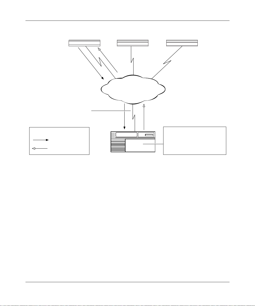
-- A frame relay PVC in group access mode refers to its BootP client
interface table to find an associated IP address for the BayStack router.
Note:
The BootP client interface table contains a data link connection
identif ier (DLCI) and IP address pair for each PVC. You use Site Manager to
create this table when you follow the instructions for setting up routing paths
in Chapter 3
.
303516-A Rev 00
For example, in Figure 1-2, the BayStack router sends BootP requests for
its IP address. The upstream rout er receives the reque st on PVC 31. The
upstream router deter mines the DLCI, refers to DLCI 31 in the BootP
client interface table, finds the IP address, and sends a BootP response
containing the IP address back to PVC 31.
1-7
Page 28
Configuring BayStack Remote Access
AN/ANH/ARN
Circuit containing PVC 31, 32, 33 (for
virtual connections to the three routers)
Key
BOOTP request
BOOTP response
Booting router 2 Booting router 3
PVC 32
PVC 31
Frame Relay
Upstream router
PVC 33
BOOTP Client Interface Table:
DLCI 31 192.32.1.2
DLCI 32 192.32.1.3
DLCI 33 192.32.1.4
NPA0002A
Figure 1-2. Requesting an IP Address from the BootP Server (Group Access PVC)
5.
The upstream router sends the IP address and subnet mask to the BayStack
router in a BootP response message.
6.
The BayStack router assigns the IP address a nd subnet mask to any serial
interface that receives a BootP response.
7.
The BayStack router stores the se IP addresses, along with the IP address of
the next-hop router, in RAM.
If more than one serial interface receive s a BootP response, the BayStack
router assigns an IP address to each interface.
1-8
303516-A Re v 00
Page 29
AN/ANH/ARN
Understanding Tools and Options
Obtaining the Kernel and Configuration File s
With a known IP address, the BayStack router can obtain its operating-system
kernel and conf iguration files over the network. The procedure is the same for
EZ-Install, Netboot, and Directed Netboot.
1.
The BayStack router sends a BootP request for the path names of the startup
files.
The BayStack router issues the request simultaneously through all seria l
(COM), Ethernet, and toke n ring (ARN only) interfaces that have IP
addresses. The BayStack router issues this request period ically for
approximately thr ee minutes, regardless of whether a cable is connected.
2.
A BootP server responds to the BaySt ack ro uter’s request with the directory
path names (Figure 1-3).
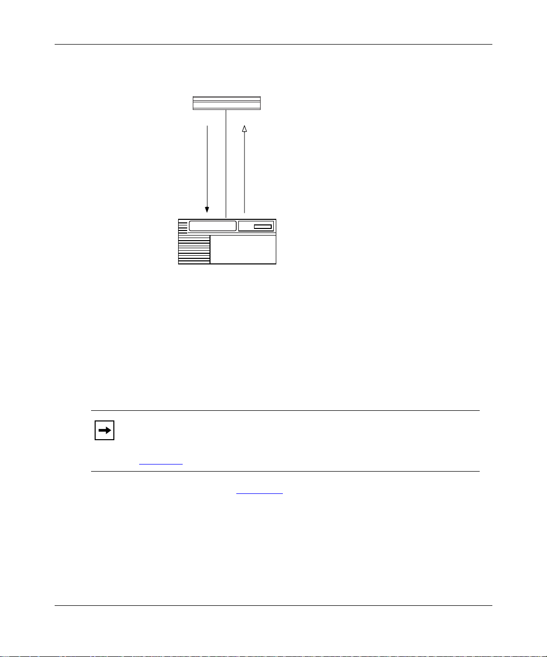
Upstream router
Pathnames
Corporate backbone
BOOTP
server
Key
BOOTP request
BOOTP response
Figure 1-3. Obtaining the Path Nam es of the Kernel and Configuration Files
The first router interfac e that processes the BootP response acts as the TFTP
client in the remaining ste ps.
3.
The BayStack router stops sending BootP requests.
303516-A Rev 00
NPA0003A
1-9
Page 30
Configuring BayStack Remote Access
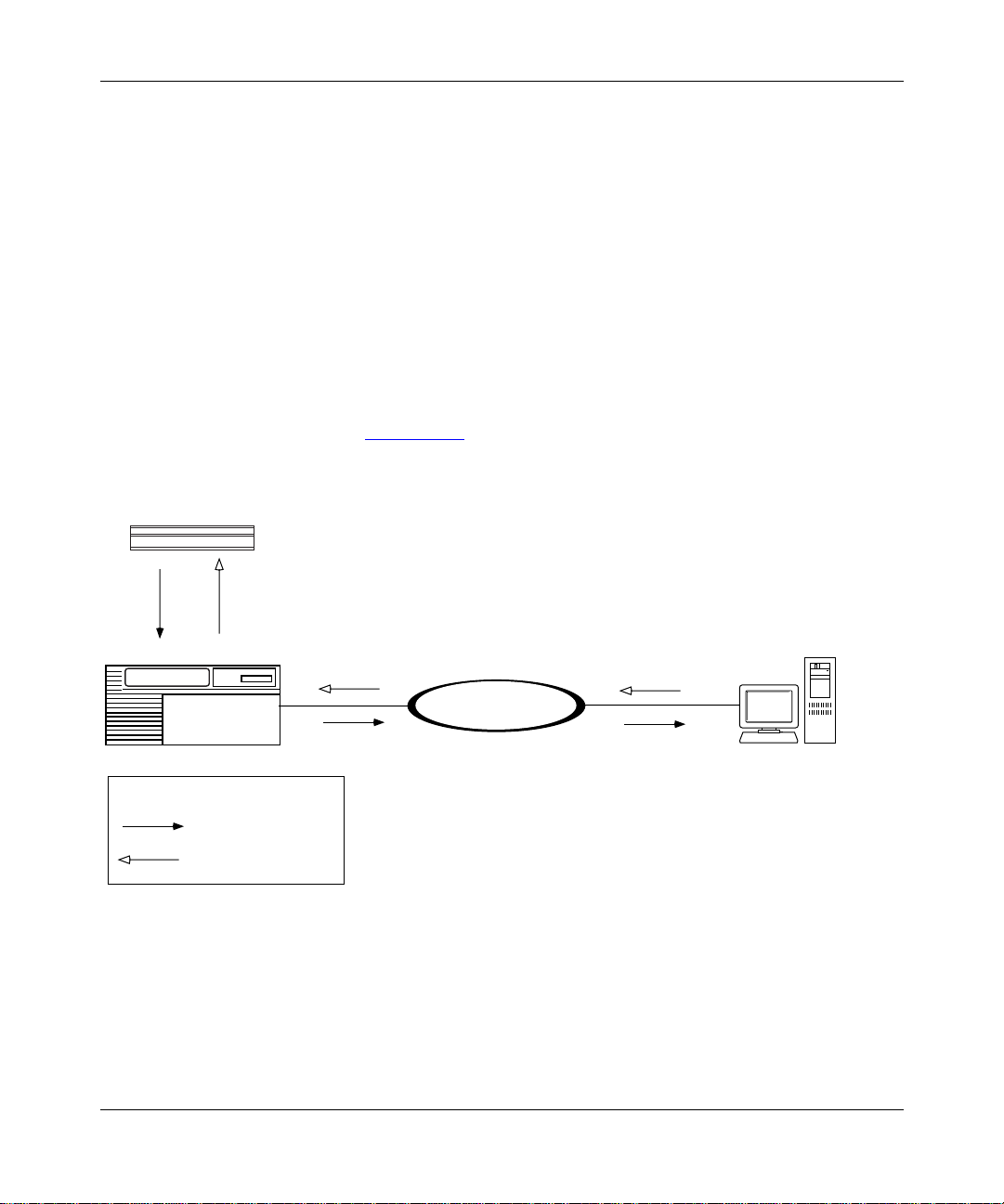
4.
The BayStack router sends a TFTP request for the configuration file.
5.
The BootP server uses TFTP to transfer the configuration file (Figure 1-4).
AN/ANH/ARN
Configuration file
Corporate backbone
Upstream router
Key
TFTP request
TFTP transfer
Figure 1-4. Obtaining the Configuration File
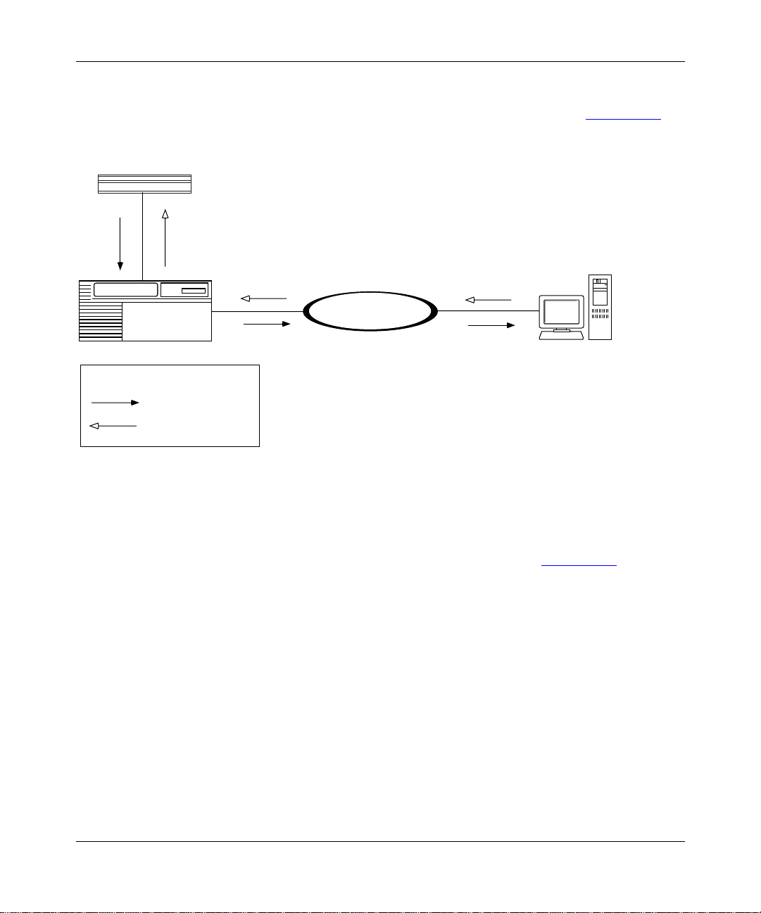
6.
The BayStack router sends a TFTP request for the kernel file.
7.
The BootP server uses TFTP to transfer the kernel file (Figure 1-5).
BOOTP server
BOOTP response
NPA0004A
1-10
303516-A Re v 00
Page 31
Understanding Tools and Options
AN/ANH/ARN
Kernel
Corporate backbone
Upstream router
Key
TFTP request
TFTP transfer
Figure 1-5. Obtaining the Kernel File
8.
The BayStack router boots the kernel.
9.
The BayStack router uses TFTP to obtain application and string files a s it
needs them.
10.
The BayStack router beg ins bridging and routing network traffic as specified
in the configur at ion file.
The BayStack router can continu e to request files, even after it begins bridging
and routing traffic.
If a failure occurs in steps 1 through 8, the BayStack router attempts to boot
locally.
BOOTP server
NPA0005A
303516-A Rev 00
1-11
Page 32

Configuring BayStack Remote Access
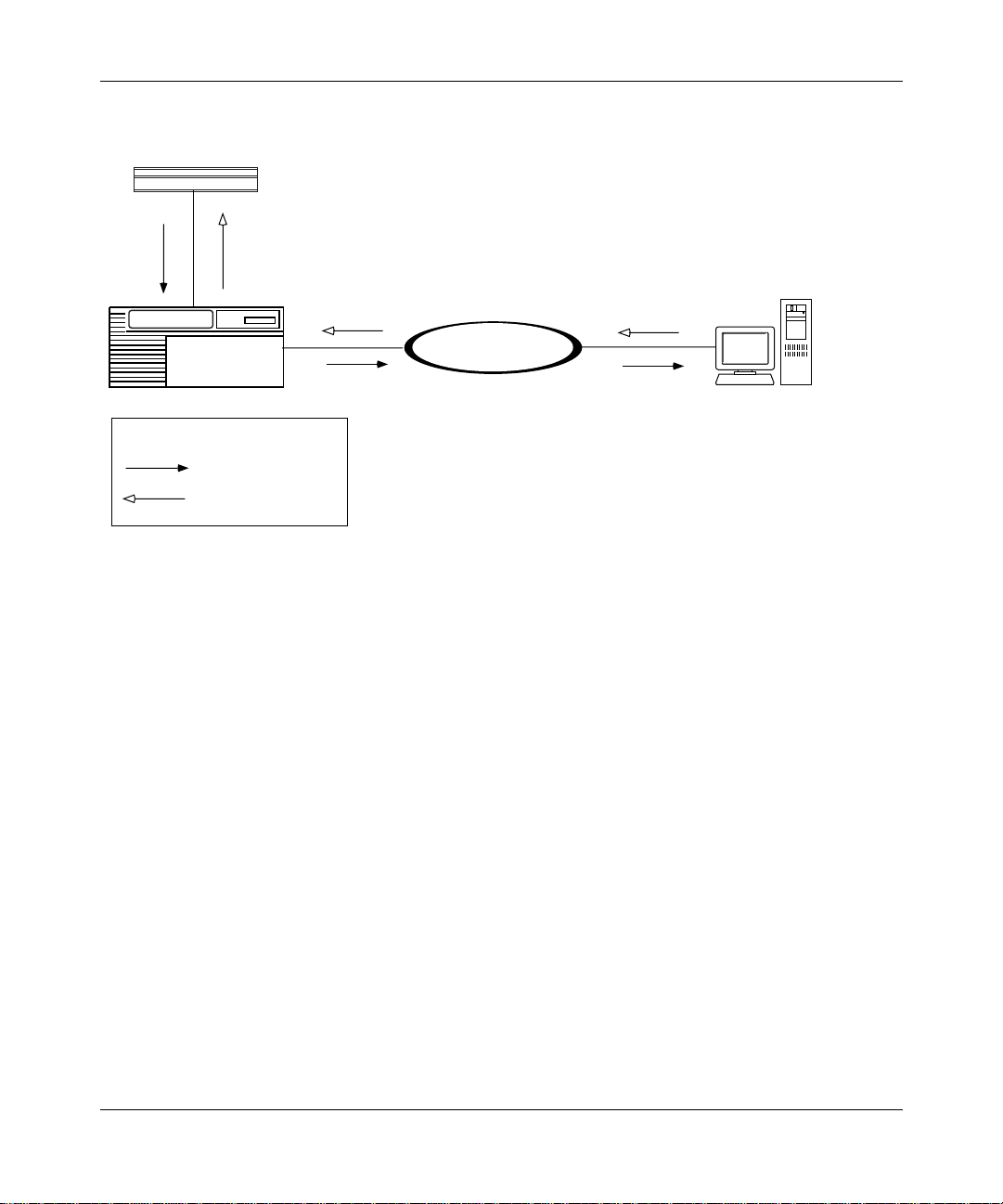
Local Boot Process
When the BayStack ro uter boots l ocall y, it reads the kernel, appli cati on, and s tring
files embedde d in the an.exe or arn.exe software image file on the local PCMCIA
flash memory card.
When you use Local Boot as the initial boot option, you boot a default (generic)
configura tion file. You must then run the Quick-Start insta llation script to
customize the de fault co nfi guration file. Running the installa tion script e stabli shes
an IP network interface between the BayStac k router and a Site Manager
workstation (Figure 1-6)
IP address = 192.32.10.12
Site Manager
workstation
.
Corporate IP network
1-12
ASCII console or PC
Console port
AN/ANH/ARN
Ethernet port
IP address = 192.32.156.7
Subnet mask = 255.255.255.0
Figure 1-6. Establishing an IP Network Interface
NPA0006A.EPS
303516-A Re v 00
Page 33

Appendix C, “Using the Quick-Start Local B oot Procedure briefly describes the
procedure for customiz ing the default configur a tion file, provides worksheets for
preparing to run the procedure, and explains how to begin the Quick-Start
installation script.
Prepari ng for th e Initial Startup
The first time you turn on the BayStack router, it begins a startup procedure to
obtain the fi les it ne eds to ope rate routin ely ov e r the netw ork. Fo r the proc edure to
be successful, you must first complete the following tasks:
• Select the initial startup option (see the next section,“ Selecting the Initial
Startup Option”)
Understanding Tools and Options
• Set up the network to support the start up option (see Chapter 3
• For options other than EZ-Install, configure the BayStack router for the
startup option (see Chapter 4
• Provide a tailored conf igura tion fi le for the BayStack router (see “Providing a
Tailored Configuration File” on page 1-15)
• Coordinate the initial startup with a person at the BayStack router sit e
The person at the BayStack router site installs the hardware and cable s, and
then initiates the appropriate startup option. The BayStack ro uter hardware
installation guide explains these ta sks in detail.
As an alternative to anothe r pe rs on perfo r ming the initial startup at the
Note:
BayStack router site, you can perform these tasks using a modem connection.
Selecting the Initial Startup Option
By default, the EZ-I nstall procedur e begi ns whe n you tur n on t he BayStack r outer.
You can change the initial startup option to Local Boot or Netboot.
)
)
303516-A Rev 00
1-13
Page 34

Configuring BayStack Remote Access
This section reviews the options for initial startup and lists the requirements for
each startup opt ion. “ Selec ting the Routine Start up Opt ion ” on p age 1-16 provides
similar informatio n for routine operati on. “Steps for Completing Startup Options
on page 1-18 describes the procedure for configuring a startup option.
Even if you use the default option, EZ-Install, Bay Networks strongly
Note:
recommends that you c onnect a modem or a console to t he BayStack r outer for
initial startup. With a console connection, you can issue commands to the
BayStack router and displa y messages. This is ver y useful if you hav e network
problems after installation.
EZ-Instal l
EZ-Install is the easi est option for the person at the BayStack router site to
perform, becau se the BayStack ro ute r au tom at ically begins the procedure at
startup, and the network a utomatically supplies the IP address and configuration
file.
The EZ-Install procedur e requires the following at ini tial startup:
• A communications link between the BayStack ro uter and an upstream route r
over an HDLC or frame relay interface
”
1-14
• A BootP server that contains a custo mized conf igura tion f ile for the BayStack
router
If EZ-Install fails in an initial startup attempt, one of the following occurs:
• An AN or ANH router attempts to boot once using the Local Boot option. If
both boot attempts fail, you must troubleshoot the problem and reboot the
router as described in Appendix B, “
Trouble shooting Network Boot
Problems.
• An ARN router first tries to local boot, and then tries to netboot. The ARN
continuously a ttempts t o l ocal boot and netbo ot un til it boots suc cessf ully, you
turn off the ARN, or you interr upt the process in one of the following wa ys:
-- Press the Reset button on the ARN back panel
-- Type the [Control]-c break sequence at the management console
303516-A Re v 00
Page 35

Understanding Tools and Options
Local Boot
The Local Boot procedure requires the following at initia l startup:
• An installed PCMCIA flash memory card that conta ins the software image
file and a generic configuration file
• A local console or modem connection with the BayStack router
When you use Local Boot as the initial boot option, the Site Manag er connection
is not yet in place. The BayStack router boots using the generic conf iguration file;
then, you must run the Quick-Start ins tallation script to customize the
configura tion file and save it locally (see Figure 1-6
on page 1-12).
See the description of the Quick-Start installation procedure in Appendix C,
“Using the Quick-Start Local Boot Proc edure .
Netboot
The Netboot procedure requir es the following at initia l sta rtup:
• A communications link between the BayStack ro uter and an upstream route r
over an Ethernet, HDLC, frame relay, or token ring (ARN only) interface
• A local console or modem connection with the BayStack router
• A BootP server that contains the software image file (arn.exe for the ARN or
an.exe for the AN/ANH) or a network configuration file (config) customized
for the BayStack router
• An IP address assigned to the BayStack router’s boot interface
Providing a Tailored Configuration File
Since the BayStack r outer ships with a generic configuration f ile on the PCMCIA
flash memory card, you must tailor that file to your network before the BaySt ack
router can bridg e and ro ute traffic.
You can provide the BayStack router with a tailored configuration file during the
initial startup in one of the following ways:
• Place a tailored configuration file on the server for the BayStack router to
download dur ing EZ-Install or another netboot procedure.
See “Preparing Configuration and Image Files
about creating a tailored configuration file.
303516-A Rev 00
” in Chapter 3 for information
1-15
Page 36

Configuring BayStack Remote Access
• Allow the BayStack router to start using the generic configuration file during
a Local Boot procedure; then, use the Technician Interface Quick-Start
installation scri p t to configu re o ne or mo re interfaces for IP so that the
BayStack router can connect to Site Manager (or another network
management tool).
The Quick-Start procedure initially tailors the default configuration file; use
Site Manager to complete the configuration. See Appendix C
information.
Selectin g the Ro utine Startup Option
This section provide s information to help you select the boot conf iguration for
routine startup operations.
Recommendations
Bay Networks recommends that you do the following:
• Maintain the complete softw are image f ile (an.exe or arn.exe) on the local file
system at all times, in case the netw ork connection to the BootP server goes
down and the BayStack router needs to use Local B oot for startup.
for more
Netboot
1-16
• Set up the network to support Netboot even if you plan to use the Local Boot
option. With the network set up to support Netboot, you can boot the
BayStack router ov er the network for some procedures and boot it locally for
others.
Netboot takes longe r than the other startup options, but has many benefits.
Over a low-speed WAN, or after configuring the BayStack router to run
Note:
several protocols, netbooting can take up to 15 minutes. It takes less time to
netboot only the kernel file or configur ation file.
Using Netboot for routine sta rt ups allows you to:
• Manage software image and configuration files from a remote location by
storing them on the BootP server
303516-A Re v 00
Page 37

Understanding Tools and Options
This option greatly simplifies the management of remote routers by allowing
you to keep the sta rtup files up-to-date in a single loc ation -- the BootP server.
• Minimize the need to maintain the BayStack router’s local file system
When the BayStack router obt ain s files from a BootP server, it stores them in
memory, not in its file system, reducing the need for frequent file-s ystem
compactions. (See Using Technician Interface Software or Configuring and
Managing Routers Using Site Manager to learn about compacting a file
system.)
• Restore a corrupted file system
The BayStack router’s file system resides on an installed flash memory car d.
With Netboot enabled, the BayStack router can still boot over the network if
the local fil es become corrupted. (When the BayStack router rebo ots due to a
reset or power loss, it automatically boots the configuration and image files
over the network if it cannot find intact files locally.)
• Obtain application and string files from the BootP server as the BayStack
router needs them
Obtaining these f iles individually, rather than obtaining the entire an.exe or
arn.exe file, reduces line costs and the use of flash memory space.
The Netboot procedure requir es the following at initia l sta rtup:
• A communications link between the BayStack ro uter and an upstream route r
over an Ethernet, HDLC, frame relay, or token ring (ARN only) interface
• A local console or modem connection with the BayStack router
• A BootP serve r t hat c ontains th e operati ng- system k erne l (krnl _arn. exe for the
ARN or krnl_an.exe for the AN/ANH) or a network configur at ion file
customized for the BayStack router
• An IP address assigned to the BayStack router boot interface
Directed Netboot
The Directed Netboot procedur e requires the following at ini tial startup:
• A communications link between the BayStack ro uter and an upstream route r
over an Ethernet, HDLC, frame relay, or token ring (ARN only) interface
• A local console or modem connection with the BayStack router
303516-A Rev 00
1-17
Page 38

Configuring BayStack Remote Access
• A TFTP server that contains the ke rnel file (krnl_arn.exe for the ARN or
krnl_an.exe for the AN/ANH) or a network configuration file customized for
the BayStack router
Compared with Netboot, Directed Net boot offers the following advanta ges:
• Creates less network traffic
• Is generally faster
Directed Netboot is usually reserved for starting the BayStack route r after the
initial startup be cause you need to know the exact locat ion of the startup files.
During Directed Netboot , the BayStac k router transfers fil es from a TFTP server
directly, bypassing negotiation with a BootP server for the IP address and path
names of the startup fi les.
Local Boot
Local-booting the star tup files for routine startups allows you to:
• Minimize the time it takes the BayStac k router to boot
In most configura tions, however, the difference between the two options is
only a few seconds. Typically, local-booting takes two to three minutes.
• Minimize line usage
Obtaining files locally prevents an increase in network traffic during the
startup process.
When you choose the Local Boot option for routine startups, the BayStack router
reads the IP addresses from the local configuration file and assigns them to the
appropriate interfaces.
Steps for Completing Startup Options
This section summarizes the steps fo r completing these startup options:
• EZ-Install
• Netboot
• Directed N etboot
• Local Boot
1-18
303516-A Re v 00
Page 39

EZ-Install
Understanding Tools and Options
You can use Netboot for so me pr ocedures a nd Lo cal Boot for othe rs, p rovid ed you
have set up the network to support Netboot.
To boot the BayStack router over the network, all rout ers in the path to
Note:
the BootP server must be running BayRS Version 7.60 or later.
Complete the follo wing steps for the EZ-Install option:
1.
Use the Configurat ion Manager in local mode to create a complete
configuration file for the BayStack router. (See Chapter 3 and Configuring
and Managing Routers with Site Manager.)
2.
Set up a UNIX workstation on the network to support BootP. (See Chapter 2.)
3.
Create a BootP clie nt on the upst ream router to su pport autom ated addr essing ,
and configur e all rout ers betwe en the BootP serv e r and the BayStack r outer as
BootP relay agents. (See Chapter 3.)
4.
Ensure that there is a network connection from a synchronous interface on the
BayStack router to the upstream router.
If the BayStack route r will connect to the upstream router over a frame
Note:
relay circ uit, ensure that the upstream router is running BayRS Version 7.80 or
later.
5.
A person at the BayStack router site install s and turns on the router. (See the
model-specific hardware installation guide.)
The BayStack router obta ins a softwa re image from its loc al f ile system, an IP
address from the upstream router, and the customized configuration file f rom
the BootP server. (“The Boot Process
” on page 1-5 describes this process; no
action is required.)
If the configur ation file meets your networ k requir ements, the BayStack
router starts bridging and routing traffic.
6.
Use the Site Manager Statistic s Manager and Events Manager tools to verify
that the BayStack ro uter is rou ting traffic as specified in the confi gur ation f ile .
(See Configuring and Mana ging Route rs with Site Manager.)
303516-A Rev 00
1-19
Page 40

Configuring BayStack Remote Access
Netboot
Complete the follo wing steps for the Netboot option:
1.
Use the Configurat ion Manager in local mode to create a complete
configuration file for the BayStack router. (See Chapter 3 and Configuring
and Managing Routers with Site Manager.)
2.
Set up a UNIX workstation on the network to support BootP. (See Chapter 2.)
3.
Use Site Manager to enable BootP on each router interface between the
BayStack router and the BootP server. (See Chapter 3
4.
Ensure that there is a network c onnection from a synchronous, Ethernet, or
token ring (ARN only) inte rface on the BayStack router to the upstream
router.
If the BayStack route r will connect to the upstream router over a frame
Note:
relay circ uit, ensure that the upstream router is running BayRS Version 7.71 or
later.
5.
Install the kerne l and applic ation files in the BootP server’s file system, and
make sure that they res ide in the sa me direc tory. (See Chapter 2.)
.)
1-20
6.
The person at the BayStack router site establishes a Technician Interface
session, or you establish a session using a modem. (See the hardware
installation guide.)
7.
The person at the BayStack router console uses the
bconfig
and
ifconfig
commands to configure a synchronous, Ethernet, or token ring (ARN only)
interface. ( See Chapter 4 and the hardware ins tallation guide. )
8.
The person at the BayStack router site boots the router. (See the hardware
installation guide.)
After the BayStack router boots, it obtains at least one startup file from the
BootP server. If the configuration file meets your network requirements, the
BayStack router starts bridging and routing traffic.
9.
Use the Site Manager Statistic s Manager and Events Manager tools to verify
that the BayStack ro uter is rou ting traffic as specified in the confi gur ation f ile .
(See Configuring and Mana ging Route rs with Site Manager.)
303516-A Re v 00
Page 41

Directed Netboot
Complete the follo wing steps for the Directed Netboot option:
1.
Use the Configurat ion Manager in local mode to create a complete
configuration file for the BayStack router. (See Chapter 3 and Configuring
and Managing Routers with Site Manager.)
2.
Set up a network server to support TFTP. (See Chapter 2.)
3.
Install the BayStack route r image and/or configuration files in the TFTP
server’s file system. (See Chapter 2
4.
Ensure that there is a network c onnection from a synchronous, Ethernet, or
token ring (ARN only) inte rface on the BayStack router to the upstream
router.
Note:
relay circ uit, ensure that the upstream router is running BayRS Version 8.00 or
later.
Understanding Tools and Options
.)
If the BayStack route r will connect to the upstream router over a frame
5.
The person at the BayStack router site establishes a Technician Interface
session, or you establish a session using a modem. (See the hardware
installation guide.)
6.
The person at the BayStack router console uses the
bconfig
and
ifconfig
commands to configure a synchronous, Ethernet, or token ring (ARN only)
interface. ( See Chapter 4
7.
The person at the BayStack router site boots the router. (See the hardware
and the hardware instal lation guide.)
installation guide.)
The BayStack router obtains one or more start up files from the TFTP serve r.
If the configur ation file meets your networ k requir ements, the BayStack
router starts bridging and routing traffic.
8.
Use the Site Manager Statistic s Manager and Events Manager tools to verify
that the BayStack ro uter is rou ting traffic as specified in the confi gur ation f ile .
(See Configuring and Mana ging Route rs with Site Manager.)
303516-A Rev 00
1-21
Page 42

Configuring BayStack Remote Access
Local Boot
Complete the follo wing steps for the Local Boot option:
1.
Complete the Quic k-Start configuration worksheets. (See Appendix C,
“Using the Quick-Start Local Boot Proc edure .)
2.
The person at the BayStack router site establishes a Technician Interface
session, or you establish a session using a modem. (See the hardware
installation guide.)
If you are not at the BayStack router console, pro vide the person at the
console with the information in the configuration worksheets. The hardware
installation guide contains duplicate worksheets. (See Appendix C, “
the Quick-Start Local Boot Proced ure.)
3.
The person at the BayStack router console runs the installation scri pt
(install.bat for the AN/ANH and inst_arn.bat for the ARN), using the
information provided in the worksheets you completed in step 1. (See
Appendix C, “
installation guide.)
4.
The installation sc ript records the responses in a configuration file.
(See Appendix C, “Using the Quick-Start Local Boot Procedure and your
hardware instal lation guide.)
Using the Quick-Start Local Boot Procedure and your hardware
Using
1-22
If the configur ation file meets your networ k requir ements, the BayStack
router starts bridging and routing traffic.
5.
Use the Site Manager Statistic s Manager and Events Manager tools to verify
that the BayStack ro uter is rou ting traffic as specified in the confi gur ation f ile .
(See Configuring and Mana ging Route rs with Site Manager.)
303516-A Re v 00
Page 43

Chapter 2
Setting Up a UNIX Boot Server
To support network booting, you need to set up a UNIX workstation on the
network to run BootP and TFTP. This chapter de scribes what you need to do at a
UNIX workstation to prepare for booting BayStack routers over the network.
Topic Page
Setting Up a BootP Server
Setting Up a TFTP Server 2-8
What to Do Next 2-12
2-2
When a BayStack router boots ov e r the network, it obtains one or more of its
startup files from a UNIX server. When the BayStack router uses EZ-Install or
Netboot, the se rver supplies startup file path names using BootP. The router then
retrie ves the f ile s us ing TFTP. When the BayStack router uses Directe d Netboot , i t
already know s the path names of the files it needs and retrieves the files directly
from the server using TFTP.
Complete the appropriate sections of this chapter for the startup option you are
configuring:
T o Configure This Startup Option Complete These Sections
EZ-Install • Set ting Up a BootP Server
• Setting Up a TFTP Server
Netboot • Set ting Up a BootP Server
• Setting Up a TFTP Server
Directed Netboot • Set ting Up a TFTP Server
303516-A Rev 00
2-1
Page 44

Configuring BayStack Remote Access
Setting Up a BootP Server
T o su ppor t EZ-Insta ll or Netboot, th e BaySt ack rout er needs a netw ork co nnection
to a BootP server. Y ou configure a UNIX workstation a s a BootP serv er by:
• Setting up BootP sockets
• Configuring the BootP Daemon (BootPD)
Setting Up BootP Sockets
A socket is a UNIX mechanism for creating virtual connections between
operating-sys tem and network processes. For each socket, the /etc/service s file
must include a User Datagram Protocol (UDP) descriptor that provides
process-to-process addressing information.
To set up the send and receive sockets for BootP:
Log in to the UNIX workstation as
1.
Use a text editor to insert the following two lines in the
2.
bootps 67/udp # bootp server
bootpc 68/udp # bootp client
Configuring BootPD
A daemon is an unattended process (that is, one that runs in the background). An
application typically calls a daemon to perform a standard routine or service (in
this case, BootP).
Complete the follo wing tasks to configure BootP D on a UNIX workstation:
• On Sun workstations, copy the BootPD progra m to the /etc directory.
• Set up BootPD to run.
• Set up BootPD to respond to BayStack routers.
Copying BootPD on Sun Workstations
Depending on the operating system you use, Bay Networks may or may not ship
BootPD with the Site Manager package.
root
.
/etc/services
file :
2-2
303516-A Re v 00
Page 45

Setting Up a UNIX Boot Server
The AIX and HP-UX operating systems include BootPD. SunOS and Solaris do
not include BootPD, so Site Manager automatic ally installs BootPD on Sun
workstations running these operating systems.
Copy the bootpd file to the /etc directory as follows:
Log in to the UNIX workstation as
1.
Enter the following command:
2.
cp /usr/wf/ bi n/ bootpd /etc
root
.
Setting Up BootPD to Run
To configure your workstation to run BootPD when it recei ves a BootP request
packet:
As
1.
Make sure that no other line in the file begins with
2.
, use a text editor to open the
root
/etc/inetd.conf
file.
bootps
.
If there is such a line, your workstation is already configured as a BootP
server. Comment out this line by typing a pound sign (#) at the beginning of
the line so that the serve r will use the BootPD program that you spe cify in the
next step.
Insert the fol lowing line anywhere in the file to configure your
3.
workstation as a BootP server:
bootps dgram udp wait root /etc/bootpd bootpd
Save and exit the file.
4.
303516-A Rev 00
Setting Up BootPD to Respond to BayStack Routers
When the operating system receives a BootP request packet, it starts BootPD.
BootPD matches the source IP address of the packet to an IP address in its B ootP
table (bootptab file) to determine the path names of the request ed st artup files.
Note:
The bootptab file can include the same path name for all booting
routers, or a different path name for each IP address.
Entries in bootptab also include opt ional paramete r tags. Bay Ne tworks sup plies a
sample bootptab file tha t Site Manager installs automaticall y in the /usr/wf/config
directory. Use a copy of this sample file if you do not already have a bootptab file.
2-3
Page 46

Configuring BayStack Remote Access
To set up BootPD to respond to booting routers:
As
1.
contains a
view the contents of the
,
root
bootptab
file.
directory to determine if it already
/etc
If it does contain a bootptab file, skip steps 2 and 3 and proceed to step 4 to
edit this file.
Enter the following command to copy the
2.
bootptab
file to the
/etc
directory:
cp /usr/wf/config/bootptab /etc
Use a text editor to open the
3.
4.
In the
bootptab
file, type the information that pertains to the BayStack
bootptab
file in the
directory.
/etc
routers in your network.
The section that follows explains how to format your entries. Use Tables 2-1
and 2-2 to determine which tags and values you need. Figure 2-1 shows the
sample bootptab file included with the Site Manager software. The comments
in this file explain the sample definitions.
Save the
5.
Note:
The bootptab f ile must reside in the /etc director y. BootPD fails if it
bootptab
file changes.
cannot find the bootptab file in /etc.
2-4
Editing the bootptab File
Specify a hostname definition in the bootptab file for each Ba ySt ack rou te r in
your network. The format of each definition in the bootptab file is as follows:
<
hostname
:
<tg>=<value>
:
<tg>=<value>
:
<tg>=<value>
•
hostname
client). Each
>:\
:\
:\
:
is a name you assign to a BootP client (each BayStack router is a
hostname
definition must:
-- Contain a maximum of 79 characters
-- Contain alphanumeric characters, and an alphabetic f irst character
-- Not contain an underscore (_)
303516-A Re v 00
Page 47

Setting Up a UNIX Boot Server
• You can use a dot (.) to separate characters, but the character immediately
following the dot must be alphabetic.
is a BootP parameter name (tag).
•
tg
• Follow each tag with an equals sign (=) and a value.
• A pound sign (#) at the beginning of a line indicate s a comment.
• A backslash (\) at the end of a line indicates continuation of the line.
Note:
Make sure you type a backslash (\), not a slash ( /), at the end of each
line that does not conclude a definition.
Table 2-1
lists the BootPD tags for router host names. Table 2-2 lists the BootPD
tags for kernel file names.
Table 2 -1 . Boo tPD Tags for a Router Host N am e
Required or
Tag
ip Required IP address -- the host IP address
sm Optional Subnet mask -- the host subnet
T129 Required Path name of the router
T130 Required Size of the router c onfiguration file
tc Optio nal Table continua tion -- a poi n ter to
Optional Value Example
of the router
mask of the router
configuration file. The maximum
length is 49 character s.
in 512-byte blocks. This tag
determines how much memory the
router allocates for the file. Set this
tag to 0x0004.
another location in the same file
for addit ional information. This tag
points to information that is
common to all routers that use
BootPD . If the informatio n
contradict s information in a
specific host-name definition,
BootPD uses the information in
that definiti on.
ip=192.32.5. 2
sm=255.255.255.0
T129="/usr/cfg/
an_Bost.cfg"
T130=0x0004
tc=general
303516-A Rev 00
2-5
Page 48

Configuring BayStack Remote Access
Table 2 -2 . Boo tPD Tags for a Kernel File Nam e
Required
Tag
or Optional Value Example
hd Required Home directory -- the directory on
the workstation containing the
kernel files. By default, the Image
Builder writes its files to the
directory specifi ed in the exampl e.
rel<number>
The
contains the current BayRS
release. If you change the default
or move the files to another
directory, specify that directory .
bf Required Boot file -- the name of the kernel
file.
bs Required Boot size
file in 512-byte blocks. If you
specify
server calcul ates the size of the
file for each BootP request.
vm Required V endor magic cookie selector
the BootP server should al ways
reply in a manner compliant with
RFC 1048. You must specify
rfc1048
BayStack router to understand the
BootP responses it receives.
auto
for this tag in order for the
direc t o ry
-- the size of the kernel
as the size, the Boot P
--
hd=/$HOME/.bui lder_dir/
rel120/an
bf=krnl_an.e xe
bs=auto
vm=rfc1048
2-6
The sample bootptab file shown in Figure 2-1 enables two ANs (named
AN.Boston and AN.Chicago) to boot over the network. Use the basic format
shown in Figure 2-1
to set up your own bootptab file.
Verifying Consistent BootP Service
You may want to configure a second workstation as a BootP server for backup
purposes. If you do so, make sure that the two bootptab files are identical. Also,
make sure that the kernel, appl ication, and string files are from the same BayRS
version.
303516-A Re v 00
Page 49

Setting Up a UNIX Boot Server
# This file contains the default specification for the boot
# image file to be used by all ANs.
# "general" contains information that is common to all ANs
# that need to boot via BOOTP. You can use any word in place
# of "gener al ."
genera l: \
# "hd" specifies that /$HOME/.builder_dir/rel900/an is the
# directory on the workstation where the boot files are
# located. By default, the Image Builder writes its files to
# this directory. If you are using a router software version
# later than 8.00, add the associated three digits to the end
# of the "rel" directory name. If you moved the files to
# another directory, specify that directory.
:hd=/$HOME/.builder_dir/rel812/an:\
# "bf" specifies that the name of the boot image kernel file
# is krnl_an.exe.
:bf=krnl_an.exe:\
# "bs" indicates the size of the boot file. If you specify
# "auto" as the size, the BOOTP server calculates the size of
# the file for each BOOTP request.
:bs=auto:\
303516-A Rev 00
# "vm" indicates that the BOOTP server should always reply in
# a manner compliant with RFC 1048. You must enter rfc1048
# for this tag so that the AN can understand the BOOTP
# responses it receives.
:vm=rfc1048:
# This line mark s the beginning of the active definition for
# the AN we are naming "AN.Boston."
AN.Boston:\
# "ip" indicates the IP address of the AN.
:ip=192.32.5.2:\
# "T130" indicates the size of the AN’s configuration file in
# 512-byte blocks. Always use 0x0004.
:T130=0x0004:\
# "T129" indicates the pathname of the configuration file
# for the AN.
:T129="/usr1/cfg/AN_Bost.cfg":\
2-7
Page 50

Configuring BayStack Remote Access
# "tc" indicates that the "general" definition contains more
# information that applies to BOOTP transmissions to
# "AN.Bo sto n. "
:tc=ge ne ral :
# This is the active definition for the AN we are naming
# "AN.Ch ica go ."
AN.Chi ca go: \
:ip=10 .0 .0. 4: \
:T130= 0x 000 4: \
:T129= "/ rte 3/ cfg/AN _C hi c. cfg ":\
:tc=ge ne ral :
Figure 2-1. Sample bootptab File
Setting Up a TFTP Server
The BayStack router needs a network connection to a TFTP server to complete
EZ-Install, Netboot, or Directed Netboot. You configure a UNIX workstation as a
TFTP server by:
• Setting up the TFTP daemon (TFTPD) to provide TFTP access
• Setting up static routes to BayStac k routers (optional)
• Loading the changes into memory
Setting Up TFTPD
When you set up the TFTPD server on a UNIX workstation, you can allow TFTP
access to the root directory and any subdirectory, or restrict TFTP access to a
specified directory or path name.
Allowing TFTP acces s to all directories is the simpler procedure. Specifying a
directory provides security, but requires eithe r keeping the startup files in the
specified directory or creating a link to each path name.
2-8
303516-A Re v 00
Page 51

Setting Up a UNIX Boot Server
Providing TFTP Access to All Directories
To provide TFTP access to files in the root (/) directory and all subdirectories,
insert the appropriate line for your operating system in the /etc/inetd.conf file .
Find the sample line for your operating system in Table 2-3
Table 2-3. Providing TFTP Access to All Directories
Operating
System Sample Line to Insert in /etc/inetd.conf File, or Other Instruction
.
SunOS
Solaris
HP-UX
AIX Use the System Management Interface T ool (SMIT) to configur e TFTP. For
tftp dgram udp wait root /usr/etc/in.tftpd in.tftpd -s /
tftp dgram udp wait root /usr/sbin/in.tftpd in.tftpd -s /
tftp dgram udp wait root /etc/tftp tftp
instructions, see the IBM guides on TCP/IP daemons and TFTP.
Restricting TFTP Access to Specified Directories
To restrict TFTP access to a specific directory:
Log in to your UNIX workstation as
1.
Insert the appro pr iate line i n the
2.
The examples in Table 2-4
restrict access to the /tftpboot directory. You can
root.
/etc/inetd.conf
file.
substitute any directory you want.
Table 2-4. Restricting TFTP Access to Specified Directories
Operating
System Sample Line to Insert in /etc/inetd.conf File, or Other Instruction
SunOS
Solaris
HP-UX
AIX Use the System Management I nterface Tool (SMIT) to configure TFTP.
tftp dg ram udp wai t ro ot /u sr/e tc/i n.tft pd in .tft pd - s
/tftpb oot
tftp dgram udp wait root /usr/sbin/in.tftpd in.tftpd
-s /tft pb oot
tftp dgram udp wait root /etc/tftp tftp -s /tftpboot
For instructions, see the IBM guides on TCP/IP daemons and TFTP.
303516-A Rev 00
Create a symbolic link in the specified directory for every startu p file
3.
path name.
2-9
Page 52

Configuring BayStack Remote Access
For example, to set up symbolic links in the /tftpboot directory:
Enter the following command to move to the
a.
cd tftpboot
Note:
Do not insert a slash (/) in the
cd tftpboot
/tftpboot
command. A symbolic link
directory:
cannot contain refere nces to directories above the directory specified in the
tftpd
command line.
Enter the following commands to create symbolic links:
b.
ln -s . usr
ln -s . tftpboot
Adding a TFTP User for an HP 9000 Workstation
Follow the instructions in this section only if you are running Site Manager on an
HP 9000 workstation.
To add a TFTP user for the HP 9000, insert the following line in your /etc/passwd
file. Bay Networks recommends that you use root (/) as the TFTP home directory.
tftp::
<user_id>:<group_no.>
::/:/bin/false
For example:
tftp::510:20::/:/bin/false
Note:
Bay Networks recommends that you not use the System Administration
Manager (SAM) utility to add a TFTP user.
Setting Up Static Routes to Next-Hop Routers
If your workstation requires static routes, read this se ction to learn how to specify
a path to the network by:
• Editing the /etc/inetd.conf file
• Verifying the routes
• Loading the changes into memory
2-10
303516-A Re v 00
Page 53

Setting Up a UNIX Boot Server
You must set up a static route for each path between the BayStack routers and the
BootP server’s next-hop router.
You may want to specify a static route in a multihop environment or in
Note:
an envi ronment using routing protocols such as RIP, where minor routing
update delays may extend the time it takes to Netboot.
Editing the /etc/inetd.conf File
Insert the following line in the /etc/inetd.conf file to set up a static route:
route add
destination
gateway
<destination> <gateway> <hops>
is the IP address of the BayStack router or its network.
is the IP address of the network destination to which packets will be
addressed.
is the number of hops to the network destination.
hops
Verifying the Routes
After adding a static rout e for each pat h to the BaySta ck routers, enter the
following c ommand to display the routing table and veri fy the rou tes you added:
netstat -r
Loading the Changes into Memory
Once you modify the /etc/ine td.conf file, you must force the operating system to
reread it by rebooting the workstation or by issuin g a hang-up sig nal.
In most cases, reboot the workst ation. Issue a hang-up signal if the workstation is
performing a task that you do not want to interrupt.
Rebooting Your Workstation
303516-A Rev 00
To reboot your workstation:
Log in as
1.
Enter the following command
2.
/etc/shutdown now -r
root.
(the
flag reboots the worksta tion)
-r
:
2-11
Page 54

Configuring BayStack Remote Access
Issuing a Hang-Up Signal
To issue a hang-up signal:
Log in as
1.
Enter the following command to hang up on the
2.
ps -aux | grep inetd
The system displays a line simila r to this one:
root 148 0.0 0.0 48 0 ? IW Sept 14 0:07 inetd
Enter the following command, using the first nu mber in the line after the
3.
word
kill -1 148
The inetd process rereads the /etc/inetd.conf file.
What to Do Next
Before you can netboot the BayStack router, complete the steps in Chapter 3.
root.
(in this case,
root
148
process:
inetd
):
2-12
303516-A Re v 00
Page 55

Chapter 3
Configuring Netboot Services with Site Manager
This chapter describes how to use Site Manager to configure netboot services for
BayStack routers in the network.
Topic Page
Preparing Configuration and Image Files
Enabling Netboot or Directed Netboot 3-6
Adding a Netboot or Directed Netboot Interface 3-8
Configuring a Netboot or Directed Netboot Interface 3-9
Setting Up Routing Pat hs for Netboot 3-10
Creating the BootP Client Interface Table 3-13
3-2
Complete the appropriate sections of this chapter for the startup option you are
configuring:
T o Configure This Startup
Option Complete These Sections
EZ-Install (default) • Preparing Configuration and Image Files
EZ-Install over Frame Relay
PVC in group-access mode
Netboot • Enabling Netboot or Directed Netboot
Directed Netboot • Enabling Netboot or Directed Netboot
• Preparing Configuration and Image Files
• Creating the BootP Client Interface Table
• Adding a Netboot or Directed Netboot Interface
• Configuring a Netboot or Directed Netboot Interface
• Setting Up Routing Pat hs for Netboot
• Adding a Netboot or Directed Netboot Interface
• Configuring a Netboot or Directed Netboot Interface
303516-A Rev 00
3-1
Page 56

Configuring BayStack Remote Access
Preparing Configuration and Image Files
The BayStack router ships with a flash memory card that contains a default
(generic) conf iguration file and the an. exe or arn.exe router software image. For
the BayStack routers in your network, you must create:
• A unique configuration file for each netbooti ng rou ter
• A uniform software image for all netbooting routers
Creating Configuration Files
To prepare network configuration files:
Use the Configuration Manager in local mode to create a configuration
1.
file for each BayStack router.
For instruct ions, see Configuring and Managing Route rs with Site Manager.
Also, see the following:
• Table 3-1
configura tion file for BayStack AN routers
• Tables 3-2
configura tion file for BayStack ARN routers.
For ARN routers, you choose base, e xpansion, and adapter modules
Note:
separately.
Site Manager ide ntifies AN and ANH routers with module names that use
mnemonic abbrevia tions for each of the router’s connectors. For example, the
module name E/T/2S identifies an AN with one Ethernet, one tok en ring, and two
serial interfaces. The module name 8ptEHub/3S/N11 DCM identifies an 8-port
ANH with a third serial interface and an RMON dat a co llec tion module (DCM)
installed.
for the Site Manager module name to use when creating a
through 3-4 for the module names to use when creating a
3-2
303516-A Re v 00
Page 57

Configuring Netboot Services with Site Manager
Table 3-1 lists the mnemonics used in AN and ANH module names.
Table 3-1. Configuration Manager Module Names for AN and ANH
Module Name Mnemonic Connector Type
E Ethernet
T T oken ring
2S Two serial
3S Three serial
BRI-S ISDN BRI with S/ T interface
BRI-U ISDN BRI with U interface
BRI-S+ ISDN BRI S/T interf ace, floating B-channel
BRI-U ISDN BRI U interface, floating B-channel
N11 DCM RMON data collection module
CSU_DSU 56/64K DSU/CSU
FT1 T1/Fractional T1
FE1 E1/Fractional E1
8pt EHub 8-port Ethernet hub
12pt EHub 12-port Ethernet hub
303516-A Rev 00
For ARN routers, you choose base, expansion, and adapter modules se para tely.
Table 3-2
lists the base module (system board) options for ARN routers. An ARN
can have only one base module.
Table 3-2. BayStack ARN Base Module Configurations
Base Module Site Manager Module Name
Ethernet Ethernet
Ethernet with DCM Ethernet/DCM
Token Ring Token Ring
100 Base-T Ethernet 10/ 100BASE-TX Ethernet
100 Base-FX Ethernet
(fiber)
100BASE-FX Ethernet
3-3
Page 58

Configuring BayStack Remote Access
Table 3-3 lists the optional expansion modules available for an ARN. An
expansion module is a parallel daughterboard installed on the base module. The
ARN base module supports only one expansion module.
Table 3-3. Ba y Stack ARN Expansion Module Configurations
Expansion Module Site Manager Module Name
Ethernet Ethernet
Ethernet with DCM Ethernet/DCM
Token Ring Token Ring
Tri-Serial TRI Serial
Ethe rnet/Tri-Ser ial Ethe rnet/TR I Ser ial
Ethernet/Tri-Serial with DCM Ethernet/TRI Serial/DCM
Token Ring/Tri-Serial Token Ring/TRI Serial
Table 3-4
lists the optional adapter modules for an ARN. An adapter module is a
serial daughterb oard install ed in the front-pane l card cage . The ARN base module
supports one or two adapter modul es.
Table 3-4. BayStack ARN Adapter Module Configurations
Adapter Module Site Manager Module Name
Serial Serial
ISDN BRI S/T ISDN ‘S/ T’
ISDN BRI U ISDN ‘U’
56/64K DSU/CSU*
V.34 Modem V34 Modem
X.25 PAD X25 PAD
FT1/T1 DSU/CSU Fractional T1
FE1/E1 G703 Fractional E1
* The ARN supports network booting over DSU/CSU interfaces only for the default
configuration, 56 Kb/s DDS lines. You cannot netboot o ver a 64 Kb/s DSU/CSU
interface.
56/64K DSU/CSU
3-4
303516-A Re v 00
Page 59

Configuring Netboot Services with Site Manager
Record the name of each configuration file and corresponding BayStack
2.
router for later reference when configuring ne twor k bo o t opti o ns.
When you name configuration files, keep the following restrictions in mind:
• Bay Networks recommends that the operational configuration file for
each router be na me d config. If a router experiences a power fai lure, it
boots from the file named config when power returns. However, the
configura tion files that you save on a BootP server for Directed Netboot
do not have to be named config because you specify the configuration file
path name (see the description of the Site Manager parameter Boot
Config Pathname on page A-3
.)
• Configuration file names must begin with an alphabetic character. The
remaining characte rs must be alphanumeric and can include an
underscore (_). You cannot use spaces.
• Configuration file names can consist of 1 to 15 characters, including a
dot (.). Bay Networks recommends that you limit file names to 8
characters to ensure that all supported operating systems can recognize
the names.
• Configuration file-name extensions are optional and must follow a file
name and a dot. Bay Networks recommends that you limit file-name
extensions to three characters.
• BootP allows a maximum of 49 characters in a path name , including
slashes, file name, optional dot, and fi le-name extension.
If the BootP server and Si te M ana g er do not res ide on the s am e
3.
workstatio n, trans fer the co nfigu ra ti on files to the Bo o tP se rver.
Preparing an Image
If you want the router to automatically boot a network-based image when starting
up (using Netboot or Directed Net boot) , use the Site Manager Image Builder tool.
To create the kernel, application, and string files for storage on the BootP/TFTP
server:
On the Site Manager workstation, open the software image file using the
1.
Image Builder tool.
For instruct ions on how to use the Image Builder, see Configuring and
Managing Routers wit h Site Manager.
303516-A Rev 00
3-5
Page 60

Configuring BayStack Remote Access
After you open the image file, the Image Builde r automatically extra cts the
kernel image file, application files, and string files.
Keep the following in mind:
• Be sure to choose the correct image (an .exe for an AN/ANH, or arn.exe
for an ARN). If you choose an image for another router typ e, you cannot
generate the correct files.
• The kernel file and all of the applica tion (.exe) f iles and string (.str) files
must be from the same software image file. If the se files are from dif ferent
software v ersions, the router may fa il to boot or may not operate properly.
If you use a different workstation as a BootP server, transfer to that
2.
workstatio n all of the files in the di re cto ry tha t con ta ins the kernel file.
The router ca nnot ne tboot unti l the ker nel file i s availa ble on the B ootP se rve r.
Enabling Netboot or Directed Netboot
By default, the router obtains the software image files from its local file system
and its configur ation file from a BootP serv er. You can use Site Manager to
display and change these settings as follows:
3-6
Site Manager Procedure
You do this System responds
1. In the Configuration M anager window,
choose
2. Choose
3. Choose
4. Choose
Protocols
Global Protocols
Net Boot
Global
.
. The Net Boot menu opens.
. The Edit Netboot Global Parameters
. The Global Protocol s menu opens.
The Protocols menu opens.
window opens.
(continued)
303516-A Re v 00
Page 61

Configuring Netboot Services with Site Manager
Site Manager Procedur e
You do this System responds
5. Set the following parameters:
Boot Image From Network
•
Boot Config From Networ k
•
• Boot Server Address
Boot Image Pathname
•
Boot Config Pathname
•
Click on
descriptions beginning on page A-2
6. Click on OK. You return to the Configuration Manager
* When you netboot a BayStack router, the value of Boot Image Pathname is the full path name of the
active image on the rem ote se rv er. When you boot a Ba yS t ac k rout er lo cal l y, the name of the ac ti v e
image (wfHwEntry.wfHwActiveImageName) appears in the form <
Note:
Help
or refer to the parameter
Instead of enabling the Boot Image From Network parameter, you can
*
.
(continued)
Site Manager enables Netboot if you
enable one or both of the first two
parameters.
Site Manager enab l es Directed Net boot if
you enab le one or both of the first two
parameters, and then specify v alues for
the remaining par am eters.
window.
volume
>:<
image name
>.
use the Router Files Manager tool to tra nsf er an upgraded image file to the
BayStack router. To do this, delete the old image f ile, compact the file system,
and copy the upgraded image file to the BayStack router. To verify that the file
transfer was successful, use the Router Files Manager to conf irm that the new
image file on the BayStack router is the same size as that on the Site Manager
workstation . F or more information about the Router Files Manager, see
Configuring and Managing Routers with Site Manager.
303516-A Rev 00
You can also use Technician Interface commands to c onf igure networ k booting, as
described in Chapter 4
Before the router can obta in files ove r the network, you m ust set up a
Note:
.
UNIX BootP server on the network, as described in Chapter 2.
3-7
Page 62

Configuring BayStack Remote Access
Adding a Netboot or Directed Netboot Interface
When you enable Netboot or Directed Netboot, you must add (and configure) at
least one BayStack router circuit as a Netboot interface. If you are using
EZ-Install, you do not need to conf igure Netboot interfaces. You can use Site
Manager to add a Netboot interface.
Site Manager Procedure
You do this System responds
1. In the Configuration M anager window,
choose
2. Choose
3. Choose
4. Choose
5. Click on
6. Set the
Click on
description on page
7. Click on OK. You return to the Netboot Interfaces
Protocols
Global Protocols
Net Boot
Interfaces
Add
Connector
Help
.
. The Global Protocol s menu opens.
. The Net Boot menu opens.
. The Netboot I nterfaces window opens.
. The Netboot Interfa ce window opens.
parameter.
or refer to the parameter
A-4.
The Protocols menu opens.
window, which shows the interface you
just added.
3-8
303516-A Re v 00
Page 63

Configuring Netboot Services with Site Manager
Configuring a Netboot or Directed Netboot Interface
You can use Site Manager to configure a Netboot or Directe d Netboot interface.
Site Manager Procedure
You do this System responds
1. In the Configuration M anager window,
choose
2. Choose
3. Choose
4. Choose
5. In the scroll bo x, choose the interface you
want to conf igure.
6. Set the following parameters:
•
•
•
•
•
Click on
descriptions beginning on page A-4
7. Click on
Note:
Protocols
Global Protocols
Net Boot
Interfaces
Connector IP Address
Connector Subnet Mask
Connector Next Hop
Connector Protocol Mas k
Connector State
Help
Apply
.
. The Global Protocol s menu opens.
. The Net Boot menu opens.
. The Netboot I nterfaces window opens.
or refer to the parameter
.
, then clic k on
Done
. You return to the Configuration Manager
If you conf igur e more than one int erface to Netboot, the first in terface to
The Protocols menu opens.
The w in dow shows th e p arameter values
for that interface.
window.
receive a reply from the BootP server will complete the Netboot process.
303516-A Rev 00
3-9
Page 64

Configuring BayStack Remote Access
Setting Up Routing Paths for Netboot
You set up the routing paths between the BootP server and the BayStack routers
by:
• Enabling each router interfa ce in the paths to the BayStack routers
• Creating a BootP relay agent forwarding table for each router in a path
• Creating a BootP client interface table for the upstream router when the
BayStack router is on a Frame Relay PVC in group access mode
Enabling Router Interfaces
You must enable BootP relay (also called BootP pass-through or gateway) on all
interface s in the paths be tween BayStack routers and the BootP serve r. For
example, you would enable BootP relay on the interfaces indicated in Figure 3-1
Booting routers
.
3-10
Enable BOOTP on
these interfaces
BOOTP server
Corporate backbone
NPA0007A
Figure 3-1. Enabling BootP Relay in a Sample Network
303516-A Re v 00
Page 65

Configuring Netboot Services with Site Manager
You can use Site Manager to enable BootP relay on an interface.
Site Manager Procedure
You do this System responds
1. In the Configuration M anager window,
click on the conn ector on which you want
to enable BootP relay.
2. Choose
3. Choose
4. Choose
5. Choose
6. Choose
7. Choose
Edit Circuit
Protocols
Add
. The Select Protocols window opens.
BOOTP
File
. The File menu opens.
Exit
. You return to the Configuration Manager
. The Circuit Definition window opens.
. The Protocols menu opens.
. The BOOTP menu opens.
The Edit Connector window opens.
window.
Creating BootP Relay Agent Forwarding Tables
You must create a BootP relay agent forwarding table fo r every router that passes
BootP traffic between the BayStack router and the BootP server.
The BootP relay age nt forwarding ta ble allows you to specify the IP interface tha t
receiv es the incoming BootP request packets, and the associated IP interface that
forwards them. You can add multiple pairs of incoming and outgoi ng interf aces to
support connections to multiple routers in your network.
303516-A Rev 00
3-11
Page 66

Configuring BayStack Remote Access
You can use Site Manager to create the BootP relay agent forwar ding table.
You do this System responds
Site Manager Procedure
1. In the Configuration M anager window,
choose
Protocols
.
The Protocols menu opens.
2. Choose IP. The IP menu opens.
3. Choose
4. Choose
BOOTP
. The BOOTP menu opens.
Relay Agent Interface Ta ble
. The BOOTP Relay Agent Interface Table
window opens. *
5. Click on
Forward I/F
(int er fa c e). The B O OTP R e l ay A g ent Forw ardin g
Table window opens.
6. Click on
Add
. The BOOTP Addresses window opens.
7. Set the following parameters:
Input IP Ad dress
•
Output IP Address
•
Click on
Help
or refer to the parameter
descriptions beginning on page A-7
.
8. Click on OK. The BOOTP Relay Agent Forwarding
Table window l ists the connector and
input IP address on the le ft, and the
connector and output IP address on the
right.
If you speci fy an IP address of an
interf ace that is not configured,
???
appears inst ead of the connector (for
example,
??? 192.32.23. 3
). If you
configure the IP address, Site Manager
displays the appropriate connector.
9. Click on
Done
. You retur n to the BOOTP Relay Agent
Interface Table window.
* Click on
parameters in the BOOTP Relay Agent Interface Table window. Make sure that the Timeout Secs.
parameter is set to the default, 0.
Help
or see
Configuring SNMP, BootP, DHCP, and RARP Services
for a description of the
3-12
303516-A Re v 00
Page 67

Configuring Netboot Services with Site Manager
Creating the BootP Client Interf ace Table
The upstream router is the booting r oute r’s next-hop router. By default, the
booting router’s synchronous interfaces automatically try to obtain IP addresses
from the upstream router. This is the EZ-Install process.
If the BayStack router using EZ-Install obtains its address from the upstr eam
router , and the upstr eam router ’s interface to the BayStack rout er is a F rame Relay
PVC in group access m ode, you must use Si te Manag er to conn ect to the upst ream
router and create a BootP cl ient interface table (in addition to a BootP relay agent
forwarding table ).
You do not need to create a BootP client interface tabl e if the Frame
Note:
Relay PVC is configured to operate in direct access mode, or if the circuit is
configured to operate with Bay Networks Standard PPP (HDLC
encapsulation).
The BootP client interface table allows you to specify and pair the IP address of
the BayStack router with the DLCI of the Frame Relay group acce ss PVC.
303516-A Rev 00
If you are using EZ-Install over Frame Relay, you can have up to 20
Note:
PVCs for a single Frame Relay interface on the upstream router. If you have
more than 20 PVCs on the Frame Relay interface, the EZ-Install process may
fail. To ensure that the process doe s not f ail, conf igure a maximum of 20 PVCs
for a Frame Rela y inte rface .
For more information about the DLCI and Frame Relay, see Configuring Frame
Relay Services.
3-13
Page 68

Configuring BayStack Remote Access
You can use Site Manager to create the BootP client interface table.
You do this System responds
Site Manager Procedure
1. In the Configuration M anager window,
choose
Protocols
.
The Protocols menu opens.
2. Choose IP. The IP menu opens.
3. Choose
4. Choose
BOOTP
. The BOOTP menu opens.
Relay Agent Interface Ta ble
. The BOOTP Relay Agent Interface Table
window opens. *
5. Click on
Clien t I/F
(interface). The BOOTP Client Interface Table
window opens.
6. Click on
Add
. The BOOTP Client Interface Address
window opens.
7. Set the following parameters:
IP Address
•
DLCI Number
•
Click on
descriptions beginning on page A-8
Help
or refer to the parameter
.
8. Click on OK. The BOOTP Client Interface Table
window lists the client IP inter face and t he
DLCI number you added.
9. Click on
Done
. You retur n to the BOOTP Relay Agent
Interface Table window.
* Click on
parameters in the BOOTP Relay Agent Interface Table window. Make sure that the Timeout Secs.
parameter is set to the default, 0.
Help
or see
Configuring SNMP, BootP, DHCP, and RARP Services
for a description of the
3-14
303516-A Re v 00
Page 69

Chapter 4
Configuring Netboot Client Services
This chapter describ es ho w t o enable a B ayStack r outer for ne tboot startup optio ns
using commands at the Technician Interface or AN Monitor prompt.
T opic Page
Using Netboot Configur ation Commands
Setting the Boot Configuration 4-3
Setting the Netboot Interface Configu ration 4-5
V erifying Your Configurati on 4-10
What to Do Next 4-11
First, read “Using Netboot Configuration Commands
” on page 4-2 for
4-2
information about wor king with som eone at a remote BayStack router site or
accessing a BayStack route r command lin e. Then, comple te the appropriate
sections of this chapte r for the BayStack router’s startup configuration:
For This Startup Configura ti o n Complete These Sections
Netboot or Directed Netboot over a
serial interface
Netboot or Directed Netboot over an
Ethernet interface
Netboot or Directed Netboot of an
ARN over a token ring int erface
• Setting the Boot Configuration
• Configuring a Serial Interface for Network
Booting
• Setting the Boot Configuration
• Configuring an Ethernet Interf ace fo r Network
Booting
• Setting the Boot Configuration
• Configuring an ARN Token Ring Interface for
Network Booting
303516-A Rev 00
4-1
Page 70

Configuring BayStack Remote Access
Using Netboot Configuration Commands
This chapter provide s instructions for using the
ifconfig, bconfig
, and
getcfg
commands to configure Netboot and Directed Netboot.
If you are not configur ing the BayStack router yourself, you can determ ine the
appropriate synta x for these commands and provide the person at the router site
with the exact command lines to use .
To access a BayStack router command line, you need a management console
connection to the router. With a terminal or modem console connec tion, you can
view router diagnostic messages and use the
ifconfig
configure Netboot and Directe d Netboot. You use
and
getcfg
bconfig
commands to
to verify a confi guration.
To display a command-line login prompt, you can do one of the following:
• Wait for the BayStack route r to local-boot (that is, wait for EZ-Install to fail).
• Interrupt the startup process by issuing a break sequence. This automatically
starts the AN Monitor, a firmware diagnostics monitor f or BayStack routers.
Be sure to issue the break sequence before EZ-Install completes.
Note:
The break sequence depends on the management c onsol e you are usi ng. Some
terminals have specific break keys; othe rs require a specific key sequence to
issue a break (for exa mple, [Control]-c or ~ #). See the documentation for
your terminal or PC terminal emulator for the correct break sequence.
4-2
To log in to either the AN Monitor or the Technician Interface, enter
Manager
at
the login prompt.
Note:
Manager
is case-sensitive; use an uppercase M.
The Technician Interface or AN Monitor command-line prompt appears. Proceed
to the appropriate section:
• Setting the Boot Configuration
• Setting the Netboot Interf ace Configuration
303516-A Re v 00
Page 71

Setting the Boot Configuration
Configuring Netboot Client Services
This section describes how to use the
option at the Technician Interface or AN Monitor command-line prompt.
• For Netboot, you use
bconfig
configura tion file or boot image (software image or kernel file) for the
BayStack router to use at startup.
• For Directed Netboot, you use
server and the full path name of the boot image and configuration files.
Using the bconfig Command Format
To configure an interface for Netboot, use the following
format:
bconfig -d [image | config
To configure an interface for Directed Netboot, use the following
command fo rm at :
bconfig [image | config
You must issue the
bconfig
boot image, and again to specify the loc ation of the configurati on file.
See Table 4-1
for a description of the
]
] [
local
|
command twice: once to specify the location of the
bconfig
command to configure a netboot
to specify the network location of a
bconfig
network
to specify the IP address of the TFTP
bconfig
[
<TFTP_host> <TFTP_pathname>
bconfig
command options.
command
bconfig
]]
303516-A Rev 00
Table 4-1 . bconf i g C omm a n d Options
Option Description
image Specif ies the BayStack router’s boot image. The boot image can be
the complete sof tware image f ile (
(
krnl_an.exe
config Specifies the BayStack router’s configuration file
local Indicat es that the specified file (
BayStack router’s local file system
network Indicates th at the specified file (
remote file system
or
krnl_arn.exe
)
an.exe
<image>
<image>
or
or
or
arn.exe
) or the kernel file
<config>
<config>
) resides in the
) resides on a
(continued)
4-3
Page 72

Configuring BayStack Remote Access
Table 4-1 . bconf i g C omm a n d Options
Option Description
<TFTP_host>
<TFTP_
pathname>
-d Re verts to the defau lt values for
Specifies the I P addr ess of t he TFTP serv er . If bot h the
<config>
host
Specifies the complete path name of
remote server
any previously specified IP address and path name for the file, thus
disabli ng Directed Netboot
files are on the n etwork, both files must reside on the same
Examples of Using the bconfig Command
1. Configure the def ault Netboot p roce dure. Boot f rom the softw are image f il e in
local flash memory and use BootP to get the configuration file from the
network.
bconfig -d im age
bconfig -d c on f ig
2. Use Netboot for both the boot image file and the configuration f ile.
bconfig image network
bconfig config network
(or
bconfig image local
(or
bconfig config network
(continued)
<image>
<image>
)
)
or
<config>
or
<config>
<image>
and nullifies
and
on the
4-4
3. Use a local configura tion file and Directed Netboot to boot the kernel file.
bconfig image network 21.3.5.62 /usr/mykernel.exe
bconfig config local
4. Boot from the local softwar e image f ile and use Directed Netboot to get the
configura tion file from the network.
bconfig image local
bconfig config network 21.3.5.62 /usr/anstartup/config
5. Use Directed Netboot for both the boot image f ile and the configurat ion file.
bconfig image network 21.3.5.62 /usr/mykernel.exe
bconfig config network 21.3.5.62 /usr/anstartup/config
303516-A Re v 00
Page 73

Configuring Netboot Client Services
Setting the Netboot Interface Configuration
This section describes how to use the
ifconfig
command to configure a BayStack
router interfa ce to support netboot options.
A BayStack router netboots over one of its serial, Ethernet, or token ring (ARN
only) interfaces. Because a router interface must have an IP address to
communicate in an IP network, the netboot interface must have a valid IP address.
You have two options for assigning an IP address to an interface:
• Configure the ups tream rou ter to sup por t automat ed add ressing f or EZ-I nstall.
Chapter 3 describes how to conf igure the upstream router to support
EZ-Install by creating the BootP client interface table. “The Boot Process” on
page 1-5 describes how the router automatically obtains an IP address during
the EZ-Install process.
• Use the
ifconfig
command to configure a serial, Ethernet, or token ring
interface for Netboot or Directed Netboot.
The following sections describe the
ifconfig
comman d form at s.
Configuring a Serial Interface for Network Booting
To configure a serial interface for netw ork booting, enter the following command
at the Technician Interface or AN Mon ito r pro mp t:
303516-A Rev 00
The serial interface must be configured with IP to support netboot
Note:
options.
[
ifconfig
[
<next_hop_address>
<serial_options>] <interface> [<IP_address> <subne t_mas k>
]]
Insert a space to separate each command opti on from the next.
The
serial_options
|
[
-d
-fr
[
-annexd
Table 4-2 describes the
variable repre sents some combinatio n of the following optio ns:
|
-lmi
|
-annexa
ifconfig
|
]
-int_clk]
command options for confi guri ng the router’s
serial interface.
4-5
Page 74

Configuring BayStack Remote Access
Table 4-2. ifconfig Command Options for a Serial Interface
Option Description
-d
-fr
-annexd
-annexa
-lmi
-int_clk
<interface>
<IP_address>
<subnet_mask>
<next_hop_
address>
Resets the BayStack router’s IP interface options to the default
values. This option tries four WAN configurations in the following
order, until it finds the correct type for the router’s connection to the
network:
1. Bay Networks HDLC encapsulation (al so called
Bay Networks Standard PPP) with exter nal clocking
2. Frame Relay Annex D
3. Frame Relay LMI
4. Frame Relay Annex A
Configures the Ba yStack router’s serial port as a frame re lay
connection. Wit h thi s option, use one of the following options to
specify a DLCMI option:
When one of these options i s used wit h the
DLCMI option. Use the same option as the network to which the
BayStack router’s Frame Relay interface is connected. The default
option for Frame Relay is
Sets the serial port to internal clock ing at 1.25 MB/s. If y ou do not
specify this option, the router defaults to exter nal clocking.
Specifies the IP connector you are configuring. Use the format
com
<port_no.>
Specifies the IP address of the interface you set with
Provide this address i n dotted-decimal notation.
Specifies the IP subnet mask of the int erf ac e you set with
Provide this address i n dotted-decimal notation.
Specifies the IP address of the next-hop router. Provide this address
in dotted-decimal notation. Specify this address only i f there are
intermediate routers between the BayStack router and t he BootP
server.
.
-annexd, -annexa
-annexd
.
-lmi
, or
.
-fr
option, i t specifies a
<interf ace>
<interf ace>
.
.
4-6
303516-A Re v 00
Page 75

Configuring Netboot Client Services
Configuring an Ethernet Interface for Network Booting
To co nfigur e an Ethern et int erfa ce fo r ne twork booting, enter the following
command at the Technician Interface or AN Monitor prompt:
The Ethernet interface must be configured with IP to support netboot
Note:
options.
]
<interface> [<IP_address> <subnet_mask> [<next_hop_address>
ifconfig
[
-d
]]
Table 4-3 describes the
ifconfig
command options for configuring the BayStack
router’s Ethernet inter face.
Table 4-3. ifconfig Command Options for an Ethernet Interface
Option Description
-d
<interf ace>
<IP_address>
<subnet_mask>
<next_hop_
address>
Resets the Bay Stac k ro uter’s IP interface opt i ons to t he def aul t v alues .
Resetting an Ethernet int erface makes it inactive in the network
booting process. (The output of the
default as None.)
Specifies the IP connector you are confi guring. Use the format
xcvr
port_no.
<
Specifies the IP address of the interface you set with
Provide this address in dotted-deci mal notation.
Specifies the IP subnet mask of the interface you set with
Provide this address in dotted-deci mal notation.
Specifies the I P a ddress of the next-hop router . Prov ide t his ad dres s in
dotted-decimal notation. Specif y thi s address only if there are
intermediate router s between the BayStack router and the BootP
server.
>.
getcfg
command shows the
<interface>
<interf ace>
.
.
303516-A Rev 00
4-7
Page 76

Configuring BayStack Remote Access
Configuring an ARN Token Ring Interface for Network Booting
T o configure an ARN token ring interface for network booting, enter the follo wi ng
command at the Technician Interface or AN Monitor prompt:
The token ring interface must be configured with IP to support netboot
Note:
options.
] [ -r<
ifconfig
<next_hop_address>
[
[
-d
speed
]]
>]
<interface> [<IP_address> <subne t_mas k>
Table 4-4 describes the
ifconfig
command options for configuring the ARN’s
token ring interface.
Table 4-4. ifconfig Command Options for an ARN Token Ring Interface
Option Description
-d
-r
<speed>
<interf ace>
<IP_address>
<subnet_mask>
<next_hop_
address>
Resets the ARN’ s IP interface options to the def ault values. Resetting
a token ring in terf ace mak es it ina ctiv e in t he netwo rk bootin g pro cess.
.
getcfg
command shows the def ault as None.)
<interface>
<interf ace>
.
(The output of the
Specifies the speed of the token ring interface. Specify either 16 or 4
(Mb/s). The def ault is 16 Mb/s.
Specifies the IP connector you are confi guring. Use the format
mau
<port_no.>
Specifies the IP address of the interface you set with
Provide this address in dotted-deci mal notation.
Specifies the IP subnet mask of the interface you set with
Provide this address in dotted-deci mal notation.
Specifies the I P a ddress of the next-hop router . Prov ide t his ad dres s in
dotted-decimal notation. Specif y thi s address only if there are
intermediate routers between t he ARN and the BootP server.
.
4-8
303516-A Re v 00
Page 77

Configuring Netboot Client Services
Enabling and Disabling Interfaces with the ifconfig Command
To enable or disable a BayStack router interface for network booting, enter the
appropriate command at the Technician Interface or AN Monitor prompt:
ifconfig -disable
ifconfig -e nabl e
The
<interface>
<interface>
<interface>
variable specifies the IP connector you are enabling or disabling
for network booting. Use one of the following formats:
com
mau
<por t_no.>
<port_no.>
<port_no.>
• xcvr
•
•
Examples of Using the ifconfig Command
1. Configure t he cu rren t int erfac e fo r the d efaul t Netboot procedure.
ifconfig -d
2. Specify the I P address and subnet mask of the first Ethernet Netboot interface.
ifconfig xcvr1 21.3.5.62 255.255.255.0
3. Specify the I P address and subnet mask of the second Ethernet Netboot
interface.
ifconfig xcvr2 21.3.5.61 255.255.255.0
4. Configure the IP address and frame relay DLCMI of the third serial Netboot
interface.
303516-A Rev 00
ifconfig com3 21.3.5.62 -fr -annexa
5. Specify the I P address and subnet mask of the first token ring inte rface on an
ARN.
ifconfig mau1 21.3.4.77 255.255.255.0
4-9
Page 78

Configuring BayStack Remote Access
Verifying Your Configuration
You can use the
command to verify the following:
getcfg
• Whether the router is set to boot using a local or remot e boot image
• Whether the router is set to configure using a local or remote confi guration
file
• The configuration of the serial, Ethernet, and token ring (ARN only)
interfaces
To display the configured startup options for a BayStack router, ent er the
following c ommand at the Technician Interface or AN Monitor prompt:
getcfg
The following sample output shows the default configuration for an AN/ANH
with one Ethernet interfa ce and two serial interfaces:
Boot Options
boot image=local
boot config=network
Netboo t Par am et ers:
XCVR1. .N one
COM1.. .E Z-I ns tall
COM2.. .E Z-I ns tall
4-10
The followin g sample output shows the configuration for an ARN with one
Ethernet interface, one token ring interface, and five serial interfaces:
Boot Options
boot image=local
boot config=network
Netboo t Par am et ers:
MAU1.. .N one
XCVR2. .N one
COM1.. .E Z-I ns tall
COM2.. .E Z-I ns tall
COM3.. .E Z-I ns tall
COM4.. .E Z-I ns tall
COM5.. .E Z-I ns tall
303516-A Re v 00
Page 79

What to Do Next
You can now boot the BayStack router over the network, assuming that you have
done the following:
• Configured a UNIX workstation to support network booting, as described in
Chapter 2
• Prepared configuration and boot image files and placed them in the
appropriate locations for your boot configuration, as described in Chapter 3
Whenev er you boot the router, it should start routing traf fic as specified in the
configuration file it obtains from the BootP server.
To determine whether the BayStack router is routing traffic , use the Site Manager
Statistics Manager tool to view traffic statistics and the Ev en ts Manager tool to
view the event log. For instructions on using these tools, see Configuring and
Managing Routers wit h Site Manager.
If the BayStack router does not start routing traf f ic after booti ng, see Appendix B,
“Troubleshooting Network Boot Problems, “Troubleshooting Network Boot
Problems.”
Configuring Netboot Client Services
303516-A Rev 00
4-11
Page 80

Page 81

Chapter 5
Managing ANH Repeater Por ts
This chapter describes how you use Site Manage r to manage ANH repeater ports.
T opic Page
Enabling and Disabling ANH Repeater Ports
Testing and Resetting ANH Repeater Ports 5-5
5-2
303516-A Rev 00
5-1
Page 82

Configuring BayStack Remote Access
Enabling and Disabling ANH Repeater Ports
You can use Site Manager to enable or disable the ANH repeater ports.
Site Manager Procedure
You do this System responds
1. In the Site Manager main windo w, choose
T ools
.
2. Choose
3. Choose
4. Choose
5. Choose
6. Choose
7. To change the status of a port, click on
Enabled
port number.
8. Click on OK. Site Manager closes the Port Status
Configuration Manager
Dynamic
Platform
Setup Repeater
Port Status
or
. The Configuration Manager window
. The Platform menu opens.
. The Setup Repeater menu opens.
. The Port Status window opens, allowing
Disabled
to the right of the
. The Configuration M anager menu opens.
The Tools menu opens.
opens, displaying the real-time router
hardware and software configuration.
you to enable or disable the ports on the
router.
Figure 5-1
for the 8-port ANH. Figure 5-2
Port Status window for the 12-port ANH.
window and saves your changes.
shows the Port Status window
shows the
5-2
303516-A Re v 00
Page 83

Managing ANH Repeater Ports
303516-A Rev 00
Figure 5-1. 8-Port ANH Port Status Window
Note:
Port 9 is the Ethernet AUI from the ANH baseboard to the repeater. To
disable the Ethernet circuit, click on Disabled for port 9.
5-3
Page 84

Configuring BayStack Remote Access
5-4
Figure 5-2. 12-Port ANH Port Status Window
Note:
Port 13 is the Ethernet connection from the ANH baseboard to the
repeater. To disable the Ethernet circuit, click on Disabl ed for port 13.
303516-A Re v 00
Page 85

Managing ANH Repeater Ports
Testing and Resetting ANH Repeater Ports
You can use Site Manager to test and reset ANH repeater ports.
Site Manager Procedure
You do this System responds
1. In the Site Manager main windo w, choose
T ools
.
2. Choose
3. Choose
4. Choose
5. Choose
6. Choose
7. Set the following parameters:
•
•
Click on
descriptions beginning on page A-9
8. Click on OK. Site Manager executes the action (s)
Note:
Configuration Manager
Dynamic
Platform
Setup Repeater
Group Parameters
Reset
Selftest
Help
. The Configuration Manager window
. The Platform menu opens.
or refer to the parameter
. The Setup Repeater menu opens.
. The Configuration M anager menu opens.
. The Group Para me ter s window opens.
.
The repeater port self -t est does not disrupt traffic flow. Reset ting a
The Tools menu opens.
opens, displaying the real-time router
hardware and software configuration.
The Configuration Manager tests each
repeater port and indicat es in a log file
whether the ports pass the diagno stics.
specified in the Group Parameters
window and t hen closes the window.
repeater port does disrupt traffic flow; however, it doe s not affect the
management counters defined in the RFC 1516 MIB specification.
303516-A Rev 00
5-5
Page 86

Page 87

Appendix A
Site Manager Parameters
This appendix contains reference information for the Site Manager remote access
parameters.
Topic Page
Netboot and Directed Netboot Parameters A-2
Netbo o t In te r fac e Parame te rs A-4
BootP Relay Agent Interface Parameters A-7
BootP Client Interface Address Parameters A-8
Repeater Port Group Parameters A-9
303516-A Rev 00
For each parameter, this appendix provides the following information:
• Parameter name
• Configuration Manager menu path
• Default setting
• Valid parameter options
• Parameter function
• Instructions for setting the parameter
• MIB object ID
A-1
Page 88

Configuring BayStack Remote Access
Netboot and Directed Netboot Parameters
Parameter: B oot Image From Network
Path: Configuration Manager > Protocols > Global Protocols > Net Boot > Global
Default: Disable
|
Options: Enable
Function: Enables or disables retrieval of the boot image from the BootP server the next
time the router starts up.
Instructions: Set to Disable if you want to boot using the image in the router’s local file
system. This setting reduces the time it takes to boot the router and eliminate s
using network resources to obta in the image.
Set to Enable if:
• You want the router to obtain the image from a BootP server and you have
• You are upgrading the image on several routers. The routers can then boot
MIB Object ID: 1.3.6.1.4.1.18.3.3.2.10.1.1
Parameter: Boot Config From Network
Path: Configuration Manager > Protocols > Global Protocols > Net Boot > Global
Default: Enable
Options: Enable | Disable
Function: Enables or disables retrieval of the configuration file from the BootP server the
next time the router starts up.
Instructions: Set to Disable if you have already sav e d the configuration file to the router’s
flash memory file system, and you want to boot using this configurat ion file.
This setting reduces the time it take s to boot the router and eliminates using
network resources to obtain the configuration file.
Disable
already set up the network to support BootP.
using a single image on the BootP server. Make sure that the directory name
in the bootptab file matches the location of the upgraded image before you
boot the routers.
Set to Enable i f you w ant the rout er to obt ai n the configuration file fr om a BootP
server and you have already set up the network to support BootP.
MIB Object ID: 1.3.6.1.4.1.18.3.3.2.10.1.2
A-2
303516-A Re v 00
Page 89

Site Manager Parameters
Parameter: Boot Server Address
Path: Configuration Manager > Protocols > Global Protocols > Net Boot > Global
Default: None
Options: A valid IP address of a TFTP server
Function: When the Boot Image From Network parameter and/or the Boot Config From
Network parameter are set to Enable, this parameter spe cifies the TFTP server
from which the router will obtain the boot image and configuration files.
Instructions: Use this parameter only when configuring Directed Netboot. Specify the valid
IP address of the TFTP server, in dotted-decimal notation.
MIB Object ID: 1.3.6.1.4.1.18.3.3.2.10.1.3
Parameter: Boot Image Pathname
Path: Configuration Manager > Protocols > Global Protocols > Net Boot > Global
Default: None
Options: A valid path name for the boot im age file
Function: When the parameter Boot Image From Networ k is set to Enable , this parameter
specifies the fu ll pat h name of the boot image file on the TFTP server.
Instructions: Use this parameter only when c onfiguring Directed Netboot. Make sure that the
file you specify is the valid boot image file on the TFTP server.
MIB Object ID: 1.3.6.1.4.1.18.3.3.2.10.1.4
Parameter: Boot Config Pathname
Path: Configuration Manager > Protocols > Global Protocols > Net Boot > Global
Default: None
Options: A valid path name for the configuration file
Function: When the parameter Boot Config From Network is set to Enable, this parameter
specifies the fu ll pat h name of the boot configuration file on the TFTP server.
Instructions: Use this parameter only when c onfiguring Directed Netboot. Make sure that the
file you specify is the valid configuration file on the TFTP server.
MIB Object ID: 1.3.6.1.4.1.18.3.3.2.10.1.5
303516-A Rev 00
A-3
Page 90

Configuring BayStack Remote Access
Netboot Interface Parameters
Parameter: Slot
Path: Configuration Manager > Protocols > Global Protocols > Net Boot >
Interfaces > Add
Default: None
Options: 1
Function: Specif ie s the physical slot in which the hardware module is installed.
Instructions: Specify 1 as the slot. BayStack routers have only one slot.
Parameter: Connector
Path: Configuration Manager > Protocols > Global Protocols > Net Boot >
Interfaces > Add
Default: None
Options: COM1 | COM2 | COM3 | COM4 | COM5 | XCVR1 | XCVR2 | TOKEN1 |
TOKEN2
Function : Specifies the nam e of the co n nect o r con figur ed for the N etb oot int erfa ce.
Instructions: Specify COM1, COM2, COM3, COM4, or COM5 to configure Netboot over a
synchronous interface.
Specify XCVR1 or XCVR2 to configure Netboot over an Ethernet interf ace.
Specify TOKEN1 or TOKEN2 to configure Netboot over a token r ing interface
(ARN only).
Note that the interfaces that are available depend on the int erfa ce options you
purchased with your router.
Parameter : C onnector IP A dd ress
Path: Configuration Manager > Protocols > Global Protocols > Net Boot >
Interfaces
Default: None
Options: Any valid IP address
Function: Specif ie s the IP address of this interface.
Instructions: Specify the IP address of this interface in dotted-decimal notation.
MIB Object ID: 1.3.6.1.4.1.18.3.3.2.10.3.1.4
A-4
303516-A Re v 00
Page 91

Site Manager Parameters
Parameter : C onnector Su bnet Mask
Path: Configuration Manager > Protocols > Global Protocols > Net Boot > Interfaces
Default: None
Options: Any valid IP subnet mask
Function: Specifies the network and subnetwork portion of the 32-bit IP address of this
interface. Th e Co nfiguration Manager automatically calculates an appropriate
subnet mask, depending on the class of the network to which the interface
connects. However, you can change the subnet mask using this parameter.
Instructions: Accept the assigned subnet mask, or specify one in dotted-decimal notation.
MIB Object ID: 1.3.6.1.4.1.18.3.3.2.10.3.1.5
Parameter : C onnector N ext Ho p
Path: Configuration Manager > Protocols > Global Protocols > Net Boot > Interfaces
Default: None
Options: Any valid IP address
Function: Specif ies the I P address of the ne xt- hop route r conne cted t o this interface. When
the router starts up, the next- hop router passes the Boot P requests and resp onses
that initiat e the tr ansf er of the i mage an d/or configuration file betwe en the r out er
and the BootP server. If the router and BootP server are on the same IP subnet,
you do not have to set this parameter.
Instructions: Specify the IP address of the next-hop router connected to this interface in
dotted-decimal notation.
MIB Object ID: 1.3.6.1.4.1.18.3.3.2.10.3.1.6
Parameter: Con nector Protocol Mask
Path: Configuration Manager > Protocols > Global Protocols > Net Boot > Interfaces
Default: Point to Point
Options: Point to Point
|
Point to Point Internal Clock | Fr Relay Annexd |
Fr Relay Annexa | Fr Relay LMI
Function: During the boot proc e ss, the router configures the synchronous interface for the
specified protoc ol.
Instructions: Specify the desired protocol option.
MIB Object ID: 1.3.6.1.4.1.18.3.3.2.10.3.1.7
303516-A Rev 00
A-5
Page 92

Configuring BayStack Remote Access
Parameter : C onnector Sta t e
Path: Configuration Manager > Protocols > Global Protocols > Net Boot > Interfaces
Default: Enable
Options: Enable
|
Disable
Function: Enables or disables Netboot on this interface. When set to E nab le , any settings
specified for the other four parameters in the Netboot Interface s windo w ap pear.
When set to Disable, Site Manager disre gards the other parameters and the
router cannot Netboot.
Instructions: If you do not want Site Manager to use the other parameters on the Netboot
Interfaces window, set this parameter to Disable. I f you want Site Manager to
use any of the other parameter settings in the Netboot Interfa ces window, set
this parameter to Enable.
MIB Object ID: 1.3.6.1.4.1.18.3.3.2.10.3.1.1
A-6
303516-A Re v 00
Page 93

Site Manager Parameters
BootP Relay Agent Int erface Parameters
Parameter: Input IP Address
Path: Configuration Manager > P rotocols > IP > BOOTP >
Relay Age nt Int erfac e Table > Forward I/F > Add
Default: None
Options: Any valid IP address
Function: Specifies the IP interface that receives BootP request packets from an external
network. This interfa ce must have BootP configured on it.
Instructions: Specify the IP address of the interface through which the router will receive
BootP requests.
MIB Object ID: 1.3.6.1.4.1.18.3.5.3.8.3.2.1.3
Parameter: Output IP Address
Path: Configuration Manager > P rotocols > IP > BOOTP >
Relay Age nt Int erfac e Table > Forward I/F > Add
Default: None
Options: Any valid IP address
Function: Specifies the IP interface that forwards BootP request packets to an external
network.
Instructions: Specify the IP address of the interface through which the router will forward
BootP requests.
MIB Object ID: 1.3.6.1.4.1.18.3.5.3.8.3.2.1.4
303516-A Rev 00
A-7
Page 94

Configuring BayStack Remote Access
BootP Client Interface Address Parameters
Parameter: IP Address
Path: Configuration Manager > P rotocols > IP > BOOTP >
Relay Age nt Int erfac e Table > Client I/F > Add
Default: None
Options: Any valid IP address
Function: Specifies the IP address of the BayStack router that is using EZ-Install. This
parameter applies only to a Frame Relay PVC in group access mode.
Instructions: Specify the IP address (in dotted-decimal notati on) of the BayStack router
interface.
MIB Object ID: 1.3.6.1.4.1.18.3.5.3.8.1.1.1.3
Parameter: DLCI Number
Path: Configuration Manager > P rotocols > IP > BOOTP >
Relay Age nt Int erfac e Table > Client I/F > Add
Default: None
Options: 16 to 1007
Function: Specif ie s the identification number of the upstream router’s PVC. The Frame
Relay network uses the DLCI number to direct data from the BayStack r outer to
the upstream router.
Instructions: Specify the number in decimal format. Use the DLCI number assigned by your
Frame Relay service provider.
MIB Object ID: 1.3.6.1.4.1.18.3.5.3.8.1.1.1.2
A-8
303516-A Re v 00
Page 95

Site Manager Parameters
Repeater Port Group Param eters
Parameter : Reset
Path: C onfiguration Manager (Dynamic mode only) > Platform > Setup Repeater >
Group Param eters
Default: NO_RESET
Options: NO_RESET
Function: Resets the repeater. The Configuration Manager tests eac h repeater port and
indicates in a log file whether the ports pass the diagnostics. The reset doe s not
affect th e mana gement count ers def i ned in the RFC 1 516 M IB specification, nor
does it affect the status of the ports. However, the reset does disrupt traffic flow.
Instructions: Accept the default, NO_RESET, or select RESET.
MIB Object ID: 1.3.6.1.2.1.22.1.1.4
Parameter: Selftest
|
RESET
Path: C onfiguration Manager (Dynamic mode only) > Platform > Setup Repeater >
Group Param eters
Default: NO_SELFTEST
|
Options: NO_SELFTEST
Function : Causes the rou ter to p erfo rm an agen t- spe ci fic test on itsel f. This test does not
disrupt traffic flow.
Instructions: Accept the default, NO_SELFTEST, or select SELFTEST.
MIB Object ID: 1.3.6.1.2.1.22.1.1.5
SELFTEST
303516-A Rev 00
A-9
Page 96

Page 97

Appendix B
Troubleshooting Network Boot Problems
Use the infor mation in thi s appe ndix to resolv e probl ems direc tly related to s tart up
and connecti vity with remote routers.
Topic Page
Solving Startup Problems B-1
Identifying Remote Connectivity Problems B-8
Resolving Connectivity Problems B-10
Maintaining the Router Software B-17
Hints and Notes B-19
For other trouble shooting information, see Trouble shooting Routers.
Note:
Solving Startup Problems
This section helps you to isolate and solve the most common router startup
problems. Proceed to the appropriate section:
• Router Fails to Get IP Address (page B-2
• Router Fails to Netboot (page B-3
• Router Fails to Perform Directed Netboot ( pa ge B-3
• Router Netboots, but Fails to Load Applications (page B-3
303516-A Rev 00
)
)
)
)
B-1
Page 98

Configuring BayStack Remote Access
Router Fails to Get IP Address
If a message at the BayStack router console indicates that the router failed to get
an IP address from the upstream router, or that the upstream router is unable to
receive BootP requests, ensure that the network cable between the BayStack
router’ s syn chronou s port and th e upstream route r is f irmly co nnected. Then, refe r
to the instr uctions in one of the following sections to find and correct t he problem:
• Upstream Router Not Receiving BootP Requests
• Upstream Router Not Sending BootP Responses
If you follow the instructions in these sections and cannot find and correct the
problem, contact the Bay Networ ks Technical Solutions Center.
Upstream Router Not Receiving BootP Requests
If the upstream router is not recei vi ng BootP request s, use the
display the router parameters and the
bconfig
and
ifconfig
commands to correct
getcfg
command to
them, if necessary. For instructions, see “Displaying Parameter Settings” on
page B-10 and “Debugging the BootP Server” on page B-12.
Upstream Router Not Sending BootP Responses
If the upstream router is receiving BootP requests but is failing to send BootP
responses, use Site Manager to verify the following:
• The upstream router’s interface to the BayStack router is enabled.
• BootP is enabled on the circuit connecting the BayStack router to the
upstream router.
• The upstream router’s link modules and drivers are loaded.
• IP is enabled on the upstream router.
• BootP is enabled on the upstr eam router.
• The BootP relay agent forwarding table associated with the upstre am router
shows an IP address that is c onfigured on the IP router.
• The input IP address is correct.
• If you are using EZ-Install over a Frame Relay PVC in group access mod e ,
the upstream router’s BootP client interface table is configured properly.
B-2
303516-A Re v 00
Page 99

Router Fails to Netboot
If the BayStack router fails to receive the configuration file or boot image using a
netboot option, first do the followi ng:
• Ensure that all cables between the BayStack router and the BootP server are
firmly connected .
• If using the
krnl_an.exe for an AN/ANH or krnl_arn.exe for an ARN.
Then, refer to the instructions in the following sections to find and correct the
problem:
• Upstream Router Not Receiving BootP Requests
• Router Not Sending BootP Responses
• BootP Server Not Sending BootP Responses
If you have not isolated the problem to a specific interface, retrieve the number of
BootP packets forwa rded and dropped from all routers between the BayStack
router and the BootP serve r. See “Displaying the Number of Packets Fo rwarded
and Dropped” on page B-16
ifconfig
Troubleshooting Network Boot Problems
command, be sure to specify the boot image file
.
303516-A Rev 00
If you perform the instructions in these sections and cannot find and correct the
problem, contact the Bay Networ ks Technical Solutions Center.
Upstream Router Not Receiving BootP Requests
If the upstream router is not receiving BootP requests, do the following:
Issue the Technician Interface
1.
parameters and the
bconfig
or
getcfg
ifconfig
command to display the router
command to corre ct them, if
necessary.
For instructions, see “Displaying Parameter Settings” on page B-10
and
“Debugging the Boot P Server” on page B-12.
Ensure that the BayS ta ck route r’s netboot in ter fa ce i s cab le d properl y.
2.
For EZ-Install, ensure that the synchronous port is cabled to the upstream
router. For Netboot or Directed Netboot, ensure that the configured
synchronous, Ethernet, or ARN token ring interface is cabled to the IP
network.
B-3
Page 100

Configuring BayStack Remote Access
Router Not Sending BootP Responses
If a router between the BayStack router and the BootP server is receiving BootP
requests but is f ailing to send BootP responses, do the following:
Use Site Manager to ensure that the BootP relay age nt forwarding table
1.
associated with the router shows an IP address that is configured on the
IP router.
Ensure that the input I P address is co rrect . If the Hops co un t is lower
2.
than the router’s positio n in the path, increase the Hops coun t.
For instructions, see “Creating the BootP Client Interface Table
” on
page 3-13.
Use the Configuration Manager to ensure that BootP and IP are enabled
3.
on the incoming and outgoing interfaces.
Ensure that the link modules and drivers are enabled.
4.
For instruct ions, see Configuring and Managing Route rs with Site Manager.
BootP Server Not Sending BootP Responses
If the BootP server is rece iving BootP requests but is fa iling to respond to them,
do the followi ng:
Follo w the instructions in “Displaying the BootP Serv er IP Routes ” on
1.
page B-15.
Follow the instructions in “Debugging the BootP Server” on page B-12.
2.
Ensure that the
3.
/etc/inetd.conf
file contain s no more than one
bootps
entry.
If there is more than one entry, comment out the invalid entry. The valid entry
is as follows:
bootps dgram udp wait root /etc/bootpd bootpd
B-4
Ensure that the
4.
tftp dgram
entry in the
/etc/inetd.conf
your system .
For instruct ions, see “Setting Up a TFTP Server” on page 2-8
See “Verifying the BootP Server Setup” on page B-14.
5.
file is correct for
.
303516-A Re v 00
 Loading...