

Page 1

Installing and Operating BayStack ARN Routers
Part No. 114200-D Rev 00
October 1998
Page 2

4401 Great America Pa rkw ay 8 Federal S treet
Santa Clara, CA 95054 Billerica, MA 01821
Copyright © 1998 Bay Networks, Inc.
All rights reserved. Printed in the USA. October 1998.
The information in this document is subject to change without notice. The statements, configurations, technical data,
and recommendations in this document are believed to be accurate and reliable, but are presented without express or
implied warranty. Users must take full responsibility fo r th e ir app lica tio ns o f a ny products specified in this document.
The information in this document is proprietary to Bay Networks, Inc.
Trademarks
ACE, AFN, AN, BCN, BLN, BN, BNX, CN, FRE, LN, Optivity, PPX, and Bay Networks are registered trademarks
and Advanced Remote Node, ANH, ARN, ASN, BayRS, BaySecure, BayStack, BayStream, BCC, BCNX, BLNX,
EZ Install, EZ Internetwork, EZLAN, FN, IP AutoLearn, PathMan, RouterMan, SN, SPEX, Switch Node,
System 5000, and the Bay Networks logo are trademar ks of Bay Networks, Inc.
Microsoft, MS, MS-DOS, Win32, Windows, and Windows NT are registered trademarks of Microsoft Co rporation.
All other trademarks and registered trademarks are t he property of their respective owners.
Statement of Conditions
In the interest of improving internal design, operational function, a nd/or reliability, Bay Networks, Inc. reserves the
right to make changes to the pr oducts described in this document without notice.
Bay Networks, Inc. does not assume any liability that may occur due to the use or application of the product(s) or
circuit layout(s) described herein.
ii
114200-D Rev 00
Page 3

USA Requirements Only
Federal Communications Commission (FCC) Compliance Notice: Radio Frequency Notice
Note: This equipment has been tested and found to comply with the limits for a Class A digital device, pursuant to
Part 15 of the FCC rules. These limits are designed to provide reasonable protection against harmful interferenc e
when the equipment is operated in a commercial environment. This equipment ge nerates, uses, and can radiate radio
frequency energy. If it is not installed and used in accordance with the instruction manual, it may cause harmful
interference to radio communications. Operation of this equipment in a residential area is likely to cause harmful
interference, in which case users will be required to take whatever measures may be necessary to correct the
interference at their own expense.
European Requirements Only
EN 55 022 Statement
This is to certify that the Bay Networks BayStack ARN is shielded against the generation of radio interference in
accordance with the application of Council Directive 89/336/EEC, Article 4a. Conformity is declared by the
application of EN 55 022 Class A (CISPR 22).
Warning: This is a Class A product. In a domestic en v iron m ent, thi s pro duc t may cau se rad io in terf eren ce, in whic h
case, the user may be required to take appropriate measures.
T o maintain c omplian ce with FCC radi o freq uency emission lim its, shielde d cables are req uired to c onne ct equipm ent
to other Class A certified devices and the use of quadshield, RG-6/U type CATV cable is required for connection to
the CATV system. Any changes or modifications may void the user’s authorization to operate this equipment.
EC Declaration of Conformity
This product conforms (or these products conform) to the provisions of Council Directive 89/336/EEC and
73/23/EEC. The Declaration of Conformity is available on the Bay Networks World Wide Web site at
www.baynetworks.com.
Japan/Nippon Requirements Only
Voluntary Control Council for Interference (VCCI) Statement
Voluntary Control Council for Interference (VCCI) Statement
This is a Class A product based on the standard of the Voluntary Control Counc il for Interference by Information
Tech nology Equipment (VCCI). If this equipment is used in a domestic environment, radio disturbance may arise.
When such trouble occurs, the user may be required to take corrective actions.
114200-D Rev 00
iii
Page 4

Taiwan Requirements
Bureau of Commodity Inspection Quarantine (BCIQ) Statement
Bureau of Commodity Inspection Quarantine (BCIQ) Statement
Warning: This is a Class A information technology product. In a domestic en v ironm ent, thi s product may cause radi o
interference, in that case, the user may be required to take appropriate measures.
Canada Requirements Only
Canadian Department of Communications Radio Interference Regulations
This digital apparatus (BayStack ARN) does not exceed the Class A limits for radio-noise emissions from digital
apparatus as set out in the Radio Interference Regulations of the Canadian Department of Communications.
Règlement sur le brouillage radioélectrique du ministère des Communications
Cet appareil numérique (BayStack ARN) respecte les limites de bruits radioélectriques visant les appareils
numériques de classe A prescrites dans le Règlement sur le brouillage radioélectrique du ministère des
Communications du Canada.
Bay Networks, Inc. Software License Agreement
NOTICE: Please carefully read this license agre ement before copying or using the accompanying software or
installing the hardware unit with pre-enabled software (each of which is referred to as “Software” in this Agreement).
BY COPYING OR USING THE SOFTWARE, YOU ACCEPT ALL OF THE TERMS AND CONDITIONS OF
THIS LICENSE AGREEMENT. THE TERMS EXPRESSED IN THIS AGREEMENT ARE THE ONLY TERMS
UNDER WHICH BAY NETWORKS WILL PERMIT YOU TO USE THE SOFTWARE. If you do not accept these
terms and conditions, return the product, unused and in the original shipping container, within 30 days of purchase to
obtain a credit for the full purchase price.
1. License Grant. Bay Networks, Inc. (“Bay Networks”) grants the end user of the Software (“Licensee”) a personal,
nonexclusive, nontransferable license: a) to use the Software either on a single computer or, if applicable, on a single
authorized device identified by host ID, for which it was originally acquired; b) to copy the Software solely for backup
purposes in support of authorized use of the Software; and c) to use and copy the associated user manual solely in
support of authoriz ed use of the Software by Licensee. This license applies to the Software only and does not extend
to Bay Networks Agent software or other Bay Networks software products. Bay Networks Agent software or other
Bay Networks software products are licensed for use under the terms of the applicable Bay Networks, Inc. Software
License Agreement that accomp anies such software and upon payment by the end user of the applicable license fee s
for such software.
2. Restrictions on use; reservation of rights. The Software and user manuals are protected under copyright laws.
Bay Networks and/or it s licensors retain all title and ownership in bot h the Software and user manuals, includin g any
revisions made by Bay Networks or its licensors. The copyright notice must be reproduced and included with any
copy of any portion of the Software or user manuals. Licensee may not modify, translate, decompile, disassemble, use
for any competitiv e analysis, re v erse engineer , distrib ute, or create deriv ati ve works from the Softwa re or user manuals
or any copy, in whole or in part. Except as expressly provided in this Agreement, Licensee may not copy or tr ansfer
iv
114200-D Rev 00
Page 5

the Software or user manuals, in whole or in part. The Software and user manuals embody Ba y Networks’ and its
licensors’ confidential and proprietary intellectual property. Licensee shall not sublicense, assign, or otherwise
disclose to any third party the Software, or any information about the operation, design, performance, or
implementation of the Software and user manuals that is confidential to Bay Networks and its licensors; however,
Licensee may grant permission to its consultants, subcontractors, a nd agents to use the Softw are at Licensee’s facility ,
provided they have agreed to use the Software only in accordance with the terms of this license.
3. Limited warranty. Bay Netw o r ks wa r ra nts ea c h item of So ft ware, as delivered by Bay N et w o rks and properly
installed and operated on Bay Networks hardware or other equipment it is originally licensed for, to function
substantially as described in its accompanying user ma nual during its warranty period, which begins on the date
Software is first shipped to Licensee. If an y item of S oftware f ails to so function d uring its w arranty period, as the sole
remedy Bay Networks will at its discretion provide a suitable fix, patch, or workaround for the problem that may be
included in a future Software release. Bay Network s fur ther w arra nts to Licen see that the medi a on which the
Software is provided will be free from defec ts in materials and wo rkman ship under no rmal use for a peri od of 90 da ys
from the date Software is first shipped to Licensee. Bay Networks will replace defective media at no charge if it is
returned to Bay Netw orks during the warran ty perio d alon g with proof of the date of shipment . This war ranty do es not
apply if the media has been dam aged as a resul t of acci dent, misuse , or ab use. The Licen see assumes all re sponsibilit y
for selection of the Software to achieve Licensee’s intended results and for the installation, use, and results obtained
from the Software. Bay Networks does not warrant a) that the functions contained in the software will meet the
Licensee’ s requireme nts, b) that the Software will operate in the hardware or software combinations th at th e Licen see
may select, c) that the operation of the Softw a re will be uninterru pte d or error free, or d) that all defec ts in the
operation of the Software will be corrected. Bay Networks is not obligated to remedy any Software defect that cannot
be reproduced with the latest Software release. These warranties do not apply to the So ftw are if i t has been (i) altered,
except by Bay Networks or in accordance with its instructions; (ii) used in conjunction with another vendor’s product,
resulting in the defect; or (iii) damaged by improper environment, abuse, misuse, accident, or negligence. THE
FOREGOING WARRANTIES AND LIMITATIONS ARE EXCLUSIVE REMEDIES AND ARE IN LIEU OF ALL
OTHER WARRANTIES EXPRESS OR IMPLIED, INCLUDING W ITHOUT LIMITATION ANY WARRANTY OF
MERCHANTABILITY OR FITNESS FOR A PARTICULAR PURPOSE. Licensee is responsible for the security of
its own data and information and for maintaining adequate procedures apart from the Software to reconstruct lost or
altered files, data, or programs.
4. Limitation of liability. IN NO EVENT WILL BAY NETWORKS OR ITS LICENSORS BE LIABLE FOR ANY
COST OF SUBSTITUTE PROCUREMENT; SPECIAL, INDIRECT, INCIDENTAL, OR CONSEQUENTIAL
DAMAGES; OR ANY DAMAGES RESULTING FROM INACCURATE OR LOST DATA OR LOSS OF USE OR
PROFITS ARISING OUT OF OR IN CONNECTION WITH THE PERFORMANCE OF THE SOFTWARE, EVEN
IF BAY NETWORKS HAS BEEN ADVISED OF THE POSSIBILITY OF SUCH DAMAGES. IN NO EVENT
SHALL THE LIABILITY OF BAY NETWORKS RELATING TO THE SOFTWARE OR THIS AGREEMENT
EXCEED THE PRICE PAID TO BAY NETWORKS FOR THE SOFTWARE LICENSE.
5. Government Licensees. This provision applies to a ll Softwa re and docum entation acquired d irectly or i ndirectly by
or on behalf of the United States Government. The Software and documentation are commercial products, licensed on
the open market at market prices, and were developed entirely at private expense and without th e use of any U.S.
Government funds. The license to the U.S. Government is granted only with restricted rights, and use, duplication, or
disclosure by the U.S. Government is subject to the restrictions set forth in su bparagra ph (c)(1) of the Commercial
Computer Software––Restricte d Rig hts cla u se o f FAR 52.227-19 and the lim itatio ns se t o ut in this license for civilian
agencies, and subparagraph (c)(1)( ii ) of the Rights in Technical Data and Comput er Software clause of DFARS
252.227-7013, for agencies of t he Department of Defense or their succes sors, whichever is applicable.
6. Use of Software in the European Community. This provision applies to all Software acquired for use within the
European Community. If Licensee uses the Software within a country in the European Community, the Software
Directive enacted by the Council of European Communities Directive dated 14 May, 1991, will apply to the
examination of the Software to facilitate interoperability. Licensee agrees to notify Bay Networks of any such
intended examination of the Software and may procure support and assistance from Bay Networks.
7. Term and termination. This license is effective until terminated; however, all of the restrictions with respect to
Bay Networks’ copyright in the Software and user manuals will cease being effective at the date of expiration of the
114200-D Rev 00
v
Page 6

Bay Networks copyright; those restrictions relating to use and disclosure of Bay Networks’ confidential information
shall continue in effect. Licensee may terminate this license at any time. The license will automatically terminate if
Licensee fails to comply with any of the terms and conditions of the license. Upon termination for any reason,
Licensee will immediately destroy or return to Bay Networks the Software, user manuals, and all copies. Bay
Networks is not liable to Licensee for damages in any form solely by reason of the termination of this license.
8. Export and Re-export. Licensee agrees not to export, directly or indirect ly, the Software or related technical data
or information without first obtaining any required export licenses or other governmental approvals. Without limiting
the foregoing, Licensee, on behalf of itself and its subsidiaries and affiliates, agrees that it will not, without first
obtaining all export licenses and approvals required by the U.S. Government: (i) export, re-export, transfer, or divert
any such Software or technical data, or any direct product thereof, to any country to which such export s or re-exports
are restricte d or em b argoed under United States ex port control laws and regula tio ns , or to any national or resident of
such restricted or embargoed countries; or (ii) provide the Software or related technical data or information to any
military end user or for any military end use, including the design, development, or production of any chemical,
nuclear, or biological weapons.
9. General. If any provision of this Agreement is held to be invalid or unenforceable by a court of competent
jurisdiction, the remainder of the provisions of this Agreement shall remain in full force and effect. This Agreement
will be governed by the laws of the state of California.
Should you have any questions concerning this Agreement, contact Bay Networks, Inc., 4401 Great America Parkway,
P.O. Box 58185, Santa Clara, California 95054-8185 .
LICENSEE ACKNOWLEDGES THAT LICENSEE HAS READ THIS AGREEMENT, UNDERSTANDS IT, AND
AGREES TO BE BOUND BY ITS TERMS AND CONDITIONS. LICENSEE FURTHER AGREES THAT THIS
AGREEMENT IS THE ENTIRE AND EXCLUSIVE AGREEMENT BETWEEN BAY NETWORKS AND
LICENSEE, WHICH SUPERSEDES ALL PRIOR ORAL AND WRITTEN AGREEMENTS AND
COMMUNICATIONS BETWEEN THE PARTIES PERTAINING TO THE SUBJECT MATTER OF THIS
AGREEMENT. NO DIFFERENT OR ADDITIONAL TERMS WILL BE ENFORCEABLE AGAINST B AY
NETWORKS UNLESS BAY NETWORKS GIVES ITS EXPRESS WRITTEN CONSENT, INCLUDING AN
EXPRESS WAIVER OF THE TERMS OF THIS AGREEMENT.
vi
114200-D Rev 00
Page 7

Contents
Preface
Before You Begin ............................................................................................................xvii
Text Conventions ...........................................................................................................xviii
Acronyms ........................... .......................... .......................... ......................... .................xix
Bay Networks Technical Publications ..............................................................................xxi
How to Get Help .............................................................................................................xxii
Chapter 1
Installing the ARN
Preparing to Install the ARN ...........................................................................................1-2
Verifying Shipment Contents ....................................................................................1-2
Additional Equipment ...............................................................................................1-4
Cables ............................................. ...... ....... ...... ................................................1-4
Management Console .......................................................................................1-4
Mounting Hardware .............................. ....... ...... ....... ...... ...... ....... ...... ....... .........1-4
Verifying Site Requirements .....................................................................................1-5
Installing the ARN .............. ...... ....... ...... ....... ...... ....................................... ...... ....... ...... ...1-5
Positioning the ARN on a Flat Surface .....................................................................1-5
Rack-Mounting the ARN ..........................................................................................1-6
Understanding the ARN Module Locations ....................................................................1-9
Connecting Communications Cables ............................................................................1-10
Connecting to an Ethernet Interface ......................................................................1-10
Connecting to the AUI ......................................................................................1-11
Connecting to the UTP Interface .....................................................................1-12
Connecting to the Fiber Interface ....................................................................1-13
Connecting to a Token Ring Interface ....................................................................1-14
Connecting to the STP Interface ......................................................................1-14
Connecting to the UTP Interface .....................................................................1-15
Connecting to a Serial Interface .............................................................................1-16
114200-D Rev 00
vii
Page 8

Connecting to the ISDN Interface ..........................................................................1-18
Connecting to the 56/64K DSU/CSU Interface ......................................................1-19
Connecting to the FT1/T1 DSU/CSU Interface ......................................................1-20
Connecting to the E1/FE1 DSU/CSU Interface ......................................................1-21
Connecting to the Integrated V.34 Modem .............................................................1-22
Connecting to the X.25 PAD Interface ....................................................................1-24
Connecting a Management Console ............................................................................1-25
Connecting a PC Console ......................................................................................1-25
Connecting a Terminal Console .............................................................................1-27
Connecting a Console Modem ...............................................................................1-29
Connecting an External Console Modem ........................................................1-30
Connecting to an Integrated V.34 Console Modem Module ............................1-31
Connecting the Power Cable ........................................................................................1-32
Installing the Flash Memor y Card ...................... ....... ...... ....... ...... ...... ....... ....................1-33
Where to Go Next .........................................................................................................1-34
Chapter 2
Starting the ARN
Understanding the Startup Process ...............................................................................2-1
Starting the ARN for the First Time ................................................................................2-4
Using EZ-Install ..............................................................................................................2-5
Using Netboot, Directed Netboot, or Local Boot .............................................................2-6
Interrupting the Boot Process ..................................................................................2-6
Logging in to the Command Line Software ..............................................................2-7
Continuing with Netboot ..........................................................................................2-8
Continuing with Directed Netboot ..........................................................................2-10
Continuing with Local Boot (the Quick-Start Procedure) .......................................2-13
Where to Go Next .........................................................................................................2-16
viii
114200-D Rev 00
Page 9

Chapter 3
Operating the ARN
Understanding the ARN LEDs ........................................................................................3-1
Base Module LEDs ..................................................................................................3-2
Diagnostic LEDs ................................................................................................3-2
Ethernet 10BASE-T LEDs .................................................................................3-3
Ethernet 10/100BASE-Tx LEDs ........................................................................3-4
Ethernet 100BASE-Fx LEDs .............................................................................3-4
Token Ring LEDs ...............................................................................................3-4
Expansion Module LEDs ..........................................................................................3-5
Ethernet LEDs ...................................................................................................3-5
Token Ring LEDs ...............................................................................................3-5
Serial LEDs ........................................................................................................3-6
Adapter Module LEDs ........................... ...... ....... ...... ....... ...... ...... ....... ...... ....... ......... 3-6
Serial LED .........................................................................................................3-6
ISDN BRI LEDs (S/T or U Interfaces) ................................................................3-7
56/64K DSU/CSU LEDs ....................................................................................3-7
FT1/T1 and FE1/E1 DSU/CSU LEDs ................................................................3-8
X.25 PAD LEDs ..................................................................................................3-8
V.34 Modem LEDs .............................................................................................3-8
Ensuring a Successful Installation ..................................................................................3-9
Power ing On and Off ............... .............................................................................. ...... .3-11
Resetting the ARN ........................................................................................................3-12
Removing a Flash Memory Card ..................................................................................3-13
Protecting Memory Card Files ......................................................................................3-14
Where to Go Next .........................................................................................................3-15
Chapter 4
Installing a WAN Adapter Module
Preparing for Installation .................................................................................................4-1
Downloading New Boot and Diagnostic Code .........................................................4-2
Powering Down ........................................................................................................4-2
Removing the Filler Panel ........................................................................................4-3
Removing an Adapter Module ..................................................................................4-5
Installing an Adapter Module ..........................................................................................4-6
What to Do Next .............................................................................................................4-8
114200-D Rev 00
ix
Page 10

Appendix A
Configuring the ARN for Netboot and Directed Netboot
Using the ifconfig Command ......................................................................................... A-2
Configuring an IP Serial or 56/64K DSU/CSU Interface for Netbooting .................. A-2
Configuring an Ethernet Interface for Network Booting ........................................... A-4
Configuring a Token Ring Interface for Network Booting ........................................ A-5
Enabling and Disabling Interfaces with ifconfig ....................................................... A-6
Examples of ifconfig Commands ............................................................................. A-6
Using the bconfig Command ......................................................................................... A-7
Format for the bconfig Command ........................................................................... A-7
Examples of bconfig Commands ............................................................................ A-8
Verifying Your Configuration ........................................................................................... A-8
Appendix B
Using Local Boot (the Quick-Start Procedure)
Before You Run Quick-Start ........................................................................................... B-2
Understanding Quick-Start Connector Names and Numbers ...... ...... ....... ...... ....... ...... .. B-2
Filling Out the Worksheets ............................................................................................ B-4
Global Information Worksheet .. ...... ....... ...... ....... ...... ....... ...... .................................. B-5
Router Protocol Worksheets ................................................................................... B-8
Wide Area Protocol Worksheets ........................................................................... B-12
Running the Quick-Start Script .................................................................................... B-16
Appendix C
ARN Technical Specifications
Physical Specifications .................................................................................................. C-1
Electrical Specifications ................................................................................................. C-2
Environmental Specifications ........................................................................................C-2
Hardware Communications Options .............................................................................. C-3
Ethernet Attachment Unit Interface (AUI) ................................................................C-6
Ethernet 10BASE-T and 10/100BASE-Tx Interfaces .............................................. C-7
Token Ring STP Interface .......................................................................................C-8
Token Ring UTP Interface .......................................................................................C-9
Serial Interfaces ...................................................................................................... C-9
ISDN BRI U Interface ............................................................................................ C-11
ISDN BRI S/T Interface ......................................................................................... C-12
56/64K DSU/CSU Interface ...................................................................................C-13
x
114200-D Rev 00
Page 11

FT1/T1 DSU/CSU Connections ............................................................................C-13
X.25 PAD Connections ..........................................................................................C-15
RJ-11 Interface (for V.34 Modem) ......................................................................... C-16
Local Console Connections .................................................................................. C-16
Service Modem C onne ct ion s ......... ....... ...... ....... ...... ....... ...... ...... ....... ...... .............C -1 7
Appendix D
Requirements for European Operation
ARN Ethernet Base Model Safety Status ...................................................................... D-1
ARN 10/100BASE-T Ethernet Base Model Safety Status .............................................D-2
ARN Token Ring Base Model Safety Status ..................................................................D-2
ARN Expansion Modules Safety Status ........................................................................D-3
Synchronous Cabling Requirements .............................................................................D-3
Serial Adapter Module Requirements .......................................................................... D-12
ISDN BRI Adapter Module Requirements ...................................................................D-13
Power Requirements for ISDN BRI and Serial Adapter Modules ................................D-14
Clearance and Creepage Distances for ISDN BRI and Serial Adapter Modules ......... D-14
Index
114200-D Rev 00
xi
Page 12

Page 13

Figures
Figure 1-1. Accessories in the ARN Shipping Container ...........................................1-3
Figure 1-2. Options for Attaching Flange Brackets to Rack-Mount the ARN ..............1-7
Figure 1-3. Installing the ARN in an Electronic Enclosure Rack ... ....... ...... ....... ...... ...1-8
Figure 1-4. ARN Module Locations ............................................................................1-9
Figure 1-5. Connecting an AUI Cable .......................................................................1-11
Figure 1-6. Connecting an Ethernet 10BASE-T Cable .............................................1-12
Figure 1-7. Connecting an Ethernet 10/100BASE-Tx Cable ....................................1-12
Figure 1-8. Connecting an Ethernet 100BASE-Fx Cable .........................................1-13
Figure 1-9. Connecting a Token Ring STP Cable .....................................................1-14
Figure 1-10. Connecting a Token Ring UTP Cable ....................................................1-15
Figure 1-11. Connecting Serial Cables to an Expansion Module ...............................1-16
Figure 1-12. Connecting a Serial Cable to the Serial Adapter Module .......................1-17
Figure 1-13. Connecting the ISDN BRI Cable ............................................................1-18
Figure 1-14. Connecting the 56/64K DSU/CSU Cable ...............................................1-19
Figure 1-15. Connecting the FT1/T1 DSU/CSU Cable ...............................................1-20
Figure 1-16. Connecting the E1/FE1 Cable ...............................................................1-21
Figure 1-17. Connecting a Telephone Cable ..............................................................1-22
Figure 1-18. Connecting a Breakout Box to the X.25 PAD Interface ..........................1-24
Figure 1-19. Connecting the Console/Modem Cable .................................................1-26
Figure 1-20. Attaching the Null Modem Crossover Adapter .......................................1-26
Figure 1-21. Connecting a PC Console to an ARN ....................................................1-27
Figure 1-22. Connecting a Terminal Console to an ARN ...........................................1-28
Figure 1-23. Connecting an External Console Modem ..............................................1-30
Figure 1-24. Connecting to an Integrated Console Modem .......................................1-31
Figure 1-25. Connecting the Power Cable to the ARN ...............................................1-32
Figure 1-26. Flash Memory Card .............. ...... ...........................................................1-33
Figure 1-27. Inserting the Flash Memory Card in the ARN Receptacle .....................1-33
Figure 2-1. Verifying Directed Netboot Configuration ...............................................2-12
Figure 3-1. ARN Base Module Diagnostic LEDs ........................................................3-2
114200-D Rev 00
xiii
Page 14

Figure 3-2. ARN Power Switch .................................................................................3-11
Figure 3-3. ARN Reset Button ..................................................................................3-12
Figure 3-4. Removing an ARN Flash Memory Card ................................................3-13
Figure 3-5. Memory Card Read/Write Protect Switch ..............................................3-14
Figure 4-1. Location of Adapter Module Slots 1 and 2 ...............................................4-3
Figure 4-2. Removing the Filler Panel from Slot 1 ......................................................4-4
Figure 4-3. Removing the Adapter Module Screw .....................................................4-5
Figure 4-4. Adapter Module Ready for Installation .....................................................4-6
Figure 4-5. Inserting the Adapter Module ...................................................................4-6
Figure 4-6. Securing the Adapter Module to the Front Panel .....................................4-7
Figure B-1. ARN Module Locations ........................................................................... B-3
Figure B-2. Starting the IP Interface Test ................................................................. B-18
Figure D-1. Cable 7837 (V.28 Compliant) .................................................................. D-4
Figure D-2. Cable 7934 (V.28 Compliant) .................................................................. D-5
Figure D-3. Cable 7220 (V.35 Compliant) .................................................................. D-6
Figure D-4. Cable 7932 (V.35 Compliant) .................................................................. D-8
Figure D-5. Cable 7224 (X.21 Compliant) ................................................................ D-10
Figure D-6. Cable 7936 (X.21 Compliant) ................................................................ D-11
Figure D-7. Clearance and Creepage Distances for ISDN BRI and
Serial Adapter Modules ........................................................................ D-15
xiv
114200-D Rev 00
Page 15

Tables
Table 1-1. Installation Space Requirements .............................................................1-5
Table 1-2. V.34 Front-Panel Modem Adapter Module Defaults .............................1-23
Table 1-3. Console Parameters ..............................................................................1-28
Table 1-4. Console Modem Defaults .....................................................................1-29
Table 2-1. Summary of Initial Startup Options ........................................................2-2
Table 2-2. Supported Boot Options by Interface ......................................................2-3
Table 3-1. Base Module Diagnostic LEDs ...............................................................3-2
Table 3-2. Base Module Ethernet 10BASE-T LEDs .................................................3-3
Table 3-3. Base Module Ethernet 10/100BASE-Tx LEDs .........................................3-4
Table 3-4. Base Module Ethernet 100Base-Fx LEDs ...............................................3-4
Table 3-5. Base Module Token Ring LEDs ...............................................................3-4
Table 3-6. Expansion Module Ethernet LEDs ...........................................................3-5
Table 3-7. Expansion Module Token Ring LEDs .......................................................3-5
Table 3-8. Expansion Module Serial LEDs ...............................................................3-6
Table 3-9. Serial LED ................................................................................................3-6
Table 3-10. ISDN BRI LEDs ........................................................................................3-7
Table 3-11. 56/64K DSU/CSU LEDs ...........................................................................3-7
Table 3-12. FT1/T1 and FE1/E1 DSU/CSU LEDs ......................................................3-8
Table 3-13. X.25 PAD LEDs ........................................................................................3-8
Table 3-14. V.34 Modem LEDs ..................................................................................3-9
Table 3-15. Boot Status LEDs ...................................................................................3-10
Table A-1. COM Interface ifconfig Command Settings ........................................... A-3
Table A-2. Ethernet Interface ifconfig Command Settings ...................................... A-4
Table A-3. Token Ring Interface ifconfig Command Settings ................................. A-5
Table A-4. ifconfig Settings to Enable and Disable Netboot Interfaces .................... A-6
Table A-5. bconfig Command Settings ................................................................... A-7
Table B-1. Quick-Start Connector Names and Numbers ........................................ B-3
Table B-2. Quick-Start Commands ........................................................................ B-17
Table C-1. ARN Wall Outlet Requirements ...............................................................C-2
114200-D Rev 00
xv
Page 16

Table C-2. Network Interfaces Available on ARNs .................................................C-4
Table C-3. AUI Pin Assignments ..............................................................................C-6
Table C-4. 10BASE-T and 10/100BASE-Tx Interface Pin Assignments ..................C-7
Table C-5. Token Ring STP Interface Pin Assignments ........................................... C-8
Table C-6. Token Ring UTP Interface Pin Assignments ........................................... C-9
Table C-7. Serial Interface Pin Assignments .......................................................... C-10
Table C-8. ISDN BRI U Interface Pin Assignments ...............................................C-11
Table C-9. ISDN BRI S/T Interface Pin Assignments ............................................ C-12
Table C-10. 56/64K DSU/CSU Interface Pin Assignments ...................................... C-13
Table C-11. RJ-48C Connector Pinouts ...................................................................C-14
Table C-12. X.25 Breakout Box Interface Pin Assignments ..................................... C-15
Table C-13. V.34 Interface Pin Assignments ...........................................................C-16
Table C-14. Local Console Port DB-9 Pin Assignments ........................................... C-17
Table C-15. Service Modem Port DB-9 Pin Assignments ........................................ C-18
Table D-1. Safety Status (Order Nos. CV1001001, CV1001002, CV1001003,
CV1001004, CV1001005) ....................................................................... D-1
Table D-2. Safety Status (Order Nos. CV1001011, CV1001012, CV1001013,
CV1001014, CV1001015, CV1001016, CV1001017, CV1001018,
CV1001019, CV1001020) ....................................................................... D-2
Table D-3. Safety Status (Order Nos. CV1101001, CV1101002, CV1101003,
CV1101004,CV1101005) D-2
Table D-4. Safety Status (Order Nos. CV0004011, CV0004012, CV0004013,
CV0004014, CV0004015, CV0004026, CV0004027) ............................. D-3
Table D-5. WAN Interface (Order No. 7837) ............................................................ D-4
Table D-6. WAN Interface (Order No. 7934) ............................................................ D-5
Table D-7. V.35 Interface (Order No. 7220) ............................................................ D-6
Table D-8. V.35 Interface (Order No. 7932) ............................................................ D-8
Table D-9. X.21 Interface (Order No. 7224) ............................................................D-10
Table D-10. X.21 Interface (Order No. 7936) ............................................................ D-11
Table D-11. Safety Status (Order No. CV0004001) .................................................. D-12
Table D-12. ISDN BRI Safety Status (Order No. CV0004002) ................................. D-13
Table D-13. ISDN Connector Pinouts ..................................................................... D-13
Table D-14. ISDN BRI Power Requirements ............................................................ D-14
Table D-15. Clearance and Creepage Distances for ISDN BRI and
Serial Adapter Modules ........................................................................ D-15
xvi
114200-D Rev 00
Page 17

The BayStack™ Advanced Remote Node™ (ARN™) router is part of the
Bay Networks
two WAN adapter slots to support a broad array of primary and backup
connecti vity o ptions. I n addi tion, the ARN s upport s up t o tw o L AN and f ive serial
interfaces.
This guide describes installing, starting, and operating an ARN router.
Before You Begin
Preface
®
BayStack line of communications products. The ARN provides
114200-D Rev 00
Before installing the ARN, ensure that all network wiring has been installed on
the premises using standard cable-system practices.
Before turning on the ARN for the first time, contact your network administrator
to determine which software configuration option to use.
xvii
Page 18

Installing and Operating BayStack ARN Routers
Text Conventions
This guide uses the following text conventions:
angle brackets (< >) Indicate that you choose the text to enter based on the
description inside the brackets. Do not type the
brackets when entering the command.
Example: If the command syntax is:
ping
ping 192.32.10.12
ip_address
<
>, you enter:
bold text
Indicates command names and options and text that
you need to enter.
Example: Enter
Example: Use the
show ip {alerts | routes
dinfo
command.
}.
braces ({}) Indicate required elements in syntax descriptions
where there is more than one option. You must choose
only one of the options. Do not type the braces when
entering the command.
Example: If the command syntax is:
show ip {alerts | routes
show ip alerts or show ip routes
, you must enter either:
}
, but not both.
brackets ([ ]) Indicate optional elements in syntax descriptions. Do
not type the brackets when entering the command.
Example: If the command syntax is:
show ip interfaces [-alerts
show ip interfaces
or
, you can enter either:
]
show ip interfaces -alerts
.
ellipsis points (. . . ) Indicate that you repeat the last element of the
command as needed.
xviii
Example: If the command syntax is:
ethernet/2/1
ethernet/2/1
parameter> <value
[<
and as many parameter-value pairs as
needed.
. . .
>]
, you enter
114200-D Rev 00
Page 19

Preface
italic text Indicates file and directory names, new terms, book
titles, and variables in command syntax descriptions.
Where a variable is two or more words, the words are
connected by an underscore.
Example: If the command syntax is:
show at
valid_route
valid_route
<
>
is one variable and you substitute one value
for it.
screen text Indicates system output, for example, prompts and
system messages.
Acronyms
Example:
Set Bay Networks Trap Monitor Filters
separator ( > ) Shows menu paths.
Example: Protocols > I P ide nti fies the IP option on t he
Protocols menu.
vertical line (
) Separates choices for command keywords and
|
arguments. Enter only one of the choices. Do not type
the vertical line when entering the command.
Example: If the command syntax is:
show ip {alerts | routes
show ip alerts
show ip routes
or
, you enter either:
}
, but not both.
ANSI American National Standards Institute
AUI Attachment Unit Interface
BootP Bootstrap Protocol
BRI Basic Rate Interface
114200-D Rev 00
CCITT International Telegraph and Telephone Consultative
Committee (now ITU-T)
CHAP challenge handshake authentication protocol
CSMA/CD carrier sense multiple access with collision detection
CSU channel service unit
xix
Page 20

Installing and Operating BayStack ARN Routers
CTS clear to send
DCD data carrier detect
DCE data communications equipment
DCM Data Collection Module
DLCMI Data Link Control Management Interface
DSR data set ready
DSU data service unit
DTE data te rminal equipm ent
DTR data terminal rea dy
EIA Electronic Indust ri es Association
FDL facility data link
HDLC high-level data link control
IEEE Institute of Elect rical and Electronic Engineers
IP Internet P rotocol
ISDN Integrated Servic es Digital Network
xx
ISO International Organization for Standardization
ITU-T International Telecommunications
Union–Telecommunications
LAN local area network
LED light-emitting diode
LQR link quality reporting
MAU media access unit
NBMA nonbroadcast multi-access
NEMA National Electrical Manufacturers Association
NVFS nonvolatile file syste m
OCU office channel unit
OSPF Open Shortest Path First (Protocol)
PAD packet assembler/disassembler
PAP password authentication protocol
114200-D Rev 00
Page 21

Preface
PCMCIA Personal Computer Memory Ca rd Internationa l
Association
PPP point to point protocol
PVC permanent virtual circuit
RIP Routing Information Protocol
RLSD received line signal detection
RMON remote monitoring
RTS request to send
SMDS switched multimegabit data service
SNMP Simple Network Management Protocol
STP shielded twisted-pair
SQE signal quality err or
TCP/IP Transmission Control Protocol/Internet Protocol
TNV telecommunications network voltage
UTP unshielded twisted-pair
WAN wide area network
Bay Networks Technical Publications
You can now print Bay Networks technical manuals and release notes free,
directly from the Internet. Go to support.baynetwork s.com/libr a ry/tpubs/ . Fi nd the
Bay Networks product for which you need documentation. Then locate the
specific category and model or version for your hardware or software product.
Using Adobe Acrobat Re ader, you can open the manuals an d rel ease n otes, searc h
for the sections you need, and print them on most standard printers. You can
download Acrobat Reader free from the Adobe Systems Web site,
www.adobe.com.
You can purchase Bay Networks documentation sets, CDs, and selected technical
publications through the Bay Networks Collateral Catalog. The catalog is located
on the World Wide Web at support.baynetworks.com/catalog.html and is divided
into sections arranged alphabetically:
• The “CD ROMs” section lists available CDs.
114200-D Rev 00
xxi
Page 22

Installing and Operating BayStack ARN Routers
• The “Guides/Books” section lists books on technical topics.
• The “Technical Manuals” section lists available printed documentation sets.
Make a note of the part numbers and prices of the items that you want to order.
Use the “Marketing Collateral Catalog description” link to place an order and to
print the order form.
How to Get Help
For product assi stance, support contracts, information abo ut educational services,
and the telephone numbers of our gl obal supp ort offices, go to the followi ng URL:
http://www.baynetworks.com/corpor a te/co ntacts /
In the United States and Canada, you can dial 800-2LANWAN for assistance.
xxii
114200-D Rev 00
Page 23

Chapter 1
Installing the ARN
This chapter describes how to install the BayStack ARN router, as follows:
Topic Page
Preparing to install the ARN 1-2
Installing the ARN 1-5
Understanding the ARN module locat ions 1-9
Connecting comm unications cables 1-10
Connecting a management console 1-25
Connecting back-panel modem interfaces 1-29
Connecting the power cables 1-32
Installing the flash memory card 1-33
Where to go next 1-34
114200-D Rev 00
Note:
The installation instructions in this chapter assume that wiring is
already installed on the premises using common cable system practices. Your
installation procedure may differ slightly, depending on your cable system.
1-1
Page 24

Installing and Operating BayStack ARN Routers
Preparing to Install the ARN
Verify the following before beginning the installation, as explained in the sections
that follow:
• Your shipment is complete and undamaged.
• You have the proper equipment and tools.
• Your installation site meets physical, electrical, and environmental
requirements.
• You have the communications devices and the cabling that you need to attach
to the ARN.
Verifying Shipment Contents
You should inspect all items for shipping damage. If you detect any damage, do
not install the ARN. Call the Bay Networks Technical Solutions Center in your
area, as described in “How to Get Help.”
In addition to the ARN and this guide, your shipping container should contain
several other hardware accessory items. Verify that the items in the shipping
container match those on the packing list affixed to the shipping container.
1-2
Refer to the fo llowing checklist when verifying the contents of the shipping
container:
__ One power cable for connecting the ARN to a wall outlet.
__ One console/modem cable kit (Order No. 110310 ) for connect ing an optional
local console or modem. The console/modem cable kit contains one 15-foot
AT standard molded serial cable (with DB-9 receptacle to DB-25 plug
connectors) and one null modem crossover adapter (with DB-25 to DB-25
receptacle connectors).
__ Two flange brackets, ei ght #6 Phi ll i ps sc rews, four #10 cagenut screws and
washers, and four cage nuts for rack-mounting the ARN.
___Four rubber feet for table-top operation.
114200-D Rev 00
Page 25
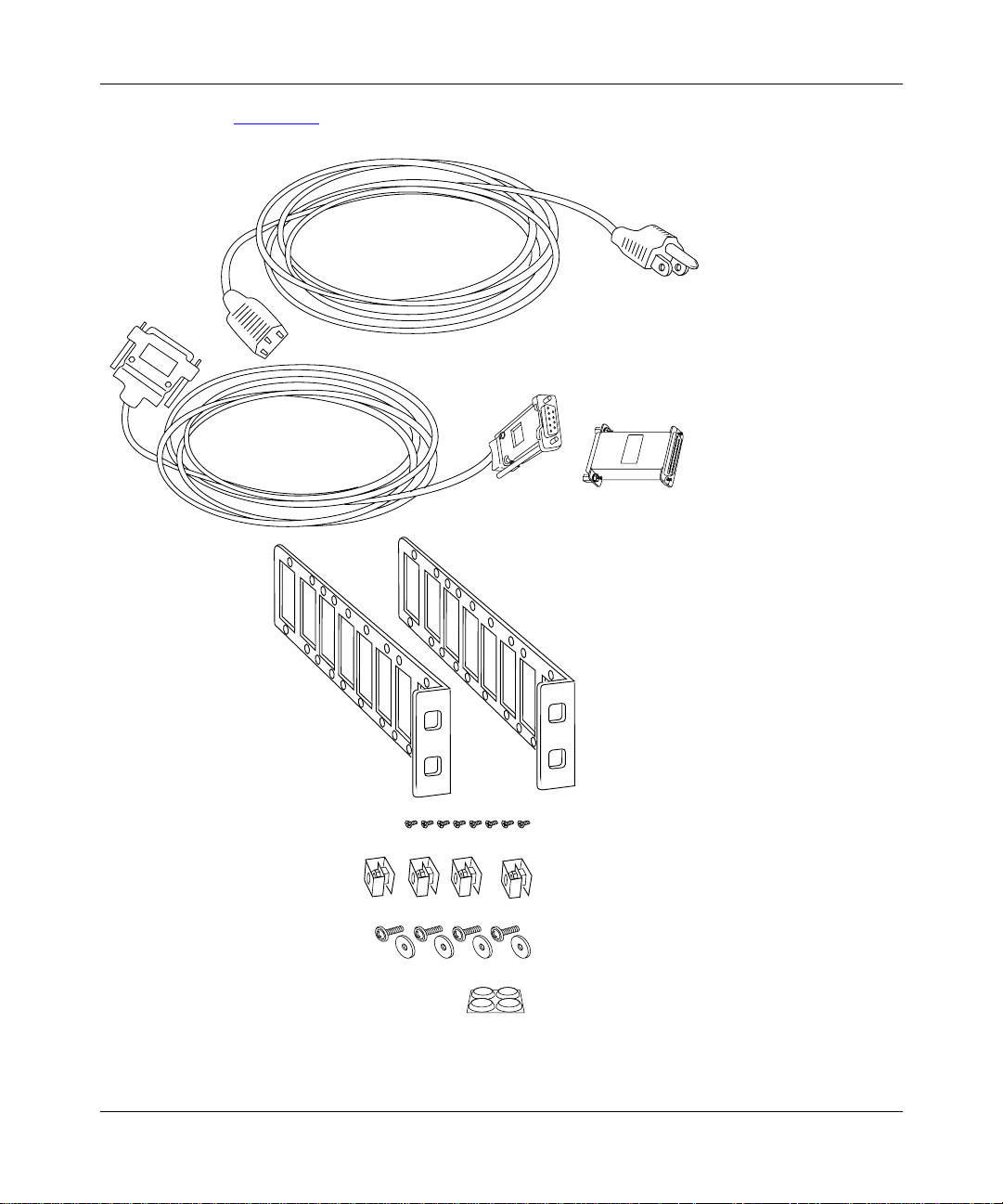
Installing the ARN
Figure 1-1 illustrates the ARN hardware accessory items.
Power Cable
Console/Modem Cable
(DB-9 Receptacle
to DB-25 Plug Cable)
DB-25 Receptacle
Null Modem Adapter
Two Flange Brackets
Eight #6 Phillips Screws
Four Cage Nuts
Four #10 Cagenut Screws and Washers
Four Rubber Feet
Figure 1-1. Accessories in the ARN Shipping Container
114200-D Rev 00
ARN0048B
1-3
Page 26

Installing and Operating BayStack ARN Routers
Additional Equipment
To install the ARN, you may need some additional items that are not part of the
ARN accessory package. Before installing the ARN hardware, ensure that you
obtain all the cables, tools, and other equipment that you need.
Cables
Unless they were specifically ordered, the cables necessary for your network
configuration are not part of the ARN accessory package. If you do not have the
proper cables, contact your network administrator or see the Cable Guide.
Management Console
You can attach an optional computer terminal or PC as a console to the ARN to
monitor the re sults o f star tup diag nosti cs and p erform manual b oot conf igu ratio ns.
Or you can attach any AT-compatible modem to allow remote dial-in access to
diagnostics and configuration.
Note:
T o use the Netboot, Directed Netboot, or Local Boot option s for booting
and configuring the ARN (see Chapter 3, “Operating the ARN”), you must
have a local terminal connected the first time the ARN powers up.
1-4
Mounting Hardware
To rack-mount the ARN, you need a Phillips screwdriver and an electronic
enclosure rack that meets the following specifications:
• Heavy-duty steel construction
• Electronic Industries Association (EIA) standard hole-spacing
• Width of 19 in. (48.26 cm) and depth of 24 in. (60.96 cm)
If the rack does not have threaded rail holes, you must use cage nuts (see
Figure 1-1
) to use with the cagenut screws.
114200-D Rev 00
Page 27

Verifying Site Requirements
The installation site must provide a certain amount of free space around the ARN
to dissipate heat, as de tailed in Table 1-1
Table 1-1. Installation Space Requirements
Width Depth (minimum) Depth (for servicing)
22.5 in. (57.2 cm) 15 in. (38.1 cm) 25 in. (63.5 cm)
In addition, the installation site must meet the electri cal and environmental
specifications listed in Appendix C.
Installing the ARN
.
Caution:
You must use grounded electrical power outlets with the ARN.
Installing the ARN
Once you are ready to install the ARN in its final location, you have two options:
• Position the ARN on a flat, sturdy, horizontal surface.
• Mount the ARN in an electronic enclosure rack.
Positioning the ARN on a Flat Surface
When positioning the ARN on a flat surface, make sure that the surface is:
• Large enough for the ARN to operate properly (Table 1-1)
• Sturdy enough to support the combined weight of the ARN and any cables
that you connect
You should place the self-adhesive, rubber feet (shipped with the AR N) on the
bottom of the ARN chassis. These feet not only protect the surface on which you
position the ARN, they provide added friction against the weight of any cables
that you attach to the device.
114200-D Rev 00
1-5
Page 28

Installing and Operating BayStack ARN Routers
Rack-Mounting the ARN
For this procedure, you need:
• Two flange brackets and eight #6 Phillips screws (shipped with the ARN)
• A Phillips screwdriver
• An electronic enclosure rack . If the rack does no t hav e threade d rail holes, you
must attach the four cage nuts shipped with the ARN.
• Four #10 cagenut screws and washers (shipped with the ARN)
To rack-mount the ARN:
1.
Determine how you want the ARN to fit in the equipment rack.
Multiple holes in the flange brackets provide several options for
rack-mounting the ARN. How you attach the flange brackets determines how
far the router extends outside or remains inside the rack. Figure 1-2
three of the most common locations for the brackets.
2.
Attach a flange bracket to each side of the ARN.
a.
Align four bracket holes with four holes in the ARN enclosure
(Figure 1-2)
.
shows
1-6
b.
Insert a #6 Phillips screw through each hole and into the ARN.
c.
Tighten the four screws with a Phillips screwdriver.
114200-D Rev 00
Page 29

Installing the ARN
B1
Screws
(4 places)
B2
DD
ISDN BRI
withNT1
1
2
RLSD
Screws
1
2
(4 places)
Front panel
1
2
DD
ISDN BRI
withNT1
RLSD
Front panel
Figure 1-2. Options for Attaching Flange Brackets to Rack-Mount the ARN
3.
If the holes in the rack’s vertical supports are not threaded for cagenut
screws, insert a cage nut in four locations (Figure 1-3)
.
B1
B2
ARN0004B
114200-D Rev 00
1-7
Page 30

Installing and Operating BayStack ARN Routers
U
D
1
2
B1
ISDN BRI
DD
B2
withNT1
COM
RLSD
Serial
10BaseT
Tx
AUI
Rx
Cl
Ethernet 2
10BaseT
Tx
AUI
Rx
Cl
Ethernet 1
Cagenut Screw
(4 Places)
Rail without
Threaded Holes
RLSD3
COM3 COM4 COM5
RLSD4
RLSD5
Run
Pwr
Base
Expansion
Boot
RPS
Adapter1
DCM
Fail
Fan
Adapter2
PCMCIA
Serial
BayStack Advanced Remote Node
1-8
Use Cage Nut
ARN0005A
Figure 1-3. Installing the ARN in an Electronic Enclosure Rack
4.
Insert a cagenut screw through each bracket hole and into the
corresponding holes in the rack.
5.
Tighten each cagenut screw with a Phillips screwdriver.
114200-D Rev 00
Page 31

A
Understanding the ARN Module Locations
The ARN is designed to scale to your needs. In addition to either an Ethernet or
token ring base mod ule, t he ARN can con tain an opt ional LAN e xpansi on module
and up to two WAN adapter modules (Figure 1-4
).
Installing the ARN
Adapter modules
U
D
1
2
ISDN BRI
withNT1
RLSD
B1
DD
B2
COM
Serial
10BaseT
Tx
Rx
Cl
Ethernet 1
Figure 1-4. ARN Module Locations
The ARN is available in the following base module configurations:
• One Ethernet AUI and Ethernet 10BASE-T interface
• One Ethernet 10/100BASE-Tx interface
• One Ethernet 100BASE-Fx interface
• One Token Ring interface (STP only)
ARN expansion modul es provi de additional E thernet (AUI and 10B ASE-T), toke n
ring (STP and UTP), and serial interfaces. Each ARN WAN adapter module adds
one serial, ISDN BRI, V.34 modem, T1/FT1, E1/ET1, 56/64K DSU/CSU, or X.25
PAD interface.
Expansion module
RLSD3
RLSD4
RLSD5
AUI
Run
Boot
Fail
COM3 COM4 COM5
Serial
Pwr
Base
Expansion
RPS
Adapter1
DCM
Fan
Adapter2
PCMCIA
Base module
BayStack Advanced Remote Node
ARN0006
114200-D Rev 00
The Ethernet base and expansion modules can also contain an optional data
collection module (DCM). This optional DCM gathers Ethernet statistics for a
remote monitoring (RMON) utility. A subset of these statistics is gathered with a
built-in RM ON function on the Ethernet10/100BASE-Tx and -Fx interfaces. See
Configuring RMON and RMON2 on BayRS Routers for information about h ow to
enable and use each RMON data collection implementation.
1-9
Page 32

Installing and Operating BayStack ARN Routers
Connecting Communications Cables
Gather the communications equipment and cabling that you will attach to the
ARN. If you do not have the proper cables, contact your netw or k admi nis tr at or or
see the Cable Guide.
Note:
For cable interface descriptions, see Appendix C.
Then, complete the steps in the applicable sections:
• “Connecting to an Ethernet Interface” on page 1-10
• “Connecting to a Token Ring Interface” on page 1-14
• “Connecting to a Serial Interface ” on page 1-16
• “Connecting to the ISDN Interface” on page 1-18
• “Connecting to the 56/64K DSU/CSU Interface” on page 1-19
• “Connecting to the FT1/T1 DSU/ CSU Interface” on page 1-20
• “Connecting to the E1/FE1 DSU/ CSU Interface” on page 1-21
• “Connecting to the X.25 PAD Interface” on page 1-24
Connecting to an Ethernet Interface
You can connect an Ethernet cable to any ARN base or expansion module that
contains an Ethernet interface option.
Note:
On Ethernet modules that offer two interface types -- an attachment unit
interface (AUI) transceiv er interf ace or a UTP inter face -- you can onl y use one
interface at a ti me . F or example, you can connect to either t he AUI transceiver
interface or the 10BASE-T UTP interface on the base module, but you cannot
use both interfaces at the same time.
1-10
114200-D Rev 00
Page 33

Installing the ARN
Connecting to the AUI
The AUI interface provides broadband, baseband, fiber, and shielded twisted pair
(STP) support, depending on the transceiver and cables you use.
Caution:
Connecting the ARN AUI interface directly to the AUI interface on
an Ethernet station violates IEEE 802.3 standards. The AUI interface is
designed only for connection to a transceiver.
To attach an Ethernet AUI transceiver (drop) cable to the AUI connector on an
Ethernet module:
1.
Connect an Ethernet AUI drop cable to the interface labeled AUI
(Figure 1-5
).
The cable must have a 15-position D-SUB receptacle.
Expansion module AUI interface
Base module AUI interface
U
D
1
2
ISDN BRI
withNT1
RLSD
B1
DD
B2
COM
Serial
10BaseT
Tx
Rx
Cl
10BaseT
Tx
Rx
Cl
AUI
Ethernet 2
AUI
Ethernet 1
RLSD3
RLSD4
RLSD5
Run
Boot
Diag
COM3 COM4 COM5
Serial
Pwr
Base
Expansion
RPS
Adapter1
DCM
Fan
Adapter2
PCMCIA
BayStack Advanced Remote Node
Ethernet AUI drop cable
To
Ethernet
transceiver
Figure 1-5. Connecting an AUI Cable
2.
Secure the AUI cable using the slide lock on the interface.
3.
Connect the other end of the cable to an Ethernet transceiver.
114200-D Rev 00
ARN0063A
1-11
Page 34

Installing and Operating BayStack ARN Routers
B
Connecting to the UTP Interface
To connect an unshielded twisted-pair (UTP) cable to the base module or
expansion module Ethernet interface, insert the UTP jack into the RJ-45
receptacle connector, as shown in Figure 1-6
Expansion module 10BASE-T interface
Base module 10BASE-T interface
and Figure 1-7.
U
D
1
2
ISDN BRI
withNT1
RLSD
B1
DD
B2
COM
Serial
To
Ethernet
network
10BaseT
Tx
Rx
Cl
10BaseT
Tx
Rx
Cl
AUI
Ethernet 2
AUI
Ethernet 1
RLSD3
RLSD4
RLSD5
Run
Pwr
Base
Boot
RPS
Adapter1
Diag
Fan
Adapter2
Ethernet 10BASE-T cables
Figure 1-6. Connecting an Ethernet 10BASE-T Cable
Expansion module 10BASE-T interface
Base module 10/100 BASE-Tx interface
U
D
1
2
ISDN BRI
withNT1
RLSD
B1
DD
B2
COM
Serial
10BaseT
Tx
Rx
Cl
10/100 BaseTx
Tx
Rx
Cl
Ethernet 2
AUI
RLSD3
RLSD4
RLSD5
Run
Pwr
Base
Boot
RPS
Adapter1
Diag
Fan
Adapter2
COM3 COM4 COM5
Serial
Expansion
DCM
PCMCIA
COM3 COM4 COM5
Expansion
DCM
PCMCIA
BayStack Advanced Remote Node
Serial
BayStack Advanced Remote Node
ARN0062A
To
Ethernet
network
Ethernet 10/100 BASE-Tx cables
Figure 1-7. Connecting an Ethernet 10/100BASE-Tx Cable
1-12
ARN0062
114200-D Rev 00
Page 35

Installing the ARN
Connecting to the Fiber Interface
To connect a fiber cable to the base module or expansion module Ethernet
interface, ins ert the fiber cable jack into the i nterface as shown in Figure 1-8
Expansion module 10BASE-T interface
Base module 100BASE-FX interface
.
U
D
1
2
ISDN BRI
withNT1
RLSD
B1
DD
B2
COM
Serial
Link
100
10BaseT
Tx
Rx
Cl
Tx
Rx
AUI
Ethernet 2
100 BaseFX
Ethernet 1
RLSD3
RLSD4
RLSD5
Run
Boot
Diag
COM3 COM4 COM5
Pwr
Base
Expansion
RPS
Adapter1
DCM
Fan
Adapter2
PCMCIA
Ethernet 100BASE-FX cables
To
Ethernet
network
Figure 1-8. Connecting an Ethernet 100BASE-Fx Cable
Serial
BayStack Advanced Remote Node
ARN0062C
114200-D Rev 00
1-13
Page 36

Installing and Operating BayStack ARN Routers
A
Connecting to a Token Ring Interface
You can connect a token ring cable to any ARN base module or e xpansi on module
that contains a token rin g interface option. Each o f these inte rface options offers
two token ring interface types: an STP interface or a UTP interface.
Note:
You can use only one token ring int erf ace o n an ARN bas e or ex pansio n
module at any time. For example, you can connect to either the STP interface
or the UTP interface on a base module, but you cannot use both interfaces at
the same time.
Connecting to the STP Interface
To connect a token ring shielded twisted pair (STP) cable to the base module or
expansion module token ring interface:
1.
Attach the 9-pin D-SUB plug to the toke n ring STP inte rface (Figur e1-9).
Expansion module STP interface
Base module STP interface
U
D
1
2
ISDN BRI
withNT1
RLSD
B1
DD
B2
COM
Serial
STP
Token Ring 2
STP
Token Ring 1
UTP
RCVR
NSRT
WFLT
RCVR
NSRT
WFLT
RLSD3
RLSD4
RLSD5
Run
Boot
Fail
COM3 COM4 COM5
Serial
Pwr
Base
Expansion
RPS
Adapter1
DCM
Fan
Adapter2
PCMCIA
BayStack Advanced Remote Node
To
Token Ring
network
Token Ring STP cable
Figure 1-9. Connecting a Token Ring STP Cable
2.
Secure the token ring cable using the capture screws.
1-14
ARN0068
114200-D Rev 00
Page 37

Installing the ARN
Connecting to the UTP Interface
To connect a token ring UTP cable to the expansion module token ring interface,
insert the RJ-45 connector into the UTP interface, as shown in Figure 1-10
Expansion module UTP interface
.
U
D
1
2
ISDN BRI
withNT1
RLSD
B1
DD
B2
COM
Serial
STP
Token Ring 2
STP
Token Ring 1
UTP
RCVR
NSRT
WFLT
RCVR
NSRT
WFLT
To
Token Ring
network
RLSD3
RLSD4
RLSD5
Run
Boot
Fail
Token Ring UTP cables
Figure 1-10. Connecting a Token Ring UTP Cable
COM3 COM4 COM5
Serial
Pwr
Base
Expansion
RPS
Adapter1
DCM
Fan
Adapter2
PCMCIA
BayStack Advanced Remote Node
ARN0069A
114200-D Rev 00
1-15
Page 38

Installing and Operating BayStack ARN Routers
Connecting to a Serial Interface
You connect 44-pin serial cables t o the connec tors on ARN ad apter and e xp ans ion
modules. Each serial inte rf ace suppo rts mult iple WAN protocols at a transmission
rate of 1200 b/s to 2.048 Mb/s.
To connect to the serial interface:
1.
Locate the serial interface cable.
The serial interfaces automatically configure the desired electrical interface
when used with sta ndard k e yed cab les. For information about cabl es a vailable
from Bay Networks, see the Cable Guide.
Note:
The Cable Guide refers to serial cables that transmit synchronous data
as “synchronous” cables.
2.
Connect the cable to an expansion module serial interface (Figure 1-11)
or an adapter module serial interface (Figure 1-12)
.
U
D
1
2
ISDN BRI
withNT1
RLSD
B1
DD
B2
COM
Serial
10BaseT
Tx
Rx
Cl
10BaseT
Tx
Rx
Cl
AUI
Ethernet 2
AUI
Ethernet 1
RLSD3
RLSD4
RLSD5
Run
Boot
Fail
To
RS-232,
RS-422,
RS-530,
V.28,
V.35,
or X.21
interface
COM3 COM4 COM5
Pwr
Base
Expansion
RPS
Adapter1
DCM
Fan
Adapter2
PCMCIA
Figure 1-11. Connecting Serial Cables to an Expansion Module
Connector numbering on expansion module serial interfaces begin with
COM3.
1-16
Serial
BayStack Advanced Remote Node
ARN0067A
114200-D Rev 00
Page 39

1
2
Tx
Rx
Cl
Tx
Rx
Cl
10BaseT
Ethernet 1
10BaseT
Ethernet 2
Installing the ARN
U
ISDN BRI
RLSD
withNT1
D
B1
DD
B2
COM
To
RS-232,
RS-422,
RS-530,
V.28,
V.35,
or X.21
interface
ARN0066A
Figure 1-12. Connecting a Serial Cable to the Serial Adapter Module
Serial adapter modules, labeled COM, can be in position 1 or 2. These
interfaces are COM1 and COM2.
3.
Secure the cable to the interface using the capture screws on the cable.
4.
Connect the remote end of each cab le to the appr opriate communicati ons
equipment.
114200-D Rev 00
1-17
Page 40

Installing and Operating BayStack ARN Routers
1
2
Tx
Rx
Cl
Tx
Rx
Cl
10BaseT
Ethernet 1
10BaseT
Ethernet 2
Connecting to the ISDN Interface
You connect ISDN service to the connector on an installed ISDN BRI U or ISDN
BRI S/T adapter module. Modules with an S/T interface provide dialup
connection to the ISDN network through a terminal adapter. Modules with a U
interface allow you to connect directly to the ISDN network switch.
The BRI provides two B channels, and supports full D-channel signaling and
call setup/teardown as defined in 1988 CCITT (now ITU-T) Recommendation
Q.921 and Q.931. For more info rmation, refer to Configuring Dial Services.
To connect ISDN BRI services:
1.
Insert the ISDN cable i nto the I SDN BRI S /T or U int erface (Figur e 1-13).
RLSD
To
ISDN
Network
U
ISDN BRI
withNT1
D
B1
DD
B2
COM
Serial
ARN0064A
Figure 1-13. Connecting the ISDN BRI Cable
2.
Connect the other end of the cable to the ISDN communications device.
1-18
114200-D Rev 00
Page 41

DDS
TxD
RxD CDTest
1
2
56K/64K
DSU/CSU
Tx
Rx
Cl
Tx
Rx
Cl
10BaseT
Ethernet 1
10BaseT
Ethernet 2
Connecting to the 56/64K DSU/CSU Interface
You connect 56/64K DSU/CSU service to the connector on an installed 56/64K
DSU/CSU adapter module.
To connect to the 56/64K DSU/CSU interface:
1.
Insert the 56/64 K DSU/CSU cable connector into the DSU/CSU interface
labeled DDS (Figure 1-14
S/T
ISDN BRI
To
Digital line
wall jack
).
Installing the ARN
ARN0065A
Figure 1-14. Connecting the 56/64K DSU/CSU Cable
2.
Connect the other end of the cable to a digital line (for example, a digital
line wall jack that connects to an office channel unit [OCU]).
114200-D Rev 00
1-19
Page 42

Installing and Operating BayStack ARN Routers
1
2
Tx
Rx
Cl
Tx
Rx
Cl
10BaseT
Ethernet 1
10BaseT
Ethernet 2
Connecting to the FT1/T1 DSU/CSU Interface
You connect FT1/T1 DSU/CSU service to the connector on an installed FT1/T1
DSU/CSU adapter module.
To connect to the FT1/T1 DSU/CSU interface:
1.
Insert the RJ-48C cable connector into the FT1/T1 DSU/CSU interface
on the adapter module (Figure 1-15
S/T
ISDN BRI
Compiles with FCC Rules Part 68
Reg. Number 4P8USA-31445-DE-N
FT1/T1
DSU/CSU
Red Alm
Yel Alm
Loop
Sync
).
To
T1device
ARN0065B
Figure 1-15. Connecting the FT1/T1 DSU/CSU Cable
2.
Connect the other end of the cable to a T1 communications device.
1-20
114200-D Rev 00
Page 43

Connecting to the E1/FE1 DSU/CSU Interface
You connect E1/FE1 service to the connector on an installed E1/FE1 adapter
module.
To connect to the E1/FE1 interface:
1.
Insert the RJ-48C cable connector into the E1/FE1 interface
(Figure 1-16
).
Installing the ARN
1
2
E1/FE1
G.703
Local Alarm
Remote Alarm
Loop
Sync
ARN0090B
Figure 1-16. Connecting the E1/FE1 Cable
2.
Connect the other end of the cable to a FE1communications device.
114200-D Rev 00
1-21
Page 44

Installing and Operating BayStack ARN Routers
1
2
Tx
Rx
Cl
Tx
Rx
Cl
10BaseT
Ethernet 1
10BaseT
Ethernet 2
Connecting to the Integrated V.34 Modem
You connect dial services to the connector on an installed V.34 Modem adapter
module.
To connect a telephone cable to the integrated V.34 modem:
1.
Connect the RJ-11 telephone cable to the V.34 modem interface
(Table 1-17)
RLSD
.
Front-panel V.34 Modem Interface
COM
Telco
V.34 Modem
To
RJ-11 telephone
receptacle
Serial
Tx
RLSD
Rx
DTR
ARN0071A
Figure 1-17. Connecting a Telephone Cable
2.
Connect the other end of the cable to an analog telephone line.
Table 1-2
Note:
provides the default settings for the V.34 Modem adapter module.
The default settings for the front-panel V.34 Modem adapter module
differ from the default settings for the back-panel V.34 Console Modem
module interface. For information about the back-panel V.34 Console Modem
and its default settings, see “Connecting a Console Modem” on page 1-29
1-22
114200-D Rev 00
.
Page 45

Installing the ARN
Table 1-2. V.34 Front-Panel Modem Adapter Module Defaults
Modem Signal/Pa rame ter Default Value
Clear To Send (CTS) On
Data Terminal Ready (DTR) Depends on the modem type. Set the modem to
answer incoming calls when DTR is active.
Data Carrier Detect (DCD) or
received lin e sign al detect ion
(RLSD)
Data Set Ready (DSR) On
Ready to Send (RTS) Ignore
Synchronous/Asynchronous Mode Asynchronous
AutoAnswer Set on
Local Character Echo Off
Supervisory Functions Off
Baud Rate 28800
Data Bits 8
Stop Bits 1
Parity None
On while carrier is present (the ARN uses DCD to
detect modem connect and disconnect).
rings with DTR active (n must be greater
n
than 0).
114200-D Rev 00
1-23
Page 46

Installing and Operating BayStack ARN Routers
Connecting to the X.25 PAD Interface
To support X.25 PAD applications, the ARN router requires the following
hardware:
• ARN X.25 PAD adapter module
• Breakout box
To connect X.25 PAD services:
1.
Position the X.25 breakout box above the ARN in one of the following
ways:
• Attac h the rubber feet that came in the shipping container to the four
raised areas on the bottom of t he break out box ch assis; t hen, place t he box
on top of the ARN (Figure 1-18
• Using the screw holes on the sides of the breakout box, install the box
above the ARN in a standard equipment rack. For information about
rack-mounting the ARN, see “Rack-Mounting the ARN” on page 1-6
2.
Connect the DB-60 cable on the breakout box to the X.25 PAD connector
on the installed module (Figure 1-18
).
.
).
DB-60 cable
1
2
RLSD
X.25 PAD
10BaseT
TX
RX
COM
Serial
Tx
Rx
Cl
10BaseT
Tx
Rx
Cl
DB-25 connector ports
AUI
Ethernet 2
AUI
Ethernet 1
RLSD3
COM3 COM4 COM5
RLSD4
RLSD5
Run
Pwr
Base
Expansion
Boot
RPS
Adapter1
DCM
Fail
Fan
Adapter2
PCMCIA
Serial
Figure 1-18. Connecting a Breakout Box to the X.25 PAD Interface
3.
Connect the appropriate WAN cabling to each of the eight DB-25
interfaces on the breakout box that you will use.
For information on cables available from Bay Networks, see the Cable Guide.
1-24
BayStack Advanced Remote Node
ARN0088A
114200-D Rev 00
Page 47

Connecting a Management Co nsole
You can use the back-panel console ports to connect one or both of the following
management devices:
• PC or terminal
• External modem or telephone connection to optional integrated V.34 modem
Using a local console, you can moni to r the results of the ARN startup diagnostics
and set the boot configuration. Using an attached modem, you can enable remote
dial-in access for various management tasks.
Note:
To use the Netboot, Directed Netboot, or Local Boot software
configuration options described in Chapter 2, “Starting the ARN,” you must
connect a management console the first time you power up the ARN.
Connecting a PC Console
To connect a PC to the ARN, you need a standard AT serial cable with a 25-pin
plug connector, plus these pieces from the ARN console/modem cable kit:
Installing the ARN
114200-D Rev 00
• Serial console/modem cable with 9-pin receptacle to 25-pin plug connectors
(Order No. 110307)
• Null modem crossover adapter with two 25-pin receptacle connectors
(Order No. 110308)
Once you have the correct equipment, complete the following steps:
1.
Configure the PC console, using the following parameters and
instructions in your PC documentation.
• Baud rate 9600
• 8 data bits
•1 stop bit
• No parity
2.
Turn off the PC.
3.
Insert the 9-pin receptacle end of the console cab le int o t he ARN Console
interface (Figure1-21)
.
1-25
Page 48

Installing and Operating BayStack ARN Routers
Console Modem
Console/modem cable
Figure 1-19. Connecting the Console/Modem Cable
4.
Attach the null modem crossover adapter to the other end of the console
cable (Figure 1-20)
.
ARN0083B
1-26
Console cable connector
Rotate to tighten screw
Null modem crossover adapter
Screw receptacle
AN0010A
Figure 1-20. Attaching the Null Modem Crossover Adapter
5.
Connect the other end of the null modem crossover adapter to the 25-pin
plug connector on a standard AT serial cable.
6.
Connect the complete cabl e unit to the communications interface at the
back of the PC (Figure 1-21)
.
114200-D Rev 00
Page 49

Installing the ARN
U
L
100-240~
1.2A
50-60Hz
Redundant Power
U
L
Modem
PC cable
Null modem adapter
Console cable
Figure 1-21. Connecting a PC Console to an ARN
Connecting a Terminal Console
To connect a terminal console to the ARN, you need both of these pieces in the
ARN console/modem cable kit (Order No. 110310):
• Serial console/modem cable with 9-pin receptacle to 25-pin plug connectors
(Order No. 110307)
• Null modem crossover adapter with two 25-pin receptacle connectors
(Order No. 110308)
Once you have the appropriate equipment, complete the following steps:
114200-D Rev 00
ARN0056A
1-27
Page 50

Installing and Operating BayStack ARN Routers
1.
Turn on and configure the terminal, using the parameters in Table 1-3
and the terminal user guide.
Table 1-3. Console Parameters
Parameter Value
Baud Rate 9600
Data Bits 8
Stop Bits 1
Parity None
2.
Turn off the te rminal.
3.
Insert the 9-pin receptacle end of the console cab le int o t he ARN Console
connector.
4.
Attach the null modem crossover adapter to the 25-pin connector.
Insert the screw on the cable connector into the receptacle on the adapter
connector and tighten the screw (refer to Figure 1-20
on page 1-26).
1-28
5.
Attach the 25-pin receptacle connector on the combined cable and
adapter to the console host connector (Figure 1-22)
U
L
100-240~
1.2A
50-60Hz
Redundant Power
U
L
Console Modem
.
COMM
20 mA PR
KB
Console cable plus
null modem adapter
Figure 1-22. Connecting a Terminal Console to an ARN
ARN0058A
114200-D Rev 00
Page 51

Connecting a Console Modem
A modem provides a system administrator with remote access to the ARN. It is a
good idea to connect a modem in case the ARN experiences system problems.
Note:
To use the Netboot, Directed Netboot, or Local Boot software
configuration options, you must connect a console the first time you power up
the ARN. Refer to Chapter 2, “Starting the ARN,” for details.
To use a modem connection for a management console, you can connect an
external modem to the modem interface or you can connect a telephone line
directly to an optional V.34 Console Modem adapter module. Both ports are on
the ARN back panel.
Installing the ARN
Table 1-4
provides the default settings for both types of back-panel modem
interfaces.
Table 1-4. Console Modem Defaults
Modem Signal/Pa rame ter Default Value
Clear To Send (CTS) On
Data Terminal Ready (DTR) Set to answer all incoming calls.
Data Carrier Detect (DCD) or
Received Line Signal Detection
(RLSD)
Data Set Ready (DSR) On
Ready to Send (RTS) Ignored
Synchronous/Asynchronous Mode Asynchronous
AutoAnswer Answer on 2 ri ngs with DTR active.
Local Character Echo Off
Supervisory Functions Off
Baud Rate 9600
Data Bits 8
Stop Bits 1
Parity None
On while carrier is present (the ARN uses DCD to
detect modem connect and disconnect).
114200-D Rev 00
1-29
Page 52

Installing and Operating BayStack ARN Routers
A
Connecting an External Console Modem
To connect an external modem to the ARN back panel, you need an AT or Hayes
compatible modem and the modem cable (Order No. 110307) that came in the
ARN console/modem cable kit.
Do not use the n ull mod em cros so v er a dapter (Orde r No. 110308) in t he
Note:
ARN cable kit to connect to a modem.
Complete the fo llowing steps:
1.
Configure the modem, using the parameters in Table 1-4.
Refer to the mo dem user guid e for instructions.
2.
Turn off the modem.
3.
Insert the 9-pin rece pta cle end of the modem ca ble into t he ARN Console
interface (Figure 1-23)
4.
Insert the 25-pin plug at the other end of the modem cable into the
.
modem RS-232 data communications interface
.
1-30
U
L
100-240~
1.2A
50-60Hz
Redundant Power
U
L
Console
Modem cable
Figure 1-23. Connecting an External Console Modem
PHONE
DIAL
NMS DTE
(LEASE
(LEASED)
DWR
3810
3810
ARN0057
114200-D Rev 00
Page 53

Installing the ARN
Connecting to an Integrated V.34 Console Modem Module
If your ARN contains an opti onal V.34 Console Modem module , you ca n connect
the RJ-11 jack from the telephone line directly to the V.34 Console Modem
interface. Table 1-4
on page 1-29 provides the default parameter settings for the
V.34 Console Modem.
Back-panel V.34 Modem Interface
TxRxRLSD
Modem
DTR
ARN0072A
To
RJ-11 telephone
receptacle
Console
Modem
Figure 1-24. Connecting to an Integrated Console Modem
114200-D Rev 00
1-31
Page 54

Installing and Operating BayStack ARN Routers
Connecting the Power Cable
Danger:
Be sure that the power switch on the ARN back panel is in the OFF
(0) position before you connect the power cable.
To connect the power cable to the ARN, complete these steps:
1.
Connect the power cable to the power connector on the left side of the
ARN back panel (Figure 1-25)
Power switch (off)
To power outlet
100-240~
1.2A
50-60Hz
.
U
L
Redundant Power
U
L
To redundant power supply
1-32
Figure 1-25. Connecting the Power Cable to the ARN
2.
Connect the rem ote end of the power cable to a grounded outlet.
Note:
For information about connecting a redundant power supply to the
ARN, refer to the documentation that came with your power supply.
114200-D Rev 00
Page 55

Installing the Flash Memory Card
Bay Networks ships the router software on a PCMCIA flash memory card
(Figure 1-26)
System (NVFS) in the ARN.
Figure 1 -26. Flash Memory Card
. The flash memory card provides storage for the Nonvolatile File
INSERT
A
A
Installing the ARN
Before starting the ARN, install the flash memory card supplied with the router:
1.
Position the card with the label facing up and the INSERT arrow
pointing toward the card receptacle.
2.
Insert the card into the receptacle (Figure 1-27) and gently push the ca rd
until it fits snugly into place.
U
L
Redundant Power
100-240~
1.2A
50-60Hz
Figure 1-27. Inserting the Flash Memory Card in the ARN Receptacle
114200-D Rev 00
U
L
Console Modem
ARN0018A
1-33
Page 56

Installing and Operating BayStack ARN Routers
Where to Go Next
Use the following table to determine where you want to go next.
For information about Go to
Starting the ARN Chapter 2
Operating the ARN Chapter 3
Configuring the ARN for Netboot and Directed
Netboot
Using Local Boot (the Quick-Start Procedure) Appendix B
Technical Specifications Appendix C
Appendix A
1-34
114200-D Rev 00
Page 57

Chapter 2
Starting the ARN
This chapter describes how to start the BayStack ARN router, as follows:
Topic Go to
Understanding the startup process 2-1
Starting the ARN for the first time 2-4
Using EZ-Install 2-5
Using Netboot, Directed Netboot, or Local Boot 2-6
Where to go next 2-16
Understanding the Startup Process
To operate, the ARN requires two files: a software image and a configuration file.
Each time you start the ARN, it completes a process to load these files.
•The software image contains a group of executable files that support the
protocols that the network requires. The ARN uses the software image called
arn.exe. The process of obtaining and using this image is called booting.
• To bridge and route traffic, the ARN also needs a configuration file that is
tailored to the network. A configuration file is a binary system file that
contains hardware and software configuration data. The default configuration
file is named config.
Bay Networks ships the executable and default configuration files on a PCMCIA
flash card, b ut the ARN can also obtain them over the network. Getting a file over
the network is called net work booting, or netbooting . Getting a fi le from the router
file system, stored in flash memory, is local booting.
114200-D Rev 00
2-1
Page 58

Installing and Operating BayStack ARN Routers
When you start the ARN for the fi rst time, it complet es an initial sta rtup proced ure
to boot and connect to the network using either a default configuration file or one
already customized and available on the network.
You use one of four boot options to compl ete the initial sof tware startup. Table 2-1
summarizes the four optio ns; the sect ions that fol lo w prov ide steps f or completi ng
each option.
Table 2-1. Summary of Initial Startup Options
Source for
Boot
Option
EZ-Install Local Network
Netboot*
Directed
Netboot†
Local Boot Local Local The ARN boots from a local software image and generic
Source for
Image file
Local
or
Network
Local
or
Network
Configuration
File Description and Requirements
The default option. The ARN boots from local flash
(serial interface
only)
Local
or
Network
Local
or
Network
memory, then obtains its configuration file from a remote
workstation that is configured as a Bootstrap Protocol
(BootP) server. The ARN saves the configuration to the
flash memory
This option requires a High-Level Data Link Control
(HDLC) or frame relay serial connection.
The ARN locates and obt ains
a remote workstation that is configured as a BootP server.
This option requires a communications connection over
an HDLC, frame relay, Ethernet, token ring, or DSU/CSU
interface, and a local console connection.
The ARN obtains
workstation that is configured as a Trivial File Transfer
Protocol (TFTP) server. You must specify the IP address
of the TFTP server and the complete path to the startup
files before booting.
This option requires a communications connection over
an HDLC, frame relay, Ethernet, token ring, or DSU/CSU
interface, and a local console connection.
startup configuration file. You create a customized
configuration file by running the Quick-Start script.
.
at least one
at least one
startup file from a remote
startup file from
This option requires a local console connection and an
installed Ba yRS flas h memory card. If you attempt to loca l
boot the ARN/DC without the flash memory card inserted,
the router does not operate.
* The ARN supports netboot over serial, Ethernet, token ring, and 56/64K DSU/CSU interfaces only.
† The ARN supports directed netboot over serial, Ethernet, token ring, and 56/64K DSU/CSU interfaces only.
2-2
114200-D Rev 00
Page 59

Starting the ARN
You may not be able to use all met hods descr ibed in this cha pter to boot o v er so me
interfaces on your router. For example, you cannot netboot over an FT1/T1
interface. In some cases, you may use one interface to boot your router and then
switch to a different interface (such as the FT1/T1 DSU/CSU) to establish your
initial IP network connection to the management workstation.
Table 2-2
lists supported boot options by interface type.
Table 2-2. Supported Boot Options by Interface
Interface Supported Not Supported
Ethernet EZ-Install, Netboot, Directed
Netboot, Local boot
Token Ring EZ-Install, Netboot, Directed
Netboot, Local boot
Serial (synchronous) EZ-Install, Netboot, Directed
Netboot, Local boot
56K/64K DSU/CSU EZ-Install, Netboot, Directed
Netboot, Local boot
ISDN S/T (leased line) EZ-Install, Local boot Netboot, Directed Netboot
FT1/T1 DSU/CSU EZ-Install, Local boot Netboot, Directed Netboot
FE1/E1 DSU/CSU EZ-Install, Local boot Netboot, Directed Netboot
ISDN U (switched line) None All
V.34 modem None All
114200-D Rev 00
2-3
Page 60

Installing and Operating BayStack ARN Routers
Starting the ARN for the First Time
The ARN factory def aul ts ar e set to find the image file a nd configuration file from
the following locations:
• Image file -- on the local PCMCIA flash memory card
• Configuration file -- over the network
These default settings work with the default EZ-Install procedure.
The first time you power on an ARN, the router steps through its diagnostic tests
and then attempts to boot over all of its serial (C OM) interfaces u sing EZ-Install.
Note:
Coordinate the initial startup of the ARN with your network
administrator. To determine which software configuration option is best for
your site and for instructions on setting up a boot server, the network
administrator can refer to Configuring BayStack Remote Access.
If your network administrator has configured the network for the EZ-Install
procedure, the router boots using its local image and obtains its configuration file
over the network. Your network administrator can then connect to the ARN and
manage it remotely. For more information, refer to the next section, “
EZ-Install.”
Using
2-4
If your network administrator does not configure the network for EZ-Install, the
ARN cannot obtain its configuration file from the network, and the EZ-Install
procedure fails . The ARN then attempts to boot locally wit h t he configuration file
that resides on its flash memory card. Refer to “
Using Netboot, Directed Netboot,
or Local Boot” for more information.
If both the EZ-Install and local boot attempts fail, the EZ-Install and local boot
processes repeat until one of the following occurs:
• The ARN boots successfully.
• You interrupt the boot process to enter the ARN monitor.
• You turn off the ARN.
The follow ing sections describe how to use each of the different boot options for
the ARN.
114200-D Rev 00
Page 61

Using EZ-Install
EZ-Install is the default installation option provided by Bay Networks. This
option requires th at your netw ork a dminist rator has set up th e netw or k so that you
can start the EZ-Install procedure. In addition, this option requires that you:
• Install a flash memory c ard.
For instructions, see “Installing the Flash Memory Card” on page 1-33.
• Conn ect at least one serial (C OM) interfac e to the network.
For instructions, see “Connecting Communications Cables” on page 1-10.
Note:
If your ARN does not have a COM interface, you must configure the
ARN using one of the other methods such as netboot or directed netboot over
an Ethernet or token ring interface. Or, you may local boot the ARN and run
the Quick-Start script. For more information, see “Using Netboot, Directed
Netboot, or Local Boot” on page 2-6
To use E Z-Install:
Starting the ARN
.
114200-D Rev 00
1.
Press the power switch on the ARN back panel to the ON position.
The ARN comes on and activates EZ-Install.
Note:
If you power on the ARN before the network administrator is ready,
restart the ARN by pressing the reset button on the rear panel. See Chapter 3,
“Operating the ARN” for more information on resetting the ARN.
2.
Ensure that the ARN boots correctly.
When the ARN boots, its LEDs fl ash in a particular order. For information on
checking the ARN front-panel LEDs to ensure that the installation was
successful, see “Understanding the ARN LEDs” on page 3-1.
2-5
Page 62

Installing and Operating BayStack ARN Routers
Using Netboot, Directed Netboot, or Local Boot
When you netboot or local boot t he ARN, you must use a command line interface
that accesses the router software. To use a command line interface, you can:
• Wait for the ARN to local boot (that is, wait for the router to fail EZ-Install
and then attempt to boot using its local configuration file). After the ARN
boots locally, you can log in to the Technician Interface and redefine the boot
process.
• Interrupt the boot process using a break sequence and log in to the ARN
monitor to redefine the boot process.
Using the netboot, directed netboot, or local boot options requires that you:
• Connect any necessary communications cables to access the network.
• Connect a management console.
• Connect the ARN power cable.
• Install a flash memory c ard.
See Chapter 1, “Installing the ARN” for instructions on how to complete these
tasks.
Interrupting the Boot Process
Interrupting the boot process automatically starts the ARN monitor. Using the
ARN monitor allows you to bypass the EZ-Install procedure.
Note:
Before you power on the ARN, make sure that you have installed the
router and connected the management console equipment you need (see
“Connecting a Management Console” on page 1-25).
To interrupt the boot process:
1.
Press the power switch on the ARN back panel to the On position.
As the router powers on, your console displays the ARN diagnostic tests.
After successfully completing these tests, the router begins the EZ-Install
procedure and attempts to boot over the network.
2-6
114200-D Rev 00
Page 63

2.
While the router is running the EZ-Install procedure, issue a break
sequence from the management console.
The ARN monitor login prompt appears.
Note:
Be sure to issue a break sequence before the boot process completes.
Break sequences can vary, depending on the console type. Some management
consoles have specific “Break” keys on their keyboards; other require a key
sequence to issue a bre ak (for ex ample,
Cntrl-C
for your management console, see the PC/terminal documentation.
Logging in to the Command Line Software
Regardless of the command line software used (ARN monitor or Technician
Interface) the procedures to log in are identical.
To log in to the command line:
1.
Type the following command (noting the use of an uppe rcase “M”) at the
login prompt and press the Return key:
~ #
or
). For the break se quence
Starting the ARN
114200-D Rev 00
Manager
The T echnic ian Interf ace or ARN monitor command line prompt appears. You
are now using a command line interface to the router.
2.
To use the netboot, dir ect ed netboot, or the local boot option, go to one of
the following sections that describes the procedure you want to use:
• “Continuing with Netboot” on page 2-8
• “Continuing with Directed Netboot” on page 2-10
• “Continuing with Local Boot (the Quick-Start Procedure)” on page 2-13
2-7
Page 64

Installing and Operating BayStack ARN Routers
Continuing with Netboot
Note:
Continuing with the netboot option requires that you have already
logged in to either the ARN monitor or Technician Interface command line
software. For instructions, see “Logging in to the Command Line Software” on
page 2-7
T o use th e netboot option , you must ha ve at leas t one serial, Ethern et, or token ri ng
interface connected to the network. Before you start the netboot procedure, ask
your network administrator to:
• Verify that the network is set up for the netboot procedure, as described in the
• Provide you with the parameter arguments to the interface configuration
.
Configuring BayStack Remote Access guide.
command
ifconfig
The
ifconfig
you will use in Step 4.
command configures the parameters necessary to load the
software im age file and configuration file from a remote server over the
network.
2-8
Note:
Keep a record of the complete
ifconfig
command, because you need it
for future reference.
You can use the ARN monitor, Technician Interface, or Site Manager to perform
netboot. However, this guide assumes that you are using either the ARN monitor
or the Technician Interface.
To use the netboot option:
1.
At the command line prompt, enter the
ifconfig
command provided to
you by your network administrator and press the Return key.
The following is a sample command:
ifconfig com1 9.0.0.2 255.0.0.0 9.0.0.3
For more information about the
ifconfig
command, see “Using the ifconfig
Command” on page A-2.
2.
Enter the following command and p ress the Return key to verify the
configuration you specified in Step 1:
getcfg
114200-D Rev 00
Page 65

Starting the ARN
The getcfg command shows the source location, either local or network, of
the boot image file and the network configuration file. It also shows the
interface configuration settings that you specified using the
ifconfig
command.
If
getcfg displays the correct information, continue to the next step.
Otherwise, reenter the correct
ifconfig
command. If you need assistance,
contact your network administrator.
3.
Enter the following command and press the Return key to boot the ARN:
boot
Your console displays messages indicating the progress of the netboot
procedure.
Note:
If the ARN cannot find a software image file o r a configuration file
using the netboot procedure, it attempts to local boot once. If both attempts
fail, the ARN continues to net boot and lo cal boot until it boots successfully. If
the ARN remains in this loop, follow the steps in “Interrupting the Boot
Process” on page 2-6
.
114200-D Rev 00
4.
Ensure that the ARN boots correctly and successfully connects to the
network.
When the ARN boots, its LEDs flash in a particular order. To ensure that the
installation was successful, see “Ensuring a Successful Installation” on
page 3-9.
Contact your network administrator to verify that the ARN is now connected
to the network. Y our network administrator can refer to Configuring BayStac k
Remote Access to troubleshoot any problems.
If you need additional assistance, contact your local Bay Networks Technical
Solutions Center.
Note:
After connecting the ARN to the network, you can replace the local
management console with a modem connection to enable remote dial-in
access.
2-9
Page 66

Installing and Operating BayStack ARN Routers
Continuing with Directed Netboot
Note:
Continuing with the netboot option requires that you have already
logged in to either the ARN monitor or Technician Interface command line
software. For instructions, see “Logging in to the Command Line Software” on
page 2-7
You must have at least one serial, 56/64K DSU/CSU, Ethernet, or token ring
interface connected to the network to use the directed netboot option. Before you
start the directed netboot procedure, ask your network administrator to:
• Verify that the network is set up so that you can start the directed netboot
• Provide you with the parameter arguments to the interface configuration
.
procedure.
command
ifconfig
The
ifconfig
you will use in Step 1.
command configures the parameters necessary to load the
software image file and the configuration file from a remote server over the
network.
2-10
• Provide you with the boot configuration commands (
bconfig
) to use in
Step 2.
bconfig
The
command lets you specify the location of a startup file. To use
directed netboot, the location must include the following information:
-- The source (e ither local or network) of the image file and the
configuration file
-- The address of the TFTP server
-- The full directory path description locating the files on the TFTP server
Note:
Keep a record of the complete commands; you need them for future
reference.
You can use the ARN monitor, Technician Interface, or Site Manager to perform
directed netboot. However, this guide assumes that you are using either the ARN
monitor or the Technician Interf ace. To manage the ARN from a remote site, refer
to Configuring Bay Stack Remote Access.
114200-D Rev 00
Page 67

Starting the ARN
To use the directed netboot feature:
1.
At the command line pr ompt, enter the
ifconfig
command pro vided to you
by your network administrator and press the Return key.
The following is a sample command:
ifconfig com1 9.0.0.2 255.0.0.0 9.0.0.3
For more information about the ifconfig command, see “Using the ifconfig
Command” on page A-2.
2.
Enter the
bconfig
commands provided by your network administrator
and press the Return key.
You must enter one
bconfig command to specify the location of the software
image, and another to specify the location of the configuration file.
The following are sample command s:
bconfig image network 192.32.5.8 /usr/arnstartup/arn.exe
bconfig config network 192.32.5.8 /usr/arnstartup/config
For more information about the bconfig command, see “Using the bconfig
Command” on page A-7.
3.
Type t he following command and press the Return key to verify the
configuration you specified in Step 3:
getcfg
114200-D Rev 00
The get configuration data command getcfg shows the location of the boot
image file and network configuration file, the interface configuration settings
that you spec ified using the
information and file paths that you specified using the
Verify the interface configuration, as shown in Figure 2-1
ifconfig command, as well as the TFTP server
bconfig commands.
.
2-11
Page 68

Installing and Operating BayStack ARN Routers
$ getcfg
Boot Options
boot image = network
boot config = network
host IP address = 192.32.5.8
image pathname =
"/usr/arnstartup/krnl_arn.exe"
config pathname =
"/usr/arnstartup/config"
Netboot Parameters:
MAU1...None
XCVR2..None
COM1...IP=9.0.0.2, Mask=255.0.0.0, Next Hop=9.0.0.3
COM2...EZ-Install (disabled)
COM3...EZ-Install (disabled)
COM4...EZ-Install (disabled)
COM5...EZ-Install (disabled)
ARN0080A
2-12
Figure 2-1. Verifying Directed Netboot Configuration
If getcfg displays the correct information, continue to Step 4. Otherwise,
correct and reenter the
ifconfig and bconfig commands. If you need
assistance, contact your network administrator.
4.
Type the following command and press the Return key to boot the ARN:
boot
Note:
If the ARN cannot find a software image file o r a configuration file
using the direc ted netbo ot pro cedure, i t attempt s to n etboot on ce. If t he netboot
procedure fails, th e ARN tries to local boot once. If all th ree boot attempts fail,
the ARN continues to try directed netboot, netboot, and local boot until it
boots succes sfully. If the ARN remains in t his loop, follow the steps in
“Interrupting the Boot Proc ess” on page 2-6
5.
Ensure that the ARN boots correctly.
.
114200-D Rev 00
Page 69

When the ARN boots, its LEDs flash in a particular order. To ensure that the
installation was successful, see “Ensuring a Successful Installation” on
page 3-9.
6.
Ensure that the ARN is successfully connected to your network.
T o v erify that the ARN is no w connected to th e network, conta ct your network
administrator. To troubleshoot any problems, your network administrator can
refer to Configuring BayStack Remote Access.
If you need additional assistance, contact your local Bay Networks Technical
Solutions Center.
Note:
After connecting the ARN to the network, you can replace the
management console connection with a modem connection to enable remote
dial-in access.
Continuing with Local Boot (the Quick-Start Procedure)
Note:
Continuing with the netboot option requires that you have already
logged in to either the ARN monitor or Technician Interface command line
software. For instructions, see “Logging in to the Command Line Software” on
page 2-7
.
Starting the ARN
114200-D Rev 00
You can use either the ARN monitor or the Technician Interface to configure the
ARN to local boot. However, you must use the Technician Interface to run the
Quick-Star t script.
Note:
Before starting t he local boot procedure , ask your netw ork admini strator
to assist you in completing the Quick-Start worksheets in Appendix B.
2-13
Page 70

Installing and Operating BayStack ARN Routers
To use the local boot feature:
1.
At the command line prompt, type the following command and press the
Return key to configure the ARN to use its local config file:
bconfig config local
Note:
Since the defaul t settin g for f inding th e softw are image is local; you do
not have to change this setting for the local boot option.
2.
Type t he following command and press the Return key to boot the ARN :
boot
Note:
If the ARN tries to local boot and cannot find a software image file or a
configuration file, it attempts to n etboot once. If both attempts fail, the ARN
continues to local boot and netboot until it boots successfully. If the ARN
remains in this loop, follow the steps in “Interrupting the Boot Process” on
page 2-6
3.
.
Ensure that the ARN boots correctly.
2-14
When the ARN boots, its LEDs flash in a particular order. To ensure that the
installation was successful, see “Ensuring a Successful Installation” on
page 3-9.
After the ARN boots using it s local soft ware image and configuration file, the
Technician Interface login prompt appears.
4.
Type the following command (noting the use of an uppe rcase “M”) at the
login prompt and press the Return key:
Manager
The Technician Interface prompt ($) appears.
Note:
To check the contents of the router local file system on the installed
flash memory card, type
dir and press the Return key. The arn.exe software
image, config file, and inst_arn.bat file should appear among the files listed.
114200-D Rev 00
Page 71

Starting the ARN
5.
Enter the following command and press the Return key to run the
Quick-Start script:
run inst_arn.bat
The Quick-Start script begins running.
6.
Using your completed Quick-Sta rt worksheet fr om Appe ndix B, enter the
appropriate network information as the prompts appear.
The ARN uses this information to configure interfaces to the network.
For sample Quick-Start screen output and for information on using
Quick-Start commands, see Appendix B.
7.
Choose whether you want to configure another module/port.
Entering
interface prompt. Entering
n stops the Quick-Start script and returns you to the Technician
y allows you to configure another module/port.
Once the install script completes, the ARN starts bridging and routing traffic.
8.
Ensure that the ARN is successfully connected to your network.
T o v erify that the ARN is no w connected to th e network, conta ct your network
administrator. To troubleshoot any problems, your network administrator can
refer to Configuring BayStack Remote Access.
If you need additional assistance, contact your local Bay Networks Technical
Solutions Center.
Note:
After connecting the ARN to the network, you can replace the
management console connection with a modem connection to enable remote
dial-in access.
114200-D Rev 00
2-15
Page 72

Installing and Operating BayStack ARN Routers
Where to Go Next
Use the following table to determine where you want to go next.
For information about Go to
Operating the ARN Chapter 3
Configuring the ARN for Netboot and Directed
Netboot
Using Local Boot (the Quick-Start Procedure) Appendix B
Technical Specifications Appendix C
Appendix A
2-16
114200-D Rev 00
Page 73

Chapter 3
Operating the ARN
This chapter describes how to operate the BayStack ARN router, as follows:
Topic Page
Understanding LED descriptions 3-1
Ensuring a successful installation 3-9
Powering on and off the ARN 3-11
Resetting the ARN 3-12
Removing a flash memory card 3-13
Protecting memory card files 3-14
Where to go next 3-15
Understanding the ARN LEDs
Light-emitting diodes (LEDs) on the ARN provide information about how the
ARN is operating. The following sections describe the ARN LEDs:
• Base Module LEDs
• Expansion Module LEDs
• Adapter Module LEDs
Note:
For information about LEDs on the optional V.34 Modem Console
module on the ARN back panel, see Table 3-14
114200-D Rev 00
on page 3-9.
3-1
Page 74

Installing and Operating BayStack ARN Routers
Base Module LEDs
The base module includes diagnostic LEDs and LAN interface LEDs, visible on
the front panel of the ARN.
Diagnostic LEDs
The base module diagnostic LEDs (Figure 3-1
itself. All of these LEDs light briefly when you turn on the ARN power switch.
Run
Pwr
Base
Boot
RPS
Adapter1
Fail
Fan
Adapter2
U
D
1
2
ISDN BRI
withNT1
RLSD
B1
DD
B2
COM
Serial
10BaseT
Tx
Rx
Cl
10BaseT
Tx
Rx
Cl
AUI
Ethernet 2
AUI
Ethernet 1
RLSD3
RLSD4
RLSD5
Run
Boot
Diag
Figure 3-1. ARN Base Module Diagnostic LEDs
Table 3-1 describes the base module diagnostic LEDs.
) indicate the status of the ARN
Expansion
DCM
PCMCIA
COM3 COM4 COM5
Serial
Pwr
Base
Expansion
RPS
Adapter1
DCM
Fan
Adapter2
PCMCIA
BayStack Advanced Remote Node
ARN0059A
3-2
Table 3-1. Base Module Diagnostic LEDs
LED Meaning
Run Flashes for 1 to 3 minutes, indicating that diagnostic tests are running.
When it lights again and remains on, the ARN is operational.
Boot Lights for 1 to 3 minutes, indicating that diagnostic tests were
successful and the ARN is booting.
Fai l Lights again and remains on when diagnostic failure occurs.
(continued)
114200-D Rev 00
Page 75

Operating the ARN
Table 3-1. Base Module Diagnostic LEDs
LED Meaning
Pwr Lights and remains on when the ARN is on and receiving power.
RPS Lights and remains on when the redundant power supply (optional) is
operating.
Fan Lights and remains on if one or more ARN cooling fans stop operating.
Base Lights and remains on when the base module is operating properly.
Flashes slowly to indicate that the module is running its diagnostic
tests. Flashes rapidly to indicate that the module failed its diagnostic
tests.
Adapter1 Lights and remains on when adapter module #1 is operating properly.
Flashes slowly to indicate that the module is running its diagnostic
tests. Flashes rapidly to indicate that the module failed its diagnostic
tests.
Adapter2 Lights and remains on when adapter module #2 is operating properly.
Flashes slowly to indicate that the module is running its diagnostic
tests. Flashes rapidly to indicate that the module failed its diagnostic
tests.
Expansion Ligh ts and remai ns on when an expansion module is installed and
operating properly. Flashes slowly to indica te that the modul e is running
its diagnostic tests. Flashes rap idl y to indicate that the module failed its
diagnostic tests.
DCM Lights and remains on when an RMON DCM is installed and operating
properly. Flashes slowly to indicate that the module is running its
diagnostic tests. Flashes rapidly to indicate that the module failed its
diagnostic tests.
PCMCIA Lights and remains on when the ARN contains a flash memory card in
its PCMCIA slot.
(continued)
114200-D Rev 00
Ethernet 10BASE-T LEDs
Table 3-2
Table 3-2. Base Module Ethernet 10BASE-T LEDs
LED Meaning
Tx (Transmit) Lights when the Ethernet interface transmits data.
Rx (Receive) Lights when the Ethernet interface receives data.
Cl (Collision) Lights when the Ethernet interface detects a collision.
describes the base module Ethernet 10BASE-T LEDs.
3-3
Page 76

Installing and Operating BayStack ARN Routers
Ethernet 10/100BASE-Tx LEDs
Table 3-3
describes the base module Ethernet 10/100BASE-Tx LEDs.
Table 3-3. Base Module Ethernet 10/100BASE-Tx LEDs
LED Meaning
TX (Transmit) Lights when the Ethernet interface transmits data.
RX (Receive) Lights when the Ethernet int erface receives data.
CL (Collision) Lights when the Ethernet interface detects a collision.
Link Lights when the Ethernet interface has an established link.
100 Lights when the Ethe rnet interf ace is running a t 100Mbp s. If not
lit, the interface is running at 10Mbps.
Ethernet 100BASE-Fx LEDs
Table 3-4
Table 3-4. Base Module Ethernet 100Base-Fx LEDs
LED Meaning
TX (Transmit) Lights when the Ethernet interface transmits data.
RX (Receive) Lights when the Ethernet int erface receives data.
Link Lights when the Ethernet interface has an established link.
100 Lights when the Ethern et interface is running at 100Mbps.
describes the base module Ethernet 100Base-Fx LEDs.
3-4
Token Ring LEDs
Table 3-5
Table 3-5. Base Module Token Ring LEDs
LED Meaning
RCVR (Receiver) Lights when the token ring interface is connected to the
NSRT (Insert) Lights when you insert the ARN into the token ring network.
WFLT (Wire Fault) Lights when the token ring hardware detects a wire fault
describes the base module token ring LEDs.
network.
condition.
114200-D Rev 00
Page 77

Expansion Module LEDs
When the ARN has an installed expansion module, its interface LEDs are visible
on the front panel. For the location of the optional ARN expansion module, see
Figure 1-4 on page 1-9.
Note:
The ARN base module boots to a full y op erationa l sta te bef ore br ingin g
up expansion module interfaces.
Ethernet LEDs
Operating the ARN
Table 3-6
describes the expansion module LEDs for the second Ethernet2
interface.
Table 3-6. Expansion Module Ethernet LEDs
LED Meaning
Tx (Transmit) Lights when the Ethernet interface is transmitting data over
the network.
Rx (Receive) Lights when the Ethernet interface is receiving data from the
network.
Cl (Collision) Lights when the Ethernet interface detects a collision on the
network.
Token Ring LEDs
Table 3-7
Table 3-7. Expansion Module Token Ring LEDs
LED Meaning
RCVR (Receiver) Lights when the token ring interface is connected to the
NSRT (Insert) Lights when you insert the ARN into the token ring network.
WFLT (Wire Fault) Lights when the token ring hardware detects a wire fault
describes the expansion module token ring LEDs.
network.
condition.
114200-D Rev 00
3-5
Page 78

Installing and Operating BayStack ARN Routers
Serial LEDs
Table 3-8
describes the expansion module serial interface LEDs.
Table 3-8. Expansion Module Serial LEDs
LED Meaning
RLSD3
(Received Line
Signal Detection 3)
RLSD4
(Received Line
Signal Detection 4)
RLSD5
(Received Line
Signal Detection 5)
Adapter Module LEDs
When the ARN/DC has an optional adapter module installed, its interface LEDs
are visible on th e front panel. F or the locat ion of the two ARN/DC adapte r module
slots, see Figure 1-4 on page 1-9.
The ARN base module boots to a full y op erationa l sta te bef ore br ingin g
Note:
up adapter module interfaces.
Lights when Received Line Signal Detection is active on
COM 3.
Lights when Received Line Signal Detection is active on
COM 4.
Lights when Received Line Signal Detection is active on
COM 5.
3-6
Serial LED
Table 3-9
Table 3-9. Serial LED
LED Meaning
RLSD Lights when Received Line Signal Detection is active on the
describes the serial adapter module LED.
serial interface.
114200-D Rev 00
Page 79

Operating the ARN
ISDN BRI LEDs (S/T or U Interfaces)
Table 3-10
describes the ISD N adapter module LEDs.
Table 3-10. ISDN BRI LEDs
LED Meaning
S/T Interface
Unlabeled LED Lights when the ARN is using the D-channel.
U Interface
D
(D-channel; 16-KB
Management Channel)
DD
(Data Detect)
B1
(B-Channel #1; 64-KB
Data Channel)
B2
(B-Channel #2; 64-KB
Data Channel)
Lights when the ARN is using the D-channel.
Lights when the ISDN-BRI interface detects connection to an
external device (that is, a switch).
Lights when the ARN is using B-channel #1.
Lights when the ARN is using B-channel #2.
56/64K DSU/CSU LEDs
114200-D Rev 00
Table 3-11
describes the 56/64K DSU/CSU adapter module LEDs.
Table 3-11. 56/64K DSU/CSU LEDs
LED Meaning
TxD
(Transmit Data)
RxD
(Receive Data)
CD
(Carrier Detect)
Test Lights when the 56/64K DSU/CSU interface is in test or
Lights when the 56/64K DSU/CSU
over the network.
Lights when the 56/64K DSU/CSU interface receives data
from the network.
Lights when the 56/64K DSU/CSU interface detects a
connection to another device.
loopback mode.
interface transmits data
3-7
Page 80

Installing and Operating BayStack ARN Routers
FT1/T1 and FE1/E1 DSU/CSU LEDs
Table 3-12
describes the FT1/T1 and FE1/E1 DSU/CSU adapter module LEDs.
Table 3-12. FT1/T1 and FE1/E1 DSU/CSU LEDs
LED Meaning
Red ALM Lights when the port is in a red alarm state.
Yellow ALM Lights when the DSU/CSU receives a yellow alarm signal
from the network.
Loop Lights when you set the interface to loopback mode.
Synch Lights when the port is synchronized with the T1/E1 network.
X.25 PAD LEDs
Table 3-13
Table 3-13. X.25 PAD LEDs
LED Meaning
TxD
(Transmit Data)
RxD
(Receive Data)
describes the X.25 PAD adapter module LEDs.
Lights when the X.25 PAD
network.
Lights when the X.25 PAD interface receives data from the
network.
interface transmits data over the
3-8
V.34 Modem LEDs
Table 3-14
Note:
module. Table 3-14
describes the front-panel V.34 modem adapter module LEDs.
The ARN back-panel supports an optional V.34 Console Modem
also applies to these LEDs.
114200-D Rev 00
Page 81

Operating the ARN
Table 3-14. V.34 Modem LEDs
LED Meaning
TX
(Transmit)
RX
(Receive)
RLSD
(Received Line
Signal Detection)
DTR
(Data Terminal Ready)
Lights when the V.34 modem
network.
Lights when the V.34 modem interface receives data from the
network.
Lights when the modem activates.
Lights when the V.34 modem interface is ready to transmit
data.
Ensuring a Success ful Installation
After connecting t he ARN to th e net work, you can e nsure a succ es sful insta llation
by checking the diagnostic LEDs on the front panel of the base module (refer to
Figure 3-1
When you power on t he ARN, the foll owing sequence of front panel LED activity
should occur:
• All base module LEDs light momentarily; this tests that the LEDs are
• The Run, Boot, and Fail LEDs count through a short, initial startup sequence.
on page 3-2).
operational.
interface transmits data over the
114200-D Rev 00
• The Pwr (power) LED lights and remains on.
• The Run LED begins flashi ng and conti nues t o fl ash unt il t he ARN co mpletes
all diagnos tic tests.
• As the diagnostic procedure tests each module, the LED representing that
module flashes slowly. If the module passes its diagnostic test, the LED
remains on. If the module fails its diagnostic test, the Fail L ED remains on
and the module LED flashes rapidly.
3-9
Page 82

Installing and Operating BayStack ARN Routers
• After completing the diagnostic testing procedure, the boot process begins.
The Run and Boot LEDs indicate the boot status as shown in Table 3-15
Table 3-15. Boot Status LEDs
Boot Status Run LED Boot LED
Local Boot Off On
Netboot (attempting) Off Flashing
Netboot (downloading) Flashing On
Interrupted (using ARN monitor) Flashing Flashing
• After the boot process completes, the Run LED li ghts and the Boo t LED turns
off, indicating that the ARN is operational.
If the LEDs on the ARN light in this sequence, your installation is successful.
Contact your network administrator to verify that the ARN is now connected to
the network.
If the LEDs do not light in this sequence, your network administrator can refer to
Configuring BayStack Remote Access to help troubleshoot the problem.
.
3-10
Note:
If the ARN does not contain an e xpans ion module, an a dapter modul e, a
redundant power supply, a data collection module, or a flash card, the LEDs
associated with these components remain off.
If you need additional assistance, contact your local Bay Networks Technical
Solutions Center.
114200-D Rev 00
Page 83

Powering On and Off
The ARN power switch is located on the back panel (Figure 3-2).
Power switch
U
L
100-240~
1.2A
50-60Hz
U
Figure 3-2. ARN Power Switch
To power on an ARN, press the power switch to the ON position (1). Verify that
air is flowing by placing your hand next to the fan vents. If you cannot feel air
flowing from the vents, and either the Pwr and Fail LEDs do not light or the Fail
LED remains on, turn the power switch to the OFF position. Wait one minute and
then turn the power switch to the ON position.
Redundant Power
L
Operating the ARN
Console Modem
ARN0019A
114200-D Rev 00
If the ARN does not turn on, check the po wer cable con nections . See “Connecting
the Power Cable” on page 1-32 for information. If the ARN will not power on,
contact the Bay Networks Technical Solutions Center.
To power off the ARN, press the power switch to the OFF position (0).
Note:
To ensure a complete power cycle, you should wait at least 4 seconds
between powering off the ARN and powering it back on.
Caution:
Cycling power to the ARN too quickly could cause an error.
3-11
Page 84

Installing and Operating BayStack ARN Routers
Resetting the ARN
The Reset button is set inside the ARN back panel and resides next to the flash
card slot, as shown in Figure 3-3
U
L
Redundant Power
100-240~
1.2A
50-60Hz
U
L
.
Console Modem
Figure 3-3. ARN Reset Button
To press the Reset b u tt on, insert a small pointed object (for example, a paper clip)
into the Reset button hole.
Yo
u can use the Reset button to reboot the ARN hardware without cycling power,
as follows:
•To warm-boot the ARN (no diagnostic tests run), press the Reset button for
less than 5 seconds.
•To cold-boot the ARN (diagnostic tests run), press the Reset button for more
than 5 seconds.
Note:
If you reset the ARN while it is running its diagnostic tests, the LEDs
remain in the state they were in when you pressed the Reset button. You must
cycle power on the ARN to reset the LEDs.
Reset button
ARN0052A
3-12
114200-D Rev 00
Page 85

Removing a Flash Memory Card
To remove a memory card from an ARN:
1.
Press the eject button next to the card receptacle on the back panel.
The card pops out slightly.
2.
Pull the memory card out of the card receptacle.
Operating the ARN
See Figure 3-4
Caution:
Do not remove the flash memory card while the router is operating.
.
Removing the memory card interferes with current networking operations.
U
L
Redundant Power
100-240~
1.2A
50-60Hz
U
L
Figure 3-4. Removing an ARN Flash Memory Card
To insert another memory card into the receptacle, refer to “Installing the Flash
Memory Card” on page 1-33.
Console Modem
2
1
ARN0053A
114200-D Rev 00
When you remove a formatted memory card, the nonvolatile file system (NVFS)
automatically removes access to the card. When you insert and format a card or
insert an already formatted card, the NVFS automatically provides access.
3-13
Page 86

Installing and Operating BayStack ARN Routers
Protecting Memory Card Files
Bay Networks ships each memory card with its read/write protect switch in the
unprotected posi tion (F igure 3-5)
and saving your co nfigur ation, you may w ant to write-p rotect the me mory card for
backup purposes.
Note:
You typically do not operate the ARN with a write-protected memory
card. You should make a copy of your configuration on another memory card,
write-protect that card, and store it in a safe place.
To change memory card protection, complete the following steps:
1.
Remove the memory card as described on page 3-13.
2.
Adjust the read-write protect switch, which is located on the edge
opposite the INSERT arrow of the memory card (Figure 3-5)
. After successfully lo ading the conf iguration f ile
.
Unprotected
3-14
Protected
6948
Figure 3-5. Memory Card Read/Write Protect Switch
3.
Reinsert the memory card into the card receptacle (refer to Figure 1-27
on page 1-33).
114200-D Rev 00
Page 87

Where to Go Next
Use the following table to determine where you want to go next.
For information about Go to
Starting the ARN Chapter 2
Configuring the ARN for Netboot and Directed
Netboot
Using Local Boot (the Quick-Start Procedure) Appendix B
Technical Specifications Appendix C
Operating the ARN
Appendix A
114200-D Rev 00
3-15
Page 88

Page 89

Chapter 4
Installing a WAN Adapter Module
This chapter describes how to install a wide area network (WAN) adapter module
in the ARN.
Topic Page
Preparing for Installation 4-1
Installing an Adapter Module 4-6
What to Do Next 4-8
Note:
This chapter provides generic instructions that apply to all ARN WAN
adapter modules. F or specific information about the module y ou are insta llin g,
this document refers to a mo dule-specific Supplement, which ships in the
adapter module upgrade kit.
Preparing for Install ation
Before installing the module, examine the contents of your adapter module
upgrade kit. If any parts appear damaged, call the Bay Networks Technical
Solutions Center immediately.
114200-D Rev 00
4-1
Page 90

Installing and Operating BayStack ARN Routers
Downloading New Boot and Diagnostic Code
When installating an adapter module as an upgrade to your existing hardware
configuration, you must verify that the ARN contains the minimum required
version of pr ogrammable r ead-only memory (PROM) code for the module you are
installing. BayRS r elease media incl udes t he l atest boot and d iagnost ic c ode at the
time it is shipped, but if your upgrade requires newer code, you must manually
download it to the router PROM.
To determine which ve rsi on of boot and diagnostic code yo u n eed when installing
a particular adapter module, see see the module-specific Supplement that ships
with the module, and to the Document Change Notice or the Release Notes
distributed with your BayRS release. For instructions on how to upgrade the
PROM code in flash memory, refer to the Upgrading Routers guide.
Powering Down
Before installing a WAN adapter module:
1.
Turn off the ARN.
Set the power switch to 0, off (refer to Figure 1-25 in Chapter 1).
4-2
Warning:
2.
3.
Caution:
You cannot hot-swap ARN WAN adapter modules.
If present, turn off or disconnect the redundant power supply.
Attach an antistatic wrist strap.
Electrostatic discharge can damage hardware. You must wear the
antistatic wrist strap whenever you handle printed circuit boards.
You receive an antistatic wrist strap with the adapter module. See the
instructions included with the wrist strap.
The wrist strap directs static electricity from your body to the router chassis,
preventing discharge to sensitive electronic components.
114200-D Rev 00
Page 91

Installing a WAN Adapter Module
4.
Determine which of the two fron t-panel adapt er module slots to use
(Figure 4-1)
.
ARN front panel
1
Tx
2
Telco
DSU/CSU
Figure 4-1. Location of Adapter Module Slots 1 and 2
5.
Remove the installed adapter module or the slot filler panel.
• To install the adapter module in an empty slot, go to
“Removing the Filler Panel
RLSD
Rx
DTR
ARN0076A
” on page 4-3.
• To replace an installed adapter module, go to
“Removing an Adapter Module
Removing the Filler Panel
To remove the filler panel from an empty adapter module slot:
1.
Using a Phillips screwdriver, remove the screw that secures the filler
panel in either slot 1 or slot 2 (Figure 4-2)
114200-D Rev 00
” on page 4-5.
.
4-3
Page 92

Installing and Operating BayStack ARN Routers
Metal tab on filler panel
1
Tx
2
Telco
DSU/CSU
Figure 4-2. Removing the Filler Panel from Slot 1
2.
Grasp the meta l tab on the filler panel and pull forwar d to remove the
panel.
3.
Set the filler panel aside.
RLSD
Rx
DTR
ARN0077A
4-4
To operate the ARN without an adapter module in this slot, you must reinstall
the filler pane l.
4.
Skip the next section and go to “Installing an Adapter Module” on
page 4-6
.
114200-D Rev 00
Page 93

Removing an Adapter Module
To remove a WAN adapter module:
1.
Using a Phillips screwdriver, remove the screw that secures the adapter
module you want to remove (Figure 4-3)
Installing a WAN Adapter Module
.
1
ISDN
DSU/CSU
2
ARN0033A
Figure 4-3. Removing the Adapter Module Screw
2.
Pull the adapter module toward you to detach it from the base module
connector in the ARN ch assis.
Grasp the adapter module’s metal tab, or insert a thin tool (such as a flathead
screwdriver) in the slot on the tab.
Be prepared to apply some force, but stop pulling immediately once the
adapter module is free from the base module connector.
3.
Slide the adapter module all the way out of the slot.
4.
Place the adapter module in an antistatic bag.
114200-D Rev 00
5.
Go to the next section, “Installing an Adapter Module.”
4-5
Page 94

Installing and Operating BayStack ARN Routers
Installing an Adapter Module
To install a WAN adapter module:
1.
Hold the adapter module with the components facing up (Figure 4-4).
Base module connector
ARN0038A
Figure 4-4. Adapter Module Ready for Installation
2.
Slide the adapter module into the slot, making sure that the slot guides
engage both sides of the adapter module (Figure 4-5)
.
ARN0032A
Figure 4-5. Inserting the Adapter Module
4-6
114200-D Rev 00
Page 95

Installing a WAN Adapter Module
3.
Push the adapter module in until its connector pins align with the base
module connector socket in the ARN chassis.
4.
Using a Phillips screwdriver, insert and tighten the screw (Figure 4-6).
1
ISDN
DSU/CSU
2
ARN0033A
Figure 4-6. Securing the Adapter Module to the Front Panel
5.
Remove the antistatic wrist strap.
6.
Connect the appropriate WAN cabling to the new interface.
For cabling information, see the module-specific Supplement and the Bay
Networks Cable Guide.
7.
Turn power on, and check the diagnostic LEDs on the front panel of the
base module.
See “Ensuring a Successful Installation” in Chapter 3.
114200-D Rev 00
Note:
See your module-specific Supplement for information about the LEDs
on the newly installed module. The new module’s LEDs will not indicate data
transfer until you have configured and enabled software services.
If the module fails its diagnost ic test, t he Fai l LED remains on a nd the module
LED flashes rapidly.
4-7
Page 96

Installing and Operating BayStack ARN Routers
What to Do Next
Before you can use the WAN adapter module after installation, you must start the
router on the network and modify its configuration file to include the new
interface.
See your module-specific Supplement for a list of software installation ta sks and
related documentation.
Please note the following:
• BayRS recognizes the ARN WAN adapter module interfaces by their
front-panel slot number. For example, even if there is no adapter module
installed in slot 1, the interface in slot 2 is named COM2 or ISDN2.
• Configuring softw are for additi onal inter faces may incr ease th e ARN memory
requirements.
4-8
114200-D Rev 00
Page 97

Appendix A
Configuring the ARN for Netboot and
Directed Netboot
This appendix describes how to configure the BayStack ARN router for Netboot
and Directed Netboot, as follows:
Topic Page
Using the
Using the
Verifying your configuration A-8
The
ifconfig
bconfig
ifconfig
command A-2
command A-7
bconfig
and
commands configure t he ARN for netboot and directed
netboot.
i
• Use the
fconfig
command to c onfigure the router initial IP interface to the
network. You need this information to complete the proc edure in “Continu ing
with Netboot” on page 2-8.
• Use the
bconfig
command to specify the location and name of the ARN
software image file and the configuration file. You need this information to
complete the procedure in “Continuing with Directed Netboot” on page 2-10.
To determine the app ropriate
ifconfig
command and
bconfig
commands for the
ARN at your site, contact your network administrator. (Your network
administrator has information on these commands in Configuring BayStack
Remote Access.)
114200-D Rev 00
A-1
Page 98

Installing and Operating BayStack ARN Routers
Using the ifconfig Command
A router interface cannot communicate in an IP network without an IP address.
Because an ARN netboots over one of its serial, 56/64K DSU/CSU, Ethernet, or
token ring links, the netboot interface must have a valid IP address.
You use the interface configuration command
ifconfig
to do the following:
• Configure the router’s initial IP interface to the ne twork. (The ini tial IP
interface shou ld be a ser ial in te rf ace if yo u are usi ng EZ-In stal l.) You also use
the same procedure to configure other seri al interfaces fo r the netbooting
procedure.
• Configure Ethernet or token ring interfaces for the netbooting procedure.
• Enable or disable netbooting on an interface.
Configuring an IP Serial or 56/64K DSU/CSU Interface for Netbooting
Configure a serial or 56/64K DSU/CSU (COM) interface to the IP network using
the following interface configuration command:
ifconfig
[
<next_hop_address>
The
settings:
|
-d
[
Note:
synchronous_options>] <interface> [<IP_address> <subnet_mask>
[<
]]
synchronous options
|
-r [56
64] | -fr [-annexd
variable indicates some combination of the following
|
-lmi
-annexa
|
|
-int_clk
]
]
Make sure to separate command options with spaces.
A-2
114200-D Rev 00
Page 99

Configuring the ARN for Netboot and Directed Netboot
Table A-1 describes the ifconfig command settings for configuring a COM
interface.
Table A-1. COM Interface ifconfig Command Settings
Setting Description
Default Setting
-d
-r
-fr
-annexd
-annexa
-lmi
-int_clk
<interface>
<IP_address>
Resets the router IP interface settings to the default values. This
setting tries fo ur W AN c onfigur ations in the f ollo wing ord er until it find s
the correct type for the router connection to the network:
1. Bay Networks HDLC encapsulation (also referred to as
Bay Networks Standard Point-to-Point) with external clocking
2. Frame Relay Annex D
3. Frame Relay LMI
4. Frame Relay Annex A
56/64K CSU/DSU Settings
Configures 56/64K telco service for 56K DDS or 64K Clear Channel.
Use one of the following options: 56 or 64.
Frame Relay Settings
Configures the router COM interface as a frame relay connection.
With this setting, use one of the following options to specify a DLCMI
setting:
When one of these options is used with the
DLCMI setting. Use the same setting as the network to which the
router’s frame relay interface is connected. The default setting for
frame relay is
Sets the serial interf ace to internal cloc king at 1.25 MB/s . If y ou do not
specify this setting, the router defaults to external clocking.
Specifies the IP connector you are configuring. Use the format
com
Specifies the IP address of the interface you set with
Provide this address in dotted decimal notation.
-annexd, -annexa
-annexd
Internal Clocking Setting
IP Connector Setting
<
>.
port #
IP Address Settings
, or
.
-lmi
.
setting, it specifies a
-fr
<interface>
.
(continued)
114200-D Rev 00
A-3
Page 100

Installing and Operating BayStack ARN Routers
Table A-1. COM Interface ifconfig Command Settings
Setting Description
<subnet_mask>
<next_hop_
address>
Specifies the IP subnet mask of the interf ac e you set with
Provide this address in dotted decimal notation.
Specifies the IP address of the next-hop router. Provide this address
in dotted decimal notat ion. Specify this address only if there are
intermediate routers between the router and the BootP server.
Configuring an Ethernet Interface for Network Booting
To configure any ARN Ethernet interface for network booting, use the following
command fo rmat:
ifconfig
Table A-2 describes the
Ethernet interface.
Table A-2. Ethernet Interface ifconfig Command Settings
Setting Description
-d
<interface>
<IP_address>
<subnet_mask>
<next_hop_
address>
-d
[
]
<interface> [<IP_address> <subnet_mask> [<next_hop_address>
ifconfig
Resets the router IP interface settings to the default values. Resetting
an Ethernet interface mak es i t inactiv e in the net work booting pro cess.
(The output of the
Specifies the IP connector you are configuring. Use the format
<
port
xcvr
Specifies the IP address of the interface you set with
Provide this address in dotted decimal notation.
Specifies the IP s ub net m as k of the interface you se t with
Provide this address in dotted decimal notation.
Specifies the IP address of the ne xt-hop route r . Provi de this address in
dotted decimal notation. Specify this address only if there are
intermediate routers between the router and the BootP server.
command settings for configuring the router’s
Default Setting
command shows the default as None.)
getcfg
IP Connector Setting
#>.
IP Address Settings
(continued)
<interface>
<interface>
<interface>
.
]]
.
.
A-4
114200-D Rev 00
 Loading...