

Page 1

Installing and Operating BayStack AN and ANH Routers
Part No. 114113-B Rev. 00
February 1998
Page 2

4401 Great America Parkway 8 Federal Street
Santa Clara, CA 95054 Billerica, MA 01821
Copyright © 1998 Bay Networks, Inc.
All right s reserved. Printed in the USA. Februa ry 1998.
The information in this document is subject to cha nge without notice. The statements, configurations, technical data,
and recommendations in this document are believed to be accur ate and reliable, but are presented with out express or
implied warranty. Users must take ful l responsi bility for their applications of any products specifie d in this document.
The information in this do cum ent is propri etary to Bay Networks, Inc.
Trademarks
AN, FRE, Optivity, Quick2Config, and Bay Networks are registered trademarks and Advanced Remote Node, ANH,
ARN, ASN, BayRS, BayStack, BCC, and t he Bay Networks logo are trade marks of Bay Networks, Inc.
Microsoft , MS, MS-DOS, Win32, Windows, and Windows NT are registered trademarks of Microsoft Corporation.
All other trademarks and registe red trademarks are the property of their respect ive owners.
Statement of Conditions
In the interest of improving internal design, operational function, and/or reliability, Bay Networks, Inc. reserves the
right to make changes to the products described in this docume nt without notice.
Bay Networks, Inc. does not assume any l iability that may occur due to the use or application of the product(s) or
circuit layout(s) described herein.
ii 114113-B Rev. 00
Page 3

USA Requirements Only
Federal Communications Commission (FCC) Compliance Notice: Radio Frequency Notice
Note: This equipment has been tested and found to comply with the limits for a Class A digital device, pursuant to
Part 15 of the FCC rules. These limit s are designed to provide re asonable prot ection agai nst harmful interference
when the equipment is operated in a commercial environment. Thi s equipment generates, uses, and can radiate radio
frequenc y energy. If it is not insta lled and used in ac cordance with the instruction manual, it may cause harmful
interf erence to radio communications. Oper ation of this equipment in a residential area is likely to cause harmful
interf erence, in which case user s w ill be requir ed to take whatever measures may be ne cessary to correct the
interference at their own expense.
European Requirements Only
EN 55 022 Statement
This is to certify that the Bay Networks AN/ANH is shielded against the generation of radio interf erence in
accordan ce with the application of Council Directive 89/336/EEC, Article 4a. Conformity is declared by the
application of EN 55 022 Class A (CISPR 22).
Warning: This is a Class A product. In a domestic environment , this product m ay cause radio i nterferenc e, in which
case, the user may be required to take appropriate measures.
EC Declaration of Conformity
This product conforms (or these products conform) to the provisions of Council Dir ectiv e 89/336/EEC and
73/23/EEC. The Declaration of Conformity is available on the Bay Networks World Wide Web site at
www.baynetworks.com.
Japan/Nippon Requirements Only
Voluntary Control Council for Inter ference (VCCI) Statement
Voluntary Control Council for Inter ference (VCCI) Statement
This is a Class A product based on the standard of the Voluntary Control Council for Interference by Information
Technology Equipment (VCCI). If this equipment is used in a dom estic environment, radio disturbance may arise.
When such trouble occurs, the user may be required to take corrective actions.
114113-B Rev. 00 iii
Page 4

Canada Requirements Only
Canadian Department of Communications Radio Interference Regulations
This digital apparatus (AN/ANH) does not exceed the Class A limit s for radio- noise emissions from di gital apparatus
as set out in the Radio Interference Regulations of the Canadian Department of Communications.
Règlement sur le brouillage radioélectrique du ministère des Communications
Cet appareil numérique (AN/ANH) respecte les limites de bruits radioélectriques visant les appareils numériques de
classe A prescrites dans le Règlement sur le brouillage radioélectrique du mi nistère des Communications du Canada.
Canada CS-03 Rules and Regulations
Notice: The Industry Canada label identifies certified equipment. This certification means that the equipment meets
telecomm unic at ion s netw o rk prot ec ti v e, ope ra tiona l an d sa fet y requ ir emen ts as pr escri be d in the appropr i at e Terminal
Equipment Technical Requirem ents document(s). The Department does not guarantee the equipment wi ll operate to
the user’s satisfaction.
Before installing this equi pm ent, users should ensure that it is permissible to be connected to the facilities of the local
telecommunication s com pany. The equipment must also be installed using an acceptable method of connectio n. The
customer should be aware that compliance with the above conditions may no t prevent the degradation of service in
some si tuations.
Repairs to certified equipment should be coordinated by a rep resentative designated by the supplier. Any repairs or
altera tions made by the user to this equipment , or equipment malfunctions, may give the telecommunications
company cause to request the user to disconnect the equipment.
Users shou ld e nsu re for th ei r o wn pro tecti on tha t the e le ct rica l gr oun d conn ecti ons of the po we r ut il ity, telephone l ines
and inter nal metallic water pipe system, if present, are connected together. This precaution may be particularly
important in rural areas.
Caution: Users should not at tempt to make such connecti ons themselves, but should contact the appropriate electric
inspection authority, or electrician, as appropriate.
Notice: For equipment using loopstart lines, please note that th e Ringer Equi valenc e N umber (REN) assigned to each
terminal device provides an indication of the maximum number of terminals allowed to be connected to a telephone
interf ace. The term ination on an interface ma y consist of any combinati on of devices subject on ly to the requi rement
that the sum of the Ring er Eq ui v al en ce Numbe rs of all the de vic es do es n ot e xcee d 5. The REN is lo cat ed on the “FC C
Rules Par t 68” label located on the brac ket of the module, or on the back of the unit.
Canada CS-03 -- Règles et règlements
Avis: L'étiq uette d'Indus trie Canada identifie le matérie l homologué. Cette étiquette certifie que le ma tériel est
conforme aux normes de protection, d'e xploitation et de sécurité des réseau x de télécommun ications, com m e le
prescrivent le s documents concernant les exigences t echniques rel atives au matériel terminal. Le Ministère n'a ssure
toutefois pas que le mat ériel fonc tionnera à la satisfaction de l'utilisateur.
Avant d'installer ce matériel, l'utilisateur doit s'assurer qu'il est permis de le raccorder aux installations de l'entreprise
locale de télécommuni cation. Le matériel doit également être installé en suivant une méth ode acceptée de
raccorde ment. L'abonné ne doit pas oublier qu'il est possible que la conformité au x conditions énoncées ci-de ssus
n'empêche pas la dégradation du servic e dans certaines situations.
Les répara tions de matér iel homologué doivent être coordonnées par un repré sentant dési gné par le fournisseur.
L'entrep rise d e té lé comm unic at ion s pe ut dem and er à l'u ti lisa te ur de dé bran cher un app ar eil à la su it e de rép arati on s ou
de modifi cations ef fectuées par l'utilisateur ou à cause de mauvais fonctionnement.
Pour sa prop re prot ec tion, l' ut ilis at eur doit s' as sur er que t ous les fil s d e mise à la ter re de la sou rc e d'é nerg ie élect ri que ,
des lignes téléphoniques et des canalisations d'eau métalli ques, s'il y en a, sont raccordés ensemble. Cette précaution
est particul iè re m e nt import a nte dans le s régions r ur a le s.
iv 114113-B Rev. 00
Page 5

Avertissement: L'utilis ateur ne doit pas tenter de faire ces rac cordements lui-même; il doit avoir recours à un service
d'inspec tion des inst allations électriques, ou à un électricien, selon le cas.
Avis: V euillez prendre not e que pour tout appareillage supportan t des lignes de type “loopstart,” l'indice d'é quiva lence
de la sonner ie (IES) assi gné à chaque dispositif termi nal indique le nom bre maximal de terminaux qui p euvent être
raccordé s à une interface. La terminai son d'une interface téléphoni que peut con sister en une combinaison de quelques
dispositi fs , à la seu le condit i on qu e la so mme d'indi ce s d' équ ivalenc e de la s onn er ie d e tous le s disp osi tif s n'e x cè de pas
5. Le REN figure sur l’é tiquette “FCC Rules Part 68” située su r le support du module ou à l’arrière de l’unité.
FCC Part 68 Compliance Statement
This equipm ent complies with Part 68 of FCC Rules. Al l direct connections to telephone network lines must be made
using standard plugs and jacks compliant with FCC Part 68. Please note the following:
1. You are required to request ser vice from the t elephone company before you connect the unit to a network. When
you request service, you mu st provide t he telephone company with t he following data:
• When you request T1 Service, you must provide the telephone company with
-- The Facility Interface Code
Provide the telephone company with all the codes below:
- 04DU9-BN (1.544 MB, D4 framing format)
- 04DU9-DN (1.544 MB, D4 framing format with B8ZF coding)
- 04DU9-1KN (1.544 MB, ESF framing format)
- 04DU9-1SN (1.544 M B , ESF framing format with B8ZF coding)
- 04DU9-1ZN (1.544 M B , ANS I ESF and ZBTSI without line power )
The teleph one company wi ll select th e code it has available.
-- The Service Order Code (s) (SOC): 6 .0F
-- The required U niver sal Service Or der Code (USOC) jack: RJ48C
• When you request 56K/64K Service, you must provide the telephone company with
-- The Facility Interface Code: 04DU5-56/64
-- The Service Order Code (s) (SOC): 6 .0F
-- The required U niver sal Service Or der Code (USOC) jack: RJ48S
• When you request V.34 Service, you must provide the telephone co m pany with
-- The required U niver sal Service Or der Code (USOC) jack: RJ11C
-- The make, model num ber, Ringer Equivalence Number (REN), and FCC Registration number of the
unit
The REN helps you determine th e number of devices you can con nect to your telephone line and still have
all of those devices ring when your number is called. In most, but not all, areas, the sum of the RENs of all
devic es should not ex ceed 5.0. To be certain of the number of devices you can connect to your line, you
should cal l your local te lephone company to deter mine the maximum REN for your calling area.
• When you request ISDN “U” Interface Ser vice, you must provide the telephone company with
-- The Facility Interface Code: 02IS5
-- The Service Order Code (s) (SOC): 6.0F
-- The required U niver sal Service Or der Code (USOC) jack: RJ49C
• When you request ISDN “S/T” Interface Service, you must provide the telephone company with
-- The Service Order Code (s) (SOC): 6.0N
-- The make, model num ber, and FCC Registration number of the NT 1
114113-B Rev. 00 v
Page 6

Note: ISDN S/T cannot be directly connected to the network.
• When you request Primary Rat e ISDN Service, you must provi d e the telephone company with
-- The Facility Interface Code: 04DU9-1S N (1 .544 MB, ESF framing format with B8ZF coding)
-- The Service Order Code (s) (SOC): 6.0F
-- The required U niver sal Service Or der Code (USOC) jack: RJ48C
2. Your telephone company may make changes to its f acilities, equipment, operations , or procedure s that could
affect the proper functioning of your equipment. The telephone company will notify you in advance of such
changes to g ive you an opp ortunity to mai ntain uninterrupted te lephone servi ce.
3. If the unit causes harm to the telephone network, the telephone company may temporarily disconti nue your
service . If possible, they will notify you in advance, but if advance notice is not practical, you will be notified as
soon as possible and will be informed of your right to file a comp laint with the FCC.
4. If you e xperience t rouble wit h the unit, please contact the Bay Networks Technical Solutions Center in your are a
for servi ce or repairs. Repairs should be performed only by serv ice personnel authorized b y Bay Networks, Inc.
Unit ed St ates 1-800 - 2L A N -WAN
Valbonne, France 33-4-92-96-69-68
Sydney, Australia 61-2-9927-8800
Tokyo, Japan 81-3-5402-0180
5. You are required to notify the telephone company when you disconnect the unit from the network.
vi 114113-B Rev. 00
Page 7

Bay Networks, Inc. Softwar e License A g re ement
NOTICE: Please carefully read this license agree m ent before cop y ing or using the accompanying softwar e or
instal ling the har dw are unit with pre-enabled software (e ach of which is referred to as “Software” in this Agreement).
BY COPYING OR USING THE SOFTWARE, YOU ACCEPT ALL OF THE TERMS AND CONDITIONS OF
THIS LICENSE AGREEMENT. THE TERMS EXPRESSED IN THIS AGREEMENT ARE THE ONLY TERMS
UNDER WHICH BAY NETWORKS WILL PERMIT YOU TO USE THE SOFTWARE. If you do not accept these
terms and conditions, return the product, unused and in the origin al shipping container, within 30 da ys of purchase to
obtain a credit for the full purchase price.
1. License Grant. Bay N etworks, I nc. (“Bay Net w orks”) gra nts the end us er of the Sof tware (“Li censee”) a p ersonal,
nonexclusive, nontrans ferable li cense: a) to use the Software either on a single computer or, if applicable, on a single
authori zed de vi ce ide ntified b y hos t ID , for whi ch it was ori ginal l y acq uired ; b) to cop y th e Soft war e so le ly for bac kup
purposes in support of aut horized use of the Softwar e; and c) to use and co py the associated user manual solely in
support of authorized use of the Software by Licensee. This license applies to the Software only and does not extend
to Bay Networks Agent software or other Bay Networks software products. Bay Netw orks Agent software or other
Bay Networks software products are licensed for use under the terms of the applicable Bay Networks, Inc. Software
License Agreement that accompanies such softwar e and upon payment by the end user of the applicable license fees
for such software.
2. Restrictions on use; reservation of rights. The Software and user manuals are protected under copyright laws.
Bay Networks and/or its li censors ret ain all title and ownership in both the Software and user manuals, i ncluding any
revi sions made by Bay Networks or it s licensors. The copyrig ht notice must be reproduced and included with any
copy of any porti on of the Software or user manuals. Lic ensee may not modify, translate, decompile, disassemble, use
for any compe ti ti v e a nal ysis , r e ver se engi neer, di stri b ut e, or c re at e de ri v at i v e wor ks fr om th e Softw ar e or use r man ual s
or any cop y, in whole or in part. Except as expressly provided in this Agreement, Licensee may not copy or transfer
the Softw are or user manuals, in whole o r in part. The Software and user manuals embody Bay Ne tworks’ and its
licenso rs’ confi dential and proprietary intelle ctual proper ty. Licensee shall not sublicense, assi gn, or otherwise
disclose to any third party the Softw are, or any information about the operation, design, performanc e, or
implementation of the Software and user manuals that is confidential to Bay Networks and its licensors; howev er,
Licensee m ay grant permission to its consultants , subcontr actors, and agents t o use the Software at Licensee’s facility,
provided they have agreed to use the Soft w are only in accordance wit h the terms of this license.
3. Limited warranty. Bay Networks warrants each item of Software, as deliv ered by Bay Networks and properly
instal led and operated on Bay Networks hardware or other equipm ent it is ori ginally li censed for, to function
substantially as described in its accompanying user manual during its warranty period, which begins on the date
Softwar e is f ir st shi ppe d to Licen see . I f any it em of Soft wa re fai l s to so func ti on during i ts warr anty pe ri od, as the so le
remedy Bay Ne tworks will at its discretion pro v ide a suitabl e fix, pat ch, or workaround for the pr oblem that may be
included in a future Software release. Bay Net w orks further warrants to Licensee that the media on which the
Softwar e is prov ided will be free fr om defects in materials and workmanship under nor ma l use for a period of 90 days
from the date Software is first shipped to Licensee. Bay Networks will replace defective media at no charge if it is
returne d to Bay Netw ork s dur ing th e war ra nt y perio d alo ng wit h pr oof o f the dat e of shi pmen t. T his w arra nty does not
apply i f the media has been damaged as a result of a ccident, mi suse, or abuse. The Licensee assu mes all responsibi lity
for selection of the Software to achieve Licensee’s intended results and for the installation, use, and results obtained
from the Software. Bay Networks does not warra n t a) that the functions cont ained in the software wil l meet the
Licensee’s requirements, b) that the Software will operate in the hardware or software combinations t h at the Lice nsee
may select, c) that the operation of the Software will be unint errupted or error free, or d) that all defects in th e
operati on of the Soft ware will be corrected. Bay Networks is not obligated to remedy any Softw are defect t hat cannot
be repro duced with the latest Software release. These war ranties do not apply to the Softw are if it has been (i ) altered,
except by Bay Ne tworks or in accor d ance with its instructions ; (ii) u sed in conjunction w ith anothe r vendor’s product,
resulting in the defec t; or (iii) damaged by improper env ironment, abuse, misuse, accident, or neglig ence. THE
FOREGOING WARRANTIES AND LIMITATIONS ARE EXCLUSIVE REMEDIES AND ARE IN LIEU OF ALL
OTHER WARRANTIES EXPRESS OR IMPLIED, INCLUDING WITHOUT LIMIT ATION ANY W ARRANT Y OF
MERCHANTA BILITY OR FITNESS FOR A PARTICULAR PURPOSE. Licensee is responsible for the security of
114113-B Rev. 00 vii
Page 8

its own data and info rmation and for maintaini ng adequate procedures apart from the S oftware to reconstruc t lost or
altered files, data, or programs.
4. Limitation of liability. IN NO EVENT WILL BAY NETWORKS OR ITS LICENSORS BE LIABLE FOR ANY
COST OF SUBSTITUTE PROCUREMENT; SPECIAL, INDIRECT, INCIDENTAL, OR CONSEQUENTIAL
DAMAGES; OR ANY DAMAGES RESULTING FROM INACCURATE OR LOST DATA OR LOSS OF USE OR
PROFITS ARISI NG OUT OF OR IN CONNECTION WITH THE PERFORMANCE OF THE SOFTWARE, EVEN
IF BAY NETWORKS HAS BEEN ADVISED OF THE POSSIBILITY OF SUCH DAMAGES. IN NO EVENT
SHALL THE LIABILITY OF BAY NETWORKS RELA TING TO THE SOFTWARE OR THIS AGREEMENT
EXCEED THE PRICE PAID TO BAY NETWORKS FOR THE SOFTWARE LICENSE.
5. Government Licensees. This provisi on a pplie s t o a ll Sof tw are an d do cume nta ti on acq ui red dire ctl y o r indi r ectl y b y
or on be half of the United States Government. The Softw are and documentat ion are commercial p roducts, licensed on
the open market at mark et prices, and w ere devel o ped entirely at private expense and without the use of any U.S.
Government funds. The license to the U.S. Government is granted only with restricted rights, and use, duplication, or
disclos ure by the U.S. Government is subje ct to the restr ictions se t forth in subparagraph (c )(1) of the Commercial
Computer Sof tware––Restricted Ri ghts clause of FAR 52.227- 19 and the lim itations s et out in this licens e for civ ilian
agencies , and subparagr aph (c)(1)( ii) of the Rights in Technical Data and Computer Software cl ause of DFARS
252.227- 7013, for agenc ies of the Department of Defen se or their successors, whichever is applicable.
6. Use of Software in the European Community. This prov is io n applies to all Sof tw are acqui red for use wi th in the
European Community. If Licens ee uses the Soft w are within a co untry in the European Community, the Software
Directive enacted by the Council of European Co mmunities Directiv e dated 14 May, 1991, will apply to th e
examination of the Software to facilitate interope rability. Licensee agrees to notify Bay Ne tw orks of any such
intended examination of the Software and may procure support and assistance from Bay Networks.
7. Term and termination. This license is effective until terminated; however, all of th e restrictions with respect to
Bay Networks’ copyright in the Softw are and user manuals will cease being effectiv e at the date of expiration of the
Bay Networks copyright; those res trictions rel ating to use and d isclosure of Bay N etworks’ confidential information
shall con tinue in ef fect. Licen see may termi nate this lic ense at any time. The lice nse will automaticall y terminate if
Licensee fails to comply with any of the terms and condi tions of the license. Upon te rmination for any reason,
Licensee will immediately destroy or return to Bay Networks the Software, user manuals, and all copies. Bay
Networks is not liable to Licensee f or damages in any form solely by reason of the termin ation of this license.
8. Export and Re-export. Licensee agrees not to export, directly or indirectl y, the Software or related technical data
or information without first obtaining any required export licenses or other governmental approvals. Without limiting
the foregoing, Li censee, on behalf of itself and its subsidiaries and affiliat es, agrees that it will not, without first
obtaining all export licenses and approval s required b y the U.S. Government: (i ) export, re-export , transfer, or divert
any such Sof tware or tec hnical data, or any direct product thereof, to any country to which such export s or re-expor ts
are rest ricted or embargoed under United States export control laws and regul ations, or to a ny national or resident of
such rest ricted or embargoed coun tries; or (i i) provid e the Software or related technical data or information to any
military end user or for an y military end use, including the design, deve lopment, or production of any chemical,
nuclear, or biol ogical weapons.
9. General. If any provision of this Agreement is held to be invalid or unenforceable by a court of competent
jurisdiction, the remainder of the provisions of this Agreement shall remain in full force and effect. This Agreement
will be go verned by the laws of th e state of California.
Should you ha ve a n y qu esti ons con cerni ng t hi s Ag reem ent, con tact Bay Ne tw ork s, Inc. , 4 401 G reat Ame rica P ark way,
P.O. Box 58185, Santa Clara, California 95054-8185.
LICENSEE ACKNOWLEDGES THAT LICENSEE HAS READ THIS AGREEMENT, UNDERSTANDS IT, AND
AGREES TO BE BOUND BY ITS TERMS AND CONDITIONS. LICENSEE FUR THER AGREES THAT THIS
AGREEMENT IS THE ENTIRE AND EXCLUSIVE AGREEMENT BETWEEN BAY NETWORKS AND
LICENSEE, WHICH SUPERSEDES ALL PRIOR ORAL AND WRITTEN AGREEMENTS AND
COMMUNICATIONS BETWEEN THE PARTIES PERTAINING TO THE SUBJECT MATTER OF THIS
AGREEMENT. NO DIFFERENT OR ADDITIONAL TERMS WILL BE ENFORCEABLE AGAINST BAY
NETWORKS UNLESS BAY NETWORKS GIVES ITS EXPRESS WRITTEN CONSENT, INCLUDING AN
EXPRESS WAIVER OF THE TERMS OF THIS AGREEMENT.
viii 114113-B Rev. 00
Page 9

Contents
About This Guide
Before You Begin ..........................................................................................................................xxii
Conventions ..................................................................................................................................xxii
Acronyms ............................................................................................................................. ....... xxiii
Bay Networks Technical Publications ..........................................................................................xxv
Bay Networks Customer Service ..................................................................................................xxv
How to Get Help ..........................................................................................................................xxvi
Bay Networks Educational Services ............................................................................................xxvi
Chapter 1
Installing the BayStack AN
Overview of the AN and 12-Port ANH Hardware ................ .. ............. .. .. ............. .. .. ............. .. ..... 1-2
Preparing to Install the AN ........................................................................................................... 1-3
Verifying Shipment Contents ................................................................................................. 1-3
Supplying Tools and Equipment ............................................................................................ 1-5
Installing the PCMCIA Memory Card Protector .......................................................................... 1-6
Removing the AN Enclosure ................................................................................................. 1-6
Attaching the Protector .......................................................................................................... 1-7
Installing the Flash Memory Card ......................................................................................... 1-9
Replacing the AN Enclosure ................................................................................................ 1-10
Install in g th e A N .......... .. ... ....... ... .. ............................................ .. ... .................................... .. ... .... 1-10
Positioning the AN on a Flat Surface .................................................................................. 1-10
Installing the AN in a Rack ...................................................................................................1-11
Mounting the AN on a Wall ................................................................................................. 1-12
Connecting Communications Cables to the AN ......................................................................... 1-15
Connecting to a 56/64K DSU/CSU Interface ...................................................................... 1-16
Connecting an FT1/T1 DSU/CSU Cable ............................................................................. 1-17
Connecting an ISDN Cable .................................................................................................. 1-18
Connecting Synchronous Cables ........ ................................ ................................ ................. 1-18
Connecting the 12-Port ANH Ethernet Repeater Ports
to the Net w o r k .. ............................................ .. .. ................................................... ... .. ................... 1-20
Using the Crossover Switch ................................................................................................. 1-21
114113-B Rev. 00
ix
Page 10

Accessing and Adjusting the Crossover Switch .................................................................. 1-21
Connecting the 12-Port ANH to Other 10BASE-T Hubs ....................................... ............. 1-23
Connecting a Management Console or Modem .......................................................................... 1-24
Connecting a Terminal Console ........................................................................................... 1-25
Connecting a PC Console .................................................................................................... 1-27
Connecting a Modem ........................................................................................................... 1-28
Connecting the Power Cable ....................................................................................................... 1-31
Chapter 2
Insta lling the BayStack 8-Port ANH
Preparing to Inst all the 8-Port ANH ..... ............ .......................................... .................................. 2-2
Verifying Shipment Contents ................................................................................................. 2-2
Supplying Equipment ............................................................................................................2-5
Cables ............................................................................................................................. 2-5
Manage m e n t Co n so l e .......... ....... ... .. ................................................... .. ... ....................... 2 - 5
Mounting Hardware ........................................................................................................ 2-5
Verifying Site Requirements .................................................................................................. 2-6
Installing the 8-Port ANH ............................................................................................................. 2-7
Positioning the ANH on a Flat Surface ................................ ............... ............................. .. ... 2-7
Installing the ANH in a Rack ............... .. .......................... ....................... .............. ................. 2-7
Mounting the ANH on a Wall .............................................................. ................................ 2-10
Connecting Communications Cables .......................................................................................... 2-12
Connecting an AUI Cable .................................................................................................... 2-12
Connecting Ethernet Repeater Port UTP Cables ................................................................. 2-13
Using the MDI-X/MDI Switch ..................................................................................... 2-13
Connecting the ANH to Other Repea ters/Hubs .................. .......................................... 2-14
Connecting a Second Et hernet Interface UTP Cable ............................................ ............... 2-17
Connecting Synchronous Cables ........ ...................... ...................... ................................ ..... 2-18
Connecting an ISDN Cable .................................................................................................. 2-19
Connecting to a 56/64K DSU/CSU Interface ...................................................................... 2-20
Connecting an FT1/T1 DSU/CSU Cable ............................................................................. 2-21
Connecting a Management Console or Modem .......................................................................... 2-21
Connecting a Terminal Console ........................................................................................... 2-22
Connecting a PC Console .................................................................................................... 2-23
Connecting a Modem ........................................................................................................... 2-25
Connecting the Power Cable ....................................................................................................... 2-27
x
114113-B Rev. 00
Page 11

Chapter 3
Starting the AN and ANH
Softwa r e Ins t al l ation .. .. .. .............................. .. .. ................................................... ... .. ......... . .. ......... 3 - 2
Understanding Your Boot Options ................................................................................................3-3
Understanding Your Configuration Options ................................................................................. 3-5
Installing the Flash Memory Card ................................................................................................ 3-5
Using EZ -I n st al l .................. ... .. ............................................ .. ... ...................................... . ............. 3- 8
Using Netboot, Directed Netboot, or Local Boot ......................................................................... 3-9
Logging In to the Diagnostic Monitor ..... .......................................... .................................... 3-9
Continuing with Netboot ..................................................................................................... 3-12
Continuing with Directed Netboot ....................................................................................... 3-15
Continuing with Local Boot ................................................................................................ 3-18
Chapter 4
Operating the AN and ANH
Ensuring a Successful Installation ................................................................................................ 4-1
AN and 12-Port ANH LED Descriptions .............. ................................................. ...................... 4-3
Front- Panel LED s ........ ... .. ...................... .. ... ............................................ .. .. ...................... ... . 4-4
Back-Panel LEDs ................................................................................................................... 4-4
8-Port ANH LED Descriptions ........... ......................................................................... ................. 4-6
Front- Panel LED s ........ ... .. ...................... .. ... ............................................ .. .. ...................... ... . 4-6
Back-Panel LEDs ................................................................................................................... 4-8
Turning the AN and 12-Port ANH On and Off ........................................................................... 4-10
Turning the 8-Port ANH On and Off ..........................................................................................4-10
Resetting the AN or ANH ............................................................................................................4-11
Removing a Flash Memory Card ................................................................................................ 4-12
Protecting Flash Memory Card Files .......................................................................................... 4-14
Appendix A
Configuring the AN or ANH
for Netboot and Directed Netboot
Using the ifconfig Command ........................................................................................................A-2
Configuring an IP Interface for Netbooting ............................. ...................................... ........A-2
Configuring an Etherne t Interface for Netbooting ............................ ....................... .............. A -4
Enabling and Disabling Interfaces with ifconfig ..........................................................................A-5
Using the bconfig Command ........................................................................................................A-6
114113-B Rev. 00
xi
Page 12

Appendix B
Using Local Boot (the Quick-Start Procedure)
Filling Out the Quick-Start Worksheets ........................................................................................B-2
Globa l Inf o r mation Worksheet ...................................................... .. ... ...................................B-3
Router Protocol Worksheets ..................................................................................................B-5
Wide Area Protocol Worksheets ............................................................................................B-9
Using the Quick-Start Commands ..............................................................................................B-13
Running the Quick-Start Script ...................................................................................................B-14
Appendix C ‘
Technical Specifications
AN and 12-Port ANH Technical Specifications ...........................................................................C-1
Physical Specifications ..........................................................................................................C-1
Electri cal Spec ifi c a ti o n s ... ..................................... .. .. ................................................... ... .. . .. .C - 2
Environ mental Specifications ............... .......................... ............... .............. ............... ........... C-2
U.S. Safety Agency Approvals ..............................................................................................C-3
Hardware Communication Options .......................................................................................C-3
8-Port ANH Technical Specifications ...........................................................................................C-5
Physical Specifications ..........................................................................................................C-5
Electri cal Spec ifi c a ti o n s ... ..................................... .. .. ................................................... ... .. . .. .C - 6
Environ mental Specifications ............... .......................... ............... .............. ............... ........... C-6
U.S. Safety Agency Approvals ..............................................................................................C-7
Hardware Summary ...............................................................................................................C-7
Network Interface Pin Assignments .............................................................................................C-9
Attachment Unit Interface (AUI) Port ...................................................................................C-9
10BASE-T Repeater Ports ...................................................................................................C-10
Synchronous Interface Options ............................................................................................C-11
ISDN BRI Interface .............................................................................................................C-13
56/64K DSU/CSU Interface ................................................................................................C-14
FT1/T1 D S U/C S U C on n e ct io n s .... ..................................... .. ... .............................................C-14
Local Console Connections .................................................................................................C-15
Appendix D
Requirements for European Operation
ANH Safety Status ............... ....................... .. ...................................... ........... ...............................D-2
Safety Status (AN Ethernet Models) .............................................................................................D-3
Safety Status (AN Token Ring Models) ........................................................................................D-3
xii
114113-B Rev. 00
Page 13

Safety Status (AN Combined Ethernet and Token Ring Models) .................................................D-4
Safety Status (AN 12-Port Ethernet Hub Models) ........................................................................D-5
Safety Status (AN Third Sync hronous Interface Module) ................ ............................................D-5
Synchronous Cabling Requirements .............................................................................................D-6
V.28 Compliance ....................................................................................................................D-6
V.35 Compliance ....................................................................................................................D-7
X.21 Compliance .................................................................................................................D-10
ISDN BRI Requirements ............................................................................................................D-12
Power Requirement s ......................................... .............. ............... .............. ............... .........D-12
ISDN BRI Clearances and Creepage Distances ...................................................................D-13
ISDN BRI Upgrade Module Safety Status ..........................................................................D-15
ISDN BRI Connector Pinouts ..............................................................................................D-15
Index
114113-B Rev. 00
xiii
Page 14

Page 15

Figures
Figure 1 -1. AN Mo unt in g H ar d w ar e ..... .................................... .. ... ........................................ 1-4
Figure 1 -2. AN Cables ..... ......... .......... .......... ....... .......... .......... ......... ........ ......... .......... .......... .1-5
Figure 1-3. Memory Card Protector ....................................................................................... 1-5
Figure 1-4. AN Back-Panel Thumbscrews ............................................................................ 1-7
Figure 1-5. AN Front Panel .................................................................................................... 1-8
Figure 1-6. Tabbed Edges and Flanges on Memory Card Protector ....................................... 1-8
Figure 1-7. Installed Memory Card Protector ........................................................................ 1-9
Figure 1-8. Flash Memory Card ............................................................................................. 1-9
Figure 1-9. Attaching Flange Brackets to the AN .................................................................1-11
Figure 1-10. Installing the AN in a Rack ................................................................................ 1-12
Figure 1-11. Mounting the AN on a Wall ............................................................................... 1-14
Figure 1-12. Plugging Cables into the AN ............................................................................. 1-15
Figure 1-13. Connecting a 56/64K DSU/CSU Cable ............................................................. 1-16
Figure 1-14. Connecting an FT1/T1 DSU/CSU Cable ........................................................... 1-17
Figure 1-15. Connecting an ISDN BRI Cable ........................................................................ 1-18
Figure 1-16. Connecting Synchronous Cables to COM1, COM2, or COM3 ........................ 1-19
Figure 1-17. 12-Port ANH with Dual Synchronou s Int erfaces .............................................. 1-20
Figure 1-18. Accessing and Adjusting the Crossover Switch ................................................ 1-22
Figure 1-19. Connecting an AN to a Bay Networks Model 2800 Hub . ................................. 1-24
Figure 1-20. Attaching the Null Modem Adapter to the Console Cable ................................ 1-26
Figure 1 -21 . Co n n ect i ng a Termina l C on so l e to th e A N ...... ............................. .. ... ................ 1-2 6
Figure 1-22. Connecting a PC Console to the AN ................................................................. 1-28
Figure 1-23. Connecting a Modem to the AN ........................................................................ 1-30
Figure 1-24. Connecting the Power Cable .............................................................................. 1-31
Figure 2-1. Accessories in the ANH Shipping Container .................. .. .. ............. .. .. ............. .. 2-4
Figure 2-2. Sample Cagenuts and Screws for Unthreaded Rack Rails .................................. 2-6
Figure 2-3. Sample Wall-Mount Anchor Screw ..................................................................... 2-6
Figure 2-4. Attaching Flange Brackets to Instal l the 8-Port ANH in a Rack ...... .. ................. 2-8
Figure 2-5. Installing the ANH in an Equipment Rack .......................................................... 2-9
Figure 2-6. Attaching Flange Brackets to Install the 8-Port ANH on a Wall ....................... 2-10
Figure 2-7. Mounting the 8-Port ANH on a Wall .............. .............. ......................................2-11
114113-B Rev. 00
xv
Page 16

Figure 2-8. Connecting an AUI Cable .................................................................................. 2-12
Figure 2-9. Connecting Repeater UTP Cables ..................................................................... 2-13
Figure 2-10. 8-Port ANH Front-Panel MDI-X/MDI Switch ............. ............................. .. ...... 2-14
Figure 2-11. Linking ANH Routers ........................................................................................ 2-15
Figure 2 -12 . Lin k i ng H ubs ....... .. ............................................ ... .. ........................................... 2- 16
Figure 2-13. Connecting a Second Ethernet Interface Cable ................................................. 2-17
Figure 2-14. Connecting Synchronous Cables to COM1, COM2, or COM3 ........................ 2-18
Figure 2-15. Connecting an ISDN BRI Cable ........................................................................ 2-19
Figure 2-16. Connecting a 56/64K DSU/CSU Cable ............................................................. 2-20
Figure 2-17. Connecting an FT1/T1 DSU/CSU Cable ........................................................... 2-21
Figure 2-18. Attaching the Null Modem Adapter to the Console Cable ................................ 2-22
Figure 2-19. Connecting a Terminal Console to the 8-Port ANH .......................................... 2-23
Figure 2-20. Connecting a PC Console to the ANH ............................................................... 2-24
Figure 2-21. Connecting a Modem to the ANH ..................................................................... 2-26
Figure 2-22. Connecting the Power Cable .............................................................................. 2-27
Figure 3-1. Flash Memory Card ............................................................................................. 3-6
Figure 3-2. Inserting a Flash Memory Card in the AN or 12-Port ANH
Card Re ceptacl e . ............................. .. ... ................................................... .. .. ......... 3-7
Figure 3-3. Inserting a Flash Memory Card in the 8-Port ANH Card Receptacle ................. 3-7
Figure 3-4. Running AN Diagnostics ............... .. .......................... ........... .......................... ... 3-10
Figure 3-5. Logging In to the Diagnostic Monitor ................................................................3-11
Figure 3-6. Your ifconfig Command .................................................................................... 3-12
Figure 3-7. Sample Interface Configuration Command ....................................................... 3-12
Figure 3-8. Verifying the Interface Configuration ................................................................ 3-13
Figure 3-9. AN/ANH Netboot .............................................................................................. 3-14
Figure 3-10. Your bconfig Commands ................................................................................... 3-15
Figure 3-11. Specifying the Source for Directed Netboot ................... ....................... ............ 3-16
Figure 3-12. Verifying Directed Netboot Configuration ........................................................ 3-16
Figure 3-13. AN/ANH Directed Netboot ............................................................................... 3-17
Figure 3-14. AN/ANH Local Boot ......................................................................................... 3-19
Figure 3-15. Logging In to the Technician Interface .............................................................. 3-20
Figure 4-1. AN Front-Panel LEDs ......................................................................................... 4-2
Figure 4-2. 8-Port ANH Front-Panel LEDs ........... .. .. .. ........................................................... 4-2
Figure 4-3. 8-Port ANH Back-Panel LEDs ............................................................................ 4-8
Figure 4 -4. AN Pow er Sw it ch ............................................ .. ... ............................................. 4 - 1 0
xvi
114113-B Rev. 00
Page 17

Figure 4-5. 8-Port ANH Power Switch ............................... .. ............. .. .. ............. .. .. .............4-10
Figure 4-6. ANH Reset Button ..............................................................................................4-11
Figure 4 -7. AN Reset Butt on .................................... .. ... ................................................... .. .. 4 -1 2
Figure 4-8. Flash Memory Card Receptacle on AN Component Tray ................................. 4-12
Figure 4-9. AN Flash Memory Card Eject Button ............................................................... 4-13
Figure 4-10. ANH Flash Memory Card Eject Button ............................................................ 4-14
Figure 4-11. Memory Card Read/Write Protect Switch ......................................................... 4-15
Figure D-1. Cable Order No. 7837 (V.28 Compliant) . ............................................................D-6
Figure D-2. Cable Order No. 7220 (V.35 Compliant) . ............................................................D-8
Figure D-3. Cable Order No. 7224 (X.21 Complian t) ................................................ ..........D-10
Figure D-4. ISDN BRI Clearances and Creepage Distances ................................................D-13
114113-B Rev. 00
xvii
Page 18

Page 19

Tables
T able 1-1. Console Parameters ............................................................................................ 1-25
T able 1-2. Modem Parameters .......................................................................................... 1-29
T able 2-1. Installation Space Requirements .......................................................................... 2-6
T able 2-2. Console Parameters ............................................................................................ 2-22
T able 2-3. Modem Parameters .......................................................................................... 2-25
Table 3-1. Boot Options for AN/ANH Routers .............. .............. ....................................... 3-3
Table 3 -2. Supported Boot Options by Interface ................................................................. 3-4
Table 4-1. AN Front-Panel LEDs ......................................................................................... 4-4
T able 4-2. AN Back-Panel LEDs ......................................................................................... 4-5
Table 4-3. 8-Port ANH Front-Panel LEDs ................. .. ............................. .. ............. .. .. ........ 4-7
Table 4-4. 8-Port ANH Back-Panel LEDs ........................................................................... 4-9
Table A-1. ifconfig Command Arguments for a Synchronous Interface ....... .. ....................A-3
Table A-2. ifconfig Command Arguments for an Ethernet Interface
Table A-3. ifconfig Command Arguments to Enable and Disable Netbooting .....................A-5
Table A-4. bconfig Command Arguments
T able B-1. Quick-Start Commands ......................................................................................B-13
T able C-1. AN Power Outlet Requirements ..........................................................................C-2
Table C-2. AN and 12-Port ANH Network Interface s ........................................................C-4
T able C-3. Required Climatic Conditions .............................................................................C-6
Table C-4. 8-Port ANH Network Interfaces . ........................................................................C-8
T able C-5. AUI Port Pin Assignments .................................................................................C-10
T able C-6. RJ-45 Pin Assignments ......................................................................................C-11
Table C-7. Synchronous Port Pin Assignments ........................... ................................ ........C-12
Table C-8. ISDN Connector Pinouts .................................................................................C-13
T able C-9. 56/64K DSU/CSU Interface Pin Assignments .................................................C-14
T able C-10. RJ-48C Connector Pinouts .................................................................................C-15
T able C-11. Console Port DB-9 Pin Assignments .................................................................C-16
Table D-1. Safety Status (Order Nos. AE1001009, AE1001010, AE1001011,
and AE1001012) ..................................................................................................D-2
Table D-2. Safety Status (Order Nos. AE0004005, AE0011012,
and AE0011020) ..................................................................................................D-2
...........................................................................A-6
...................................A-4
114113-B Rev. 00
xix
Page 20

Table D-3. Safety Status (Order Nos. AE0004006, AE0011013,
and AE0011019) ..................................................................................................D-2
Table D-4. Safety Status (Order Nos. AE1001005, AE1001006, AE1001007,
and AE1001008) ..................................................................................................D-3
Table D-5. Safety Status (Order Nos. AE1101001, AE1101002, AE1101003 ,
and AE1101004) ..................................................................................................D-3
Table D-6. Safety Status (Order Nos. AE1101005, AE1101006, AE1101007 ,
and AE1101008) ..................................................................................................D-4
Table D-7. Safety Status (Order Nos. AE1101013, AE1101014, AE1101015 ,
and AE1101016) ..................................................................................................D-5
Table D-8. Safety Status (Order Nos. 24001, 50025, and 24001-S) ......................................D-5
Table D-9. V.28 Interface (Cable Order No. 7837) .................. ............................................D-7
Table D-10. V.35 Interface (Cabl e Order No. 7220) ................ .......................... ....................D-9
T able D-11. X.21 Interface (Cable Order No. 7224) ............................................................D-10
T able D-12. ISDN BRI Power Requirements ........................................................................D-12
T able D-13. ISDN BRI Clearances and Creepage Distances ................................................D-14
Table D-14. ISDN BRI Safety Status (Order Nos. 24000, 24000-S, 500 22,
AE0004006, AE0011013, and AE001101 9) ......................................................D-15
Table D-15. ISDN Connector Pinouts .................................................................................D-15
xx
114113-B Rev. 00
Page 21
About This Guide
If you are responsible for installing, starting, and operating a BayStack™ Access
Node (AN®) router o r a BayStack Access Nod e Hub (ANH™) router, you need to
read this guide.
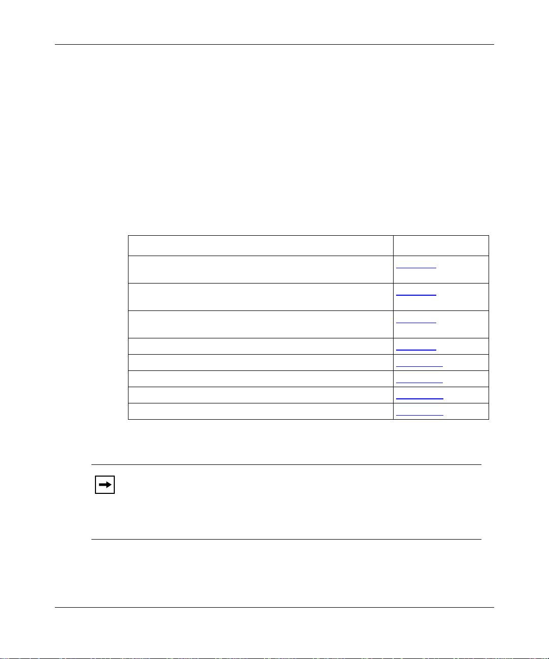
If you want to Go to
Physical ly install an AN or a 12-port ANH router and attach
communications equipment.
Physically install an 8-port ANH router and attach
communications equipment.
Connect the AN or ANH to t he netwo rk using o ne of the sof twar e
configuration options.
Operate the AN or ANH and interpret the LEDs. Chapter 4
Configure the AN or ANH for Netboot or Directed Netboot. Appendix A
Use Local Boot (the Quick-Start procedure). Appendix B
Review the AN or ANH technical specifications. Appendix C
Review the requirements for European operati on. Appendix D
The 12-port ANH router has the same base module and connectors as
Note:
Chapter 1
Chapter 2
Chapter 3
the AN router. The term AN, when used in this guide, includes the 12-port
ANH, unless stated otherwise. Instructions for the 8-port ANH router
generally differ and are described separately. The term AN/ANH, without
reference to ports, means the AN, the 12-port ANH, and the 8-port ANH.
114113-B Rev. 00
xxi
Page 22

Installing and Operating BayStack AN and ANH Routers
.
.
Before You Begin
Before installi ng the AN or ANH, ensure that all net work wiring has been
installed on the premises using standard cable-system practic es.
Before turning on the AN or ANH for the first time, cont act your network
administrator to det ermine which software configur ation option to use.
Conventions
angle brackets (< >) Indicate that you choose the text to enter based on the
description inside the brac ke ts. Do not type the
brackets when entering the command.
Example: if command syntax is
you enter
ping 192.32.10.12
<ip_address>
ping
,
bold text
Indicates text tha t you need to ent er, command names,
and buttons in menu paths.
Example: Enter
Example: Use the
wfsm &
dinfo
command.
Example: ATM DXI > Interfaces > PVCs identifies th e
PVCs button in the window tha t appears when you
select the Interfaces option from the ATM DXI menu.
brackets ([ ]) Indicate optional elements. You can choose none, one,
or all of the options.
.
ellipsis points Horizontal (. . . ) and v ertic al ellipsis points ind icate
()
omitted information.
italic te xt Indicates variable values in command syntax
descriptions, new terms, file and directory names, and
book titles.
quotation marks (“ ”) Indicate the title of a chapter or section within a book.
screen text
Indicates data that appears on the screen.
Example:
Set Bay Networks Trap Monitor Filters
separator ( > ) Separates menu and option names in instructions and
internal pin-to-pin wire connections.
Example: Protocols > AppleTalk identifies the
AppleTalk option in the Protocols menu.
xxii
114113-B Rev. 00
Page 23

About This Guide
Example: Pin 7 > 19 > 20
|
vertical line (
) Indicates that you enter only one of the parts of the
command. The vertical line sep arates choices. Do not
type the vertical line when enter ing the command.
Example: If the command syntax is
Acronyms
show at routes
show at routes
ANSI American National Standards Institute
AUI Attachment Unit Interface
BootP Bootstrap Protocol
BRI Basic Rate Interface
CCITT Internati onal Telegraph and Telephone Consultative Committee
(now ITU-T)
CSMA/CD carrier sense multiple access/collision detection
CSU channel service unit
CTS clear to s en d
DCD data carrier detect
DCE data communications equipment
DCM data collection module
DLCMI data link control management interface
DSR data set ready
DSU data ser vice unit
DTE data terminal equipment
DTR data terminal ready
EIA Electr on i c I ndu s t ries Asso ci at io n
GUI graphical user interface
HDLC high-le vel data link control
IEEE Institute of Electrical and Electronic Engine ers
IP Internet Protocol
ISDN Integrated Services Digital Network
ISO International Organization for Standardization
nets
|
, you enter either
show at nets
or
, but not both.
114113-B Rev. 00
xxiii
Page 24

Installing and Operating BayStack AN and ANH Routers
ITU-T International Telecommunications Union-Telecommunication
Standardization Sector
LAN local area network
LED light-emitting diode
MAC media access control
MAU me d ia access unit
MDI media-dependent interface
MDI-X media-dependent interface with crossover
NBMA nonbroadcast multiaccess
NEMA National Electrical Manufacturers Association
NVFS nonvolatile file sy stem
OCU office ch a n n el unit
OSI Open Systems Interconnection
PCMCIA Personal Computer Memory Card Internati onal Association
RLSD received line s ig n al dete ct i on
RTS request to send
SMDS Switched Multimegabit Data Service
SNMP Simple Network Management Protocol
SQE signal quality error
STP shielded twisted pa ir
TCP/IP Transmissi on Control Protocol/In ternet Protocol
TFTP Tr ivial File Transfer Proto col
TPE twisted pair Ethernet
UTP unshielded twisted pair
WAN wide area network
xxiv
114113-B Rev. 00
Page 25

Bay Networks Technical Publications
You can now print technical manuals and release notes free, directly from the
Internet. Go to support.baynetw ork s.c om/library/tpubs. Find the Bay Networks
products for which you nee d documen tation. Then locat e the spe cif ic ca tego ry and
model or version for your hardwa re or software product. Using Adobe Acrobat
Reader, you can open the manuals and release notes, search for the sections you
need, and print th em on most st andard printe rs. You can do wnload Ac robat R eader
free from the Adobe Systems Web site, www.adobe.com.
Documentation s ets and CDs are available through your loca l B ay Networks sales
off ice or account representative.
Bay Networks Customer Service
You can purchase a support contract from your Bay Networks distributor or
authorized reselle r, or directly from Bay Networks Ser vices. For information
about, or to purchase a Bay Networks ser vice contract, either call your local Bay
Networks fie ld sales office or one of the following numbers:
About This Guide
114113-B Rev. 00
Region Telephone number Fax number
United States and
Canada
Europe 33-4-92-96-69-66 33-4-92-96-6 9-96
Asia/Pacific 61-2-9927-8888 61-2-9927-8899
Latin America 561-988-7661 561-988-7550
800-2LANWAN; then enter Express Routing
Code (ERC) 290, when prompte d, to
purchase or renew a service contract
978-916-8880 (direct)
978-916-3514
Information about custom er service is also available on the World Wide Web at
support.baynetworks.com.
xxv
Page 26

Installing and Operating BayStack AN and ANH Routers
How to Get Help
If you purchase d a se rvi ce con t ract fo r your Bay Networks product from a
distributor or authorized reseller, contact the technical support staff for that
distributor or reseller for assistance.
If you purchased a Bay Networks service program, call one of the following Bay
Networks Technical Solutions Centers:
T echnical Solutions Center T elephone number Fax number
Billerica, MA 800-2LANWAN 978-916-3514
Santa Clara, CA 800-2LANW AN 408-495-1188
Valbonne, France 33-4-92-96-69-68 33-4-92-96-69-98
Sydney, Australia 61-2-9927-8800 61-2-9927-8811
Tokyo, Japan 81-3-5402-0180 81-3-5402-0173
Bay Networks Educational Services
xxvi
Through Bay Netw orks Ed ucati onal Servic es, you can a tt end cla sses a nd purcha se
CDs, videos, and computer -based training programs about Bay Networ ks
products. Training programs can take plac e at your site or at a Bay Networks
location. For more information about training progr ams, call one of the following
numbers:
Region T elephone number
United States and Canada 800-2LANWAN; then enter Express Routing Code (ERC)
282 when prompted
978-916-3460 (direct)
Europe, Middle East, and
Africa
Asia/Pacific 61-2-9927-8822
Tokyo and Japan 81-3-5402-7041
33-4-92-96-15-83
114113-B Rev. 00
Page 27
Chapter 1
Installing the BayStack AN
This chapter describe s how to install the BayStack Access Node (AN) router and
the 12-port BayStack Access Node Hub (ANH) router and prepare for software
installati on. F or information about installing the 8-port BayStack ANH, go to
Chapter 2
Note:
the AN router. The term AN, when used in this guide, includes the 12-port
ANH, unless stated otherwise. Instructions for the 8-port ANH router
generally differ and are described separately. The term AN/ANH, without
reference to ports, means the AN, the 12-port ANH, and the 8-port ANH.
.
The 12-port ANH router has the same base module and connectors as
114113-B Rev. 00
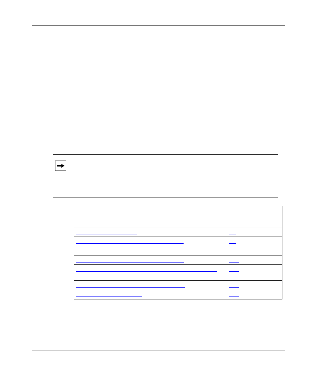
Topic Page
Overview of the AN and 12-Port ANH Hardware
Preparing to Install the AN 1-3
Installing the PCMCIA Memory Card Protector 1-6
Installing the AN 1-10
Connecting Communications Cables to the AN 1-15
Connecting the 12-Port ANH Ethernet Repeater Ports to the
Network
Connecting a Managemen t Consol e or Modem 1-24
Connecting the Power Cable 1-31
1-2
1-20
1-1
Page 28

Installing and Operating BayStack AN and ANH Routers
The installation instructions in this chapter assume that wiring is
Note:
already installed on the premises using standard cable system practices. Your
installati on procedure may differ slightly, depending on your cable system.
Overview of the AN and 12-Port ANH Hardware
The BayStack AN router is a low-end multiprotocol router/bridge or
router/bridge/hub that provides both LAN and WAN connectivity. It is a
cost-ef fective option for branch off ices with minimal space and power resources.
The AN product line off ers the following networ k interface configura tions:
• Single Ethernet/Dual Synchronous
• Single Token Ring/Dual Synchronous
• Single Ethernet/Single Token Ring/Dual Synchronous
In addition, the AN can include the foll owing upgrade options:
• Integrated Services Digital Network/Basic Rate Inte rface (ISDN BRI/ST or
ISDN BRI/U)
• 56/64K DSU/CSU adapter module
• Third synchronous interface
• Additional token ring interface
• Second Ethernet interface
• N11 RMON data collection module (DCM)
• FT1/T1 DSU/CSU adapter module
1-2
For technical specifications of the AN models, refer to Appendix C
.
114113-B Rev. 00
Page 29

Preparing to Install the AN
Before beginning the installation, verify the following information:
• Your AN shipment is complete and undamaged.
• You have the proper tools and equipment.
The sections that follow provide information to help you prepare for installation
You should also make sure that your installation site meets all AN site
requirements. Refer to Appendix C
requirements of the AN.
Verifying Shipment Contents
Verify that the items you recei v e matc h the it ems in th e packing l ist atta ched to th e
shipping container.
Inspect all items f or shipping damage.
1.
Installing the BayStack AN
for the physic al, electrical, and e nvironmental
Caution:
Check the AN for any damag e to t he ports on the back panel. If you
detect damage, do not install the AN. Call your local Bay Networks Technical
Solutions Center as described in “About This Guide
Make sure your shipping package contains the following items:
2.
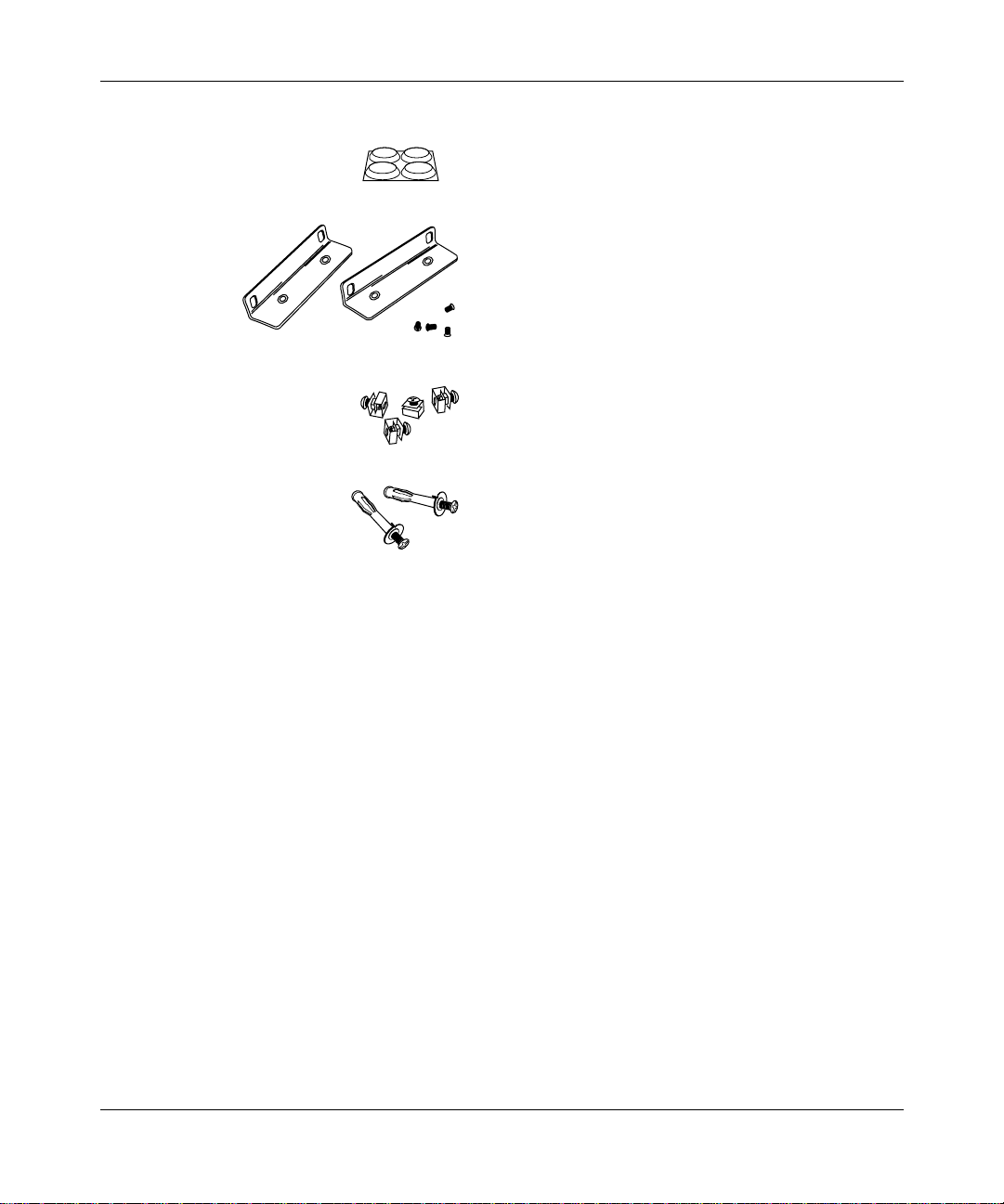
• Mounting hardware (Figure 1-1)
.
• Power cable and console/modem cable kit (Figure 1-2)
• Memory card protector (Figure 1-3)
.
.”
.
• Any network cables ordered with the router . I f you do not have the
appropriate network cables, contact your network administrator.
• Warranty information.
• This guide.
114113-B Rev. 00
1-3
Page 30
Installing and Operating BayStack AN and ANH Routers
Four rubber feet
Two flange backets
(for installing the AN in an
equipment rack or
mounting it on a wall)
Four cagenuts with screws
(for installing the AN in an
equipment rack)
2 wall anchors
(for mounting the AN on a wall)
Figure 1-1. AN Mounting Hardware
AN0001A
1-4
114113-B Rev. 00
Page 31

Installing the BayStack AN
Power cable
For connecting to a grounded power outlet
DB-25 receptacle
null nodem adapter
DB-9 receptacle
to DB-25 plug
serial cable
For connecting an optional terminal
or modem to the console service port
AN0002A
Figure 1-2. AN Cables
AN0036A
Figure 1 -3 . Me m ory Card Protecto r
Supplying Tools and Equipment
To install the AN, you need the following tools and equipment:
• Phillips screwdriver, for attaching brackets to mount the AN in an equipment
rack or on a wall
• Flat-tip screwdriver, for installing the memory card protector and attaching
network cables to the AN
• Electric drill, if you intend to mount the AN on a wall
114113-B Rev. 00
1-5
Page 32

Installing and Operating BayStack AN and ANH Routers
• Equipment rack that complies with the requirements listed in Appendix C, if
you intend to install the AN in a rack
• VT-100 or equivalent console, when using Netboot, Directed Netboot, or
Local Boot to start the router
Installing the PCMCIA Memory Card Protector
The AN ships with a memory card protector that you can install in the flash
memory card receptacle to prevent removal of a memory card. After the protector
is installed, you must remove the AN enclosure to remove or replace a PCMCIA
card.
To install the memory card protector:
Remove the AN enclosure.
1.
Attach the protector.
2.
Install the flash memory card.
3.
Replace the AN enclosure.
4.
The following sections describes these tasks.
Removing the AN Enclosure
To install the memory card prote c tor, remove the AN enclosure from the
component tray and attach the metal protector to the front-panel
memory card slot.
You need a flat-tip screwdriver or similar tool to install or remove the protector.
Caution:
AN enclosure is in place could damage an installed PCMCIA memory card.
1-6
Attempting to in stall or r emo ve the memory c ard prot ector whi le the
114113-B Rev. 00
Page 33

Installing the BayStack AN
To remov e the AN enclosur e from the component tray:
Locate and unscrew the two captive thumbscrews on the back panel
1.
(Figure 1-4
).
Caution:
Electrostatic discharge can damage the hardware when the AN
enclosure is removed. To protect your equipment fr om damage, place the AN
on an antistati c mat or stat ic-free surface before removing the enclosure.
XCVR
UTP
CONSOLE
TX
RX
CL
RST
RLSD2
Figure 1-4. AN Back-Panel Thumbscrews
Grasping both sides of the AN enclosur e, pull it away from the back
2.
panel and component tray until you can remove it.
Move the metal enclosure away from the component tray; do not touch the
exposed base module.
CO M 2
COM 1
RLSD1
Captive thumbscrews
U
L
U
L
50-60 Hz
1.0-0.5A
100-240V
AN0083A
Attaching the Protector
To attach the PCMCIA card protector to the front-panel memory card slot on the
AN enclosure:
Move the AN enclosure so that you have access to the front panel
1.
(Figure 1-5)
114113-B Rev. 00
.
1-7
Page 34

Installing and Operating BayStack AN and ANH Routers
POWER
RUN
BOOT
DIAG
Access Node
Memory card slot
Figure 1-5. AN Front Panel
Holding the protect or horizontally (Figure 1-6), insert two holding tabs
2.
into the AN enclosure card slot cutout. Rest the corresponding outer
flange against the outside of the enclosure.
Outside flange (1 of 2)
Inside holding tab
(1 of 4)
AN0084A
Figure 1-6. Tabbed Edges and Flanges on Memory Card Protector
The bottom of the enc losure cutout should be between one outside flange and
one pair of inside holding tabs.
Warning:
Do not hold or press on the metal edges of the protector; the edges
are very sharp.
AN0088A
1-8
Using a screwdri ver or similar tool, press down firmly on the top two
3.
holding tabs until they snap inside the cutout.
The protector is properl y insta lled when both outer flanges rest securely
against the front panel (Figure 1-7)
.
114113-B Rev. 00
Page 35

RUN
BOOT
POWER
DIAG
Figure 1-7. Installed Memory Card Protector
Installing the Flash Memory Card
To install the flash memory car d:
Position the card (Figure 1-8) with the labe l faci ng up and the I N SE RT
1.
arrow pointing toward the memory card receptacle (refer to Figure 1-5
on the AN component tray.
Installing the BayStack AN
Access Node
AN0085A
)
114113-B Rev. 00
INSERT
AN0060A
Figure 1-8. Flash Memory Card
Insert the card into the receptacle.
2.
Gently push the card until it f its snugly into place.
3.
1-9
Page 36

Installing and Operating BayStack AN and ANH Routers
Replacing the AN Enclosure
To replace the AN enclosure:
Grasping both sides of the AN enclosure, align the bottom edges with the
1.
component tray.
Push the enclosure toward the back panel.
2.
Fasten the two captive thumbscrews on the back panel (refer to
3.
Figure 1-4).
In this guide, illustr ations of the AN front pane l sho w the rout er withou t
Note:
the memory card protector installed. However, the front panel of your AN
should look like the one shown in Figure 1-7
Installing th e AN
You can install the AN in any of the following ways:
• Position the AN on a flat, sturdy surface.
.
• Install the AN in an equipment rack.
• Mount the AN on a wall.
The followi ng sections provide instruct ions for each option. Refer to the
appropriate section when positioning your AN.
Positioning the AN on a Flat Surface
To position the AN on a flat surface:
Make sure the surface is large enough for the AN to operate properly.
1.
The surface must be sturdy enough to support the combined weight of the AN
and any cables you connect.
Peel the paper backing off the four rubber feet supplied with the AN and
2.
attach them to the embossed feet on th e botto m of the A N .
Set the AN in the chosen location.
3.
You can now connect the network cables to your AN. Go to “Connecting
Communications Cables to the AN,” later in this chapter.
1-10
114113-B Rev. 00
Page 37

Installing the AN in a Rack
For thi s procedure, you ne ed the contents of the AN shipment, an equipment rack,
and a Phillips scre wdriver.
To install the AN in a rack:
Attach a flange bracket to each side of the AN (Figure 1-9) as follows:
1.
Align the flange holes with the AN mounting holes.
a.
Insert a flange scre w thr ough each flange hole and into the AN.
b.
Tighten each flan g e screw w ith a Phi l lip s screw dr iver.
c.
Installing the BayStack AN
Access Node
Run
Boot
Diag
Power
114113-B Rev. 00
Screws
(4 places)
Figure 1-9. Attaching Flange Brackets to the AN
Place the AN in the rack, aligning the flange holes with the holes in the
2.
front vertical supp orts o f the rack (Figure 1-10).
Insert a cagenut screw through each flange hole and into the
3.
corresponding holes in the front vertical supports of the rack.
If the rack does not ha v e thr eaded ra il hole s, use the c agenuts a long with
Note:
the cagenut screws.
Tighten each ca genut screw with a Phillips screwdriver.
4.
AN0003A
1-11
Page 38

Installing and Operating BayStack AN and ANH Routers
RUN
BOOT
POWER
DIAG
Cagenut screw
(4 places)
Rail without
threaded holes
AccessNode
Use cagenut
Figure 1-10. Installing the AN in a Rack
You can now connect the network cables to your AN. Go to “Connecting
Communications Cables to the AN,” later in this chapter.
Mounting the AN on a Wall
When mounting the AN on a wall, keep the following in mind:
• Make sure that the wall is at least 3/8 inch (in.) (0.96 cm) thic k and is made of
sheetrock or wood.
• You need the following equipment:
-- Electric drill
1-12
AN0004A
114113-B Rev. 00
Page 39

Installing the BayStack AN
-- Phillips screwdriver
-- Two wall-mount anchors
To mount the AN on a wall:
Drill two 5/16-in. (0. 8 cm) holes in the wall 5-1/4 in. (13.34 cm) apart, at
1.
least 3 feet (ft.) (0.915 m) above the floor.
Insert one wall-mount anchor into each hole.
2.
Tighten the anchors with a Phillips screwdriver.
3.
Back the head of each screw out 1/8 in. (0.32 cm) from the wall.
4.
Hang the AN on the wall by aligning the keyhole cutouts on the back of
5.
the AN with the protruding screw heads (Figure 1-11).
114113-B Rev. 00
1-13
Page 40

Installing and Operating BayStack AN and ANH Routers
Access Node
RUN
BOOT
DIAG
POWER
1-14
Rubber feet
AN0005A
Figure 1-11. Mo unting the AN on a Wall
114113-B Rev. 00
Page 41

Installing the BayStack AN
Connecting Communications Cables to the AN
Figure 1-12 illustra tes a sample cable config urati on. To connect network cables to
the back of the AN or 12-port ANH:
Connect the appropriat e network cables to the communications ports on
1.
the back of the router (Figure 1-12)
For some cables, you may need a flat-t ip screwdriv er to secure the connector
in place.
.
Appendix C
describes the communications ports tha t a re available on the
different AN and 12-port ANH models.
XCVR
UTP
Ethernet
transceiver
Modem,
console
or PC cable
ThinNet cable
Figure 1 -1 2. Plugging Cabl es in to th e A N
CONSOLE
TX
RX
CL
RST
Token ring
cable
MAU
Synchronous
P/N 1Ø7913-24
S/N ATX15Ø8
MODEL 22ØØ2
RCVR
NSRT
WFAIL
RLSD1RLSD2
cables
TM
ACCESS NODE (AN)
This equipment complies with the requirements in part 15 of FCC rules for Class A computing device
Operation of the equipment in a residential area may cause unacceptable interference to radio and TV
reception requiring the operator to take whatever steps are nessessary to correct the interference.
COM 1
COMMUNICATIONS SERVER
MADE
S403
U
LISTED EDP
IN
L
EQUIPMENT
U.S.A.
L6 4490313
U
L
100-240V
50-60 Hz
1.0-0.5A
AN0089A
114113-B Rev. 00
Connect the network cables to the ph ysical network.
2.
Contact your network admin istrator or see the Cable Guide if you need
assistance in connecting the router to the physical network devices or if you
are missing any netw ork cables.
1-15
Page 42

Installing and Operating BayStack AN and ANH Routers
Connecting to a 56/64K DSU/CSU Interface
you upgraded the AN or 12-port ANH with a 56/64K DSU/CSU adapter
If
module,
To connect to a 56/64K DSU/CSU interface:
1.
you can connect a 56/64K DSU/CSU cable to the router as follows:
Insert the 56/64K DSU/CSU cable connector into the DSU/CSU interface
labeled DDS (Figure 1-13).
U
L
U
L
XCVR
UTP
CONSOLE
TX
RX
CL
RST
RLSD2
CO M 2
Synchronous cables
Complies with FCC Rules Part 68
DDS
Reg. Number 4P8USA-24230-DE-N
56K/64K
DSU/CSU
CD
Tx
Rx
Test
56/64K DSU/CSU
Figure 1-13. Connecting a 56/64K DSU/CSU Cable
Connect the oth er end of the cable to a digital line (for example, a digital-
2.
line wall jack that connects to an office channel unit [OCU]).
RLSD1
COM 1
100-240V
50-60 Hz
1.0-0.5A
AN0131A
1-16
114113-B Rev. 00
Page 43

Connecting an FT1/T1 DSU/CSU Cable
If
you upgraded the AN or 12-port ANH with an AN/ANH FT1/T1
DSU/CSU adapter module, you can connect the FT1/T1 DSU/CSU cable to the
back of the AN or ANH as follows:
Plug the FT1/T1 DSU/CSU cable into the RJ-48C connector
1.
(Figure 1-14).
Installing the BayStack AN
U
L
U
L
XCVR
UTP
FT1/T1
DSU/CSU
TX
RX
CL
CONSOLE
Complies with FCC Rules Part 68
Reg. Number 4P8USA-31445-DE-N
Red Alm
Yel Alm
Loop
Sync
RST
RLSD2
CO M 2
Figure 1-14. Connecting an FT1/T1 DSU/CSU Cable
Connect the other end of the cable to the T1 communication device.
2.
RLSD1
COM 1
100-240V
50-60 Hz
1.0-0.5A
AN0123A
114113-B Rev. 00
1-17
Page 44

Installing and Operating BayStack AN and ANH Routers
Connecting an ISDN Cable
XCVR
ISDN-BRI
ISDN BRI
cable
If you upgraded
module, y
Plug the ISDN cable into the ISDN-BRI connector (Figure 1-15).
1.
UTP
TX
RX
CL
the AN or 12-port ANH with an ISDN Basic Rate Interface (BRI)
ou can
connect an ISDN BRI cable to the back of the router as follows:
CONSOLE
RST
RLSD2
CO M 2
RLSD1
COM 1
Synchronous cables
U
L
U
L
100-240V
50-60 Hz
1.0-0.5A
AN0130A
Figure 1-15. Connecting an ISDN BRI Cable
Connect the other end of the cable to the ISDN communications devi ce.
2.
Connecting Synchronous Cables
To connect from one to three synchronous interface cables to the back of the AN
or 12-port ANH:
Locate the RS-232, RS-422, V.28, V.35, or X.21 interface cable.
1.
For information about these cables, see the
Connect the cable to the back panel port labeled COM1, COM2, or
2.
COM3 (Figure 1-16).
1-18
Cable Guide
.
114113-B Rev. 00
Page 45
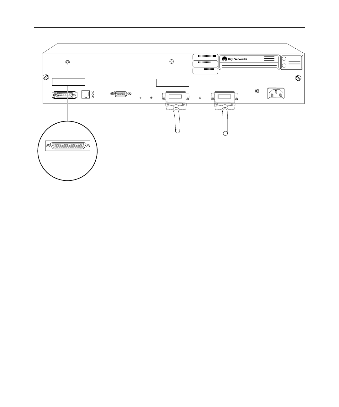
Installing the BayStack AN
U
L
U
L
XCVR
UTP
CONSOLE
TX
RX
CL
RST
RLSD2
CO M 2
COM 1
RLSD1
Synchronous cables
Third synchronous
interface cable
Figure 1-16. Connecting Synchronous Cables to COM1, COM2, or COM3
Secure the screws on th e cabl e’s COM con nector.
3.
Connect the other end of each cable to the appropriate communications
4.
equipment.
100-240V
50-60 Hz
1.0-0.5A
AN0129A
114113-B Rev. 00
1-19
Page 46

Installing and Operating BayStack AN and ANH Routers
Connecting the 12-Port ANH Ethernet Repeater Ports to the Network
This section is specific to the 12-port ANH and cannot be applied to an
Note:
AN router. See “Connecting Communications Cables to the AN” for
connection information common to both router types.
Figure 1-17 shows the 12-port ANH router with dual synchronous interfaces.
Ethernet repeater ports
XCVR
MCI
Link
Link
Link
Link
Link
Part
Part
12
UTP
TX
RX
CL
Part
11 10 9 8 7 6 5 4 3 2 1
CONSOLE
RST
RLSD2
Link
Part
Part
Part
LINK
COM 2
Link
Link
Link
Link
Link
Part
RLSD1
Part
Part
Part
COM 1
Link
Part
Part
U
L
U
L
100-240V
50-60 HZ
1.0-0.5 SA
1-20
Synchronous interfaces
AN0007A
Figure 1-17. 12-Port ANH with Dual Synchronous Interfaces
When connecting cables to the Ethernet repeater ports, note the following:
• The 12-port ANH allows simultaneous connection to any and all of the 12
Ethernet repeate r ports.
• Each repeater port ships with an internal c rossover connectio n. This mea ns
that you can use a straight-th rou gh cable when connecting to other network
resources (for exa mple, workstations or other nonrepeating devices).
• A switch on the repeater port module lets you adjust port 12 from a
crossed-over to a straight-through configuration when linking to other hubs.
See the next section fo r more info rmat ion about the crossover switch.
• As a repeater, the 12-port ANH transmits the same information over all
Ethernet ports simulta neously.
114113-B Rev. 00
Page 47

Using the Crossover Switch
The 12-port ANH ha s an in ternal cross ove r swit ch tha t af f ects r epeate r port 12 . By
default, the crossover switch is set to the crossover position.
You can adjust the crossover switch to change port 12 from a crossed-over
configuration (media-dependent interface with crossover, or MDI-X) to a
straight-thr ough configuration (media -dependent interface, or MDI), as follows:
• In MDI-X (crossover) mode, transmit and receive signal connections are
reversed.
• In MDI mode, the port transmits and receives straight-through signals.
You can use port 12 in MDI mode to connect (daisy-chain) the ANH to another
10BASE-T MDI-X port using unshielded twisted pair (UTP) straight-through
RJ-45 patch cables (instead of a special crossover cable ). You can interconnect as
many as four hub units using the Ethernet repeater ports.
The followi ng sections explain ho w to:
• Access and adjust the internal crossover switch.
Installing the BayStack AN
• Connect the 12-port ANH to another 10BASE-T hub, such as the Bay
Networks Model 2800 Hub.
Accessing and Adjusting the Crossover Switch
To access and adjust the crossover switch:
Loosen the two captive thumbscrews on the ANH back panel (refer to
1.
Figure 1-4).
Grasping both sides of the ANH enclosure, pull it away from the back
2.
panel and component t ray until you can easily reach t he crossover switch
(Figure 1-18).
Adjust the crossover s wit ch to either the crossover or stra igh t-t hrou gh
3.
position (Figure 1-18)
114113-B Rev. 00
.
1-21
Page 48

Installing and Operating BayStack AN and ANH Routers
Straight-through
position
Crossover
position
1-22
Figure 1-18. Accessing and Adjusting the Crossover Switch
Note:
By default, the switch is in the crossover position.
Slide the ANH back panel into the chassis.
4.
Tighten the thum bs crew s.
5.
114113-B Rev. 00
AN0008A
Page 49

Installing the BayStack AN
Connecting the 12-Port ANH to Other 10BASE-T Hubs
If you plan to daisy-chain a 12-port ANH to other repeater/hub systems, you must
make sure your network complies with Ethernet operating standards. For more
information, contact your network administrator.
In addition to a 12-port ANH, you can also connect an 8-port ANH to
Note:
other 10BAS E-T hubs as described in “Connecting the ANH to Other
Repeaters/Hubs” in Chapter 2. You cannot make such a connection, however,
with an AN router.
To determine whether you need to use a crossover cable or a straight-thr ough
cable to interconnect hub units, consider the following:
• If the Ethern et UT P por ts on b o th hubs are i n MD I mod e, use a cro ssover
cable.
• If the UTP ports on both hubs are in MDI-X mode, use a crossover cable.
• If the UTP port on one hub is in MDI mode, and the UTP port on the other
hub is in MDI-X mode, use a straight-through cable.
114113-B Rev. 00
For example , suppose you want to link your 12-port ANH to a Bay Networks
Model 2800 Hub and you have only a straight-through cable. You could do the
following:
Set the crossover switch to MDI mode on the ANH.
1.
Connect one end o f the s trai g ht- thro ugh ca bl e to port 1 2 on th e ANH .
2.
Connect the other end of the straight-through cable to any MDI-X port
3.
on the Bay Networks Model 2800 Hub.
Or, you could set the appropriate port on the Model 2800 Hub to MDI mode and
connect the straight -through cable from that port to any port on the 12-port ANH
(including port 12 if the crossover switch is in the default position).
Figure 1-19
sho ws a 12-port ANH conn ected to a Bay Networks Model 2800 Hub.
1-23
Page 50

Installing and Operating BayStack AN and ANH Routers
12-Port ANH
LINK
COM 2
RST
RLSD2
RLSD1
XCVR
12
11 10 9 8 7 6 5 4 3 2 1
UTP
CONSOLE
TX
RX
CL
Bay Networks Model 2800A Ethernet Hub
COM 1
TM
ACCESS NODE (AN )
COMMUNICATIONS SERVER
This equipment complies with the requirements in part 15 of FCC rules for Class A computing device
Operation of the equipment in a residential area may cause unacceptable interference to radio and TV
reception requiring the operator to take whatever steps are nessessary to correct the interference.
P/N 1Ø6917-24 RØ4
S/N AEX12698
MODEL 2ØØØ2
MADE
S403
U
LISTED EDP
IN
L
EQUIPMENT
U.S.A.
L6 4490313
U
L
100-240V
50-60 Hz
1.0-0.5A
AUI Port
Partition
MIDI-X-MDI
AUI
MDI-X
Figure 1-19. Connecting an AN to a Bay Networks Model 2800 Hub
Connecting a Management Console or Modem
To connect an ASCII-based termi na l, a PC te rm inal em ula tor, or a modem to the
AN or 12-port ANH, use the back-panel console por t. Using a local terminal, you
can monitor t he resul ts of s tart up diagnos tics a nd set the boo t configuration. Usi ng
an attached modem, you can allow remote dial-in access to diagnostics.
To determine whether you need to connect a console to the AN or 12-port ANH,
contact your network administrator to find out which software configuration
option (EZ-Insta ll, Netb oot, Direc ted Netboot, or Local Bo ot) is best f or your site.
Refer to Chapter 3, “
software conf iguration options.
Starting the AN and ANH” for information about the
LattisLinkHub 2800A
AN0009A
1-24
114113-B Rev. 00
Page 51

Although you do not need a console or modem connection to use EZ-Install, Bay
Networks strongly recommends that you connect a console or modem to the AN.
From the console or modem, you can issue commands to the AN and view
messages.
To use the Netboot, Directed Netboo t, or Local Boot software
Note:
configuration options, you must connect a console the first time you turn on
the AN, as described in Chapter 3.
Complete the steps in one of the following sections:
• Connecting a Terminal Console
• Connecting a PC Console
• Connecting a Modem
Connecting a Terminal Console
To connect a console, you need both piec es in the AN console/modem cable kit
(Order No. 110310) that shipped with the router (refer to Figure 1-2):
Installing the BayStack AN
114113-B Rev. 00
• Serial console/modem cable with 9-pin receptacle to 25-pin plug connectors
(Order No. 110307)
• Null modem crossover adapter with two 25-pin receptacle connectors (Order
No. 110308)
After you hav e the app ropriate equipment, complete the following steps:
Turn on and configure the console, using the paramet ers in Table 1-1.
1.
Refer to the console user manual for instructions.
Table 1-1. Console Parame te rs
Parameter Value
Baud rate 9600
Data bits 8
Stop bits 1
Parity None
1-25
Page 52

Installing and Operating BayStack AN and ANH Routers
Attach the null modem crossover adapter to the 25-pin cable connector
2.
(Figure 1-20).
Insert the screw s on the cab le connector into the recepta cle o n the
3.
adapter conn ector and tig hte n ea ch screw.
Console cable
Rotate to tighten screw
Screw receptacle
Null modem adapter
AN0010A
Figure 1-20. Attaching the Null Modem Adapter to the Console Cable
Insert the 9-pin receptacle end of the console cable into the CONSOLE
4.
port on the back panel of the AN (Figure 1-21).
COMM
U
L
U
L
CONSOLE
UTPXCVR
TX
RX
CL
COM 2
RST
COM 1
RSLD1RSLD2
100-240V
50-60 HZ
1.0-0.5 SA
20 mA PR
KB
1-26
Console cable plus
null modem adapter
AN0011A
Figure 1-21. Connecting a Terminal Console to the AN
114113-B Rev. 00
Page 53

Installing the BayStack AN
Attach the 25-pin receptacle connector on the combined cable and
5.
adapter to the terminal’s host connector.
The console is now connected to the AN. Go to “Connecting the Power Cable
the end of this chapter.
Connecting a PC Console
To connect a PC, you need both pieces in the AN console/mode m cable kit
(Order No. 110310) that shipped with the router (Figure 1-2):
• Serial console/modem cable with 9-pin receptacle to 25-pin plug connectors
(Order No. 110307)
• Null modem crossover adapter with two 25-pin receptacle connectors
(Order No. 110308)
You also need another st andard AT serial cable wi th a 25-pi n plug c onnec tor. After
you have the app rop riate equipment, complete the following steps:
Turn on and configure the PC concole, using the parameters in Table 1-1
1.
and the instructions in the PC documentation.
Turn off the PC.
2.
Insert the 9-pin receptacle end of the console cable into the CONSOLE
3.
port on the AN back panel (Figure 1-22).
Attach the null modem crossover adapter to the other end of the console
4.
cable, then tighten the screws (Figure 1-20).
” at
114113-B Rev. 00
Attach the 25-pin receptacle end of the cable-plus-adapter to the PC
5.
console cable’s 25-pin plug connector (Figure 1-22).
Connect the complete cable unit to the communications port on the back
6.
of the PC (Figure 1-22).
1-27
Page 54

Installing and Operating BayStack AN and ANH Routers
U
L
U
L
CONSOLE
UTPXCVR
TX
RX
CL
COM 2
RST
COM 1
RSLD1RSLD2
100-240V
50-60 HZ
1.0-0.5 SA
PC cable
Null modem adapter
Figure 1-22. Connecting a PC Console to the AN
The PC console is now connected to the AN. Go to “Connecting the Power Cable”
at the end of this chapter.
Connecting a Modem
A modem provides remote access to the AN for a network administr ator. Bay
Networks recommends that you con nect a modem in case the AN experie nces
system problems.
Note:
Netboot, Directed Netboot, and Local Boot require a terminal or PC
console connection. After the AN is on the network, you can replace the
console connectio n with a modem conn ectio n. When us ing EZ-Insta ll , you can
connect a modem to the AN be for e or aft er you conne ct the AN t o the netw ork.
1-28
Console cable
AN0012A
114113-B Rev. 00
Page 55

Installing the BayStack AN
To connect a modem to the AN, you need:
• AT (or Hayes) compatible modem
• Modem cable in the AN console/modem cable kit (Order No. 110307)
Do not use the null modem adapter (Order No. 110308) from the AN cable kit.
After you hav e the app ropriate equipment, complete the following steps:
Configure the mode m, us ing the pa rameters in Table 1-2.
1.
Refer to the modem user guide for instructions.
Table 1-2. M odem P arameters
Modem Signal/Parameter Value
Clear to send (CTS) On
Data terminal ready (DTR) Dependent on the modem type. Set DTR to
require the modem to answer incoming calls.
Data carrier detect (DCD) or RLSD On while carrier is present (the AN uses DCD to
detect modem connect and disconnect).
Data set ready (DSR) On
Ready to send (RTS) Ignore
Synchronous/asynchronous mode Asynchronous
than 0).
n
rings with DTR active (n must be great er
AutoAnswer Set on
Local character echo Off
Supervisory functions Off
Baud rate 9600 (or less)
Data bits 8
Stop bits 1
Parity None
114113-B Rev. 00
Caution:
Do not connect a modem to the AN until you are certa in tha t the
modem is configur ed as described in Table 1-2. Connecting to the AN with an
improperly conf igured modem could cause the router to fail or lose data.
1-29
Page 56

Installing and Operating BayStack AN and ANH Routers
Insert the 9-pi n recep ta cle end of the modem ca bl e into the bac k-p a ne l
2.
CONSOL E port of the AN (Figure 1-23).
CONSOLE
UTPXCVR
TX
RX
CL
COM 2
RST
COM 1
RSLD1RSLD2
100-240V
50-60 HZ
1.0-0.5 SA
PHONE
DIAL
(LEASE
DWR
3810
U
L
U
L
NMS DTE
(LEASED)
3810
Modem cable
AN0013A
1-30
Figure 1-23. Connecting a Modem to the AN
Insert the 25- pin pl ug at the o the r end of the modem ca bl e into the
3.
modem’s RS-232 da ta communications port
.
The modem is now connected to the AN. Connect the po wer cable, as described
next.
114113-B Rev. 00
Page 57

Connecting the Pow er Cable
To connect the powe r cable:
Connect the power cable to the connector located on the far right of the
1.
AN back panel (Figure 1-24).
Installing the BayStack AN
Ethernet
transceiver
Danger:
Be sure that the power switch is in the OFF (0) position before you
connect the power cable to the outlet.
Connect the remote end o f the pow er ca ble to a grounded outlet.
2.
ACCESS NODE (AN)
COMMUNICATIONS SERVER
Power cable
XCVR
UTP
Modem,
console
or PC cable
ThinNet cable
P/N 1Ø7913-24
S/N ATX15Ø8
MAU
CONSOLE
TX
RX
CL
RST
Token ring
cable
MODEL 22ØØ2
RCVR
NSRT
WFAIL
RLSD1RLSD2
Synchronous
cables
This equipment complies with the requirements in part 15 of FCC rules for Class A computing device
Operation of the equipment in a residential area may cause unacceptable interference to radio and TV
reception requiring the operator to take whatever steps are nessessary to correct the interference.
COM 1
TM
MADE
S403
U
LISTED EDP
IN
L
EQUIPMENT
U.S.A.
L6 4490313
U
L
100-240V
50-60 Hz
1.0-0.5A
114113-B Rev. 00
AN0006A
Figure 1-24. Connecting the Power Cable
1-31
Page 58

Page 59

Chapter 2
Installing the BayStack 8-Port ANH
This chapter describes how to install the BayStack 8-port ANH router. Topics
include the follo wing:
Topic Page
Preparing to Install the 8-Port ANH
Installing the 8-Port ANH 2-7
Connecting Communications Cables 2-12
Connecting a Managemen t Consol e or Modem 2-21
Connecting the Power Cable 2-27
The installation instructions in this chapter assume that wiring is
Note:
2-2
already installed on the premises using standard cable system practices. Your
installati on procedure may differ slightly, depending on your cable system.
114113-B Rev. 00
2-1
Page 60

Installing and Operating BayStack AN and ANH Routers
Preparing to Install the 8-Port ANH
The installation of the 8-port ANH differs from that of an AN or 12-port ANH,
which is described inChapter 1, “Installing the BayStack AN.”
Before beginning the installation, verify the following information:
• Your shipment is complete and undamaged.
• You have the proper equipment and tools.
• Your installation site meets the physical, electrical, and environmental
requirements.
• You have the communication devices and the cables tha t you need to attach to
the ANH.
The sections that follow provide information to help you prepare for installation.
Verifying Shipment Contents
To verify your 8- port ANH shipment:
Inspect all items f or shippin g damage.
1.
2-2
If you detect any damage, do not install the ANH. Call the Bay Networks
Technical Solutio ns Center in your area, as described in “About This Guide.”
Verify that the items you received match the items on the packing list.
2.
The packing list is usually affixed to the shipping container.
The ANH shipping package contains the following items:
• One
• One
•Two
• Eight #6 Class B self-threading flathead
power cable
cable kit
console or modem. The console /modem cab le kit cont ai ns one 15-f oot AT
standard molded serial cable (with DB-9 receptacle to DB-25 plug
connectors) and one null modem crosso ver adapter (with DB-25 to DB-25
receptacle co nn ect ors ).
flange brac kets
mounting the ANH.
in an equipment rack).
for connecting the ANH to a power outlet.
(Order No. 110310) for connecting an optional local
with four #10 cagenut screws and washers for
screws
(for mounting the ANH
114113-B Rev. 00
Page 61

Installing the BayStack 8-Port ANH
• Four #6 Class B self-threading roundh ead screws (for mounting the ANH
on a wall).
• Four press-on rubber feet (for positioning the ANH on a flat surface).
Figure 2-1
illustrates the ANH shipping accessories.
114113-B Rev. 00
2-3
Page 62
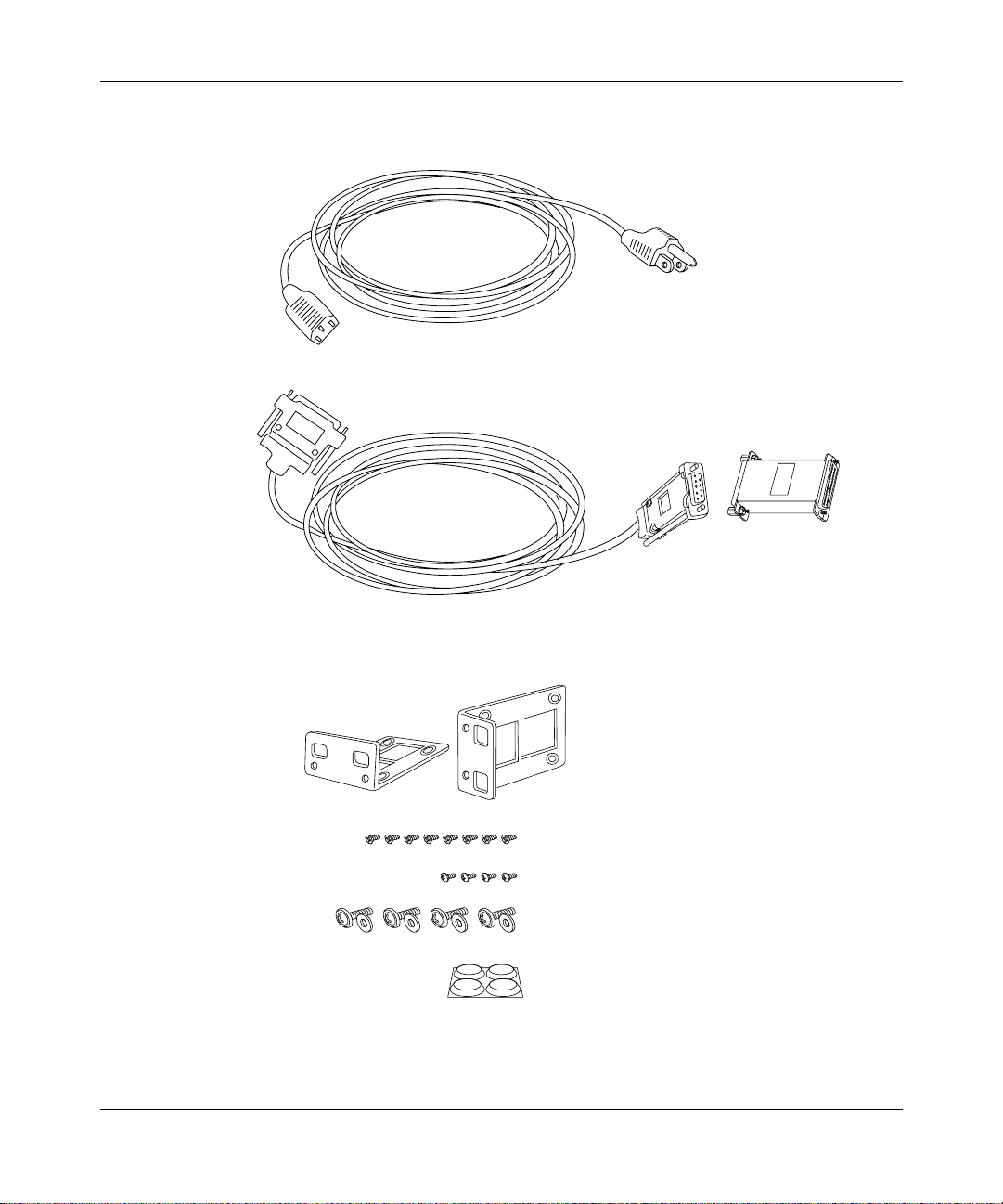
Installing and Operating BayStack AN and ANH Routers
For connecting to a grounded power outlet
Power cable
For connecting an optional terminal or
modem to the console service port
DB-9 receptacle
to DB-25 plug cable
DB-25 receptacle
null modem adapter
2-4
For installing the ANH in an
equipment rack or
mounting it on a wall
Two flange brackets
Eight #6 flathead screws
Four #6 roundhead screws
Four #10 cagenut screws and washers
Four rubber feet
AN0037A
Figure 2-1. Accessories in the ANH Shipping Container
114113-B Rev. 00
Page 63

Supplying Equipment
You may need items that are not included in the ANH accessory package. Before
installing the ANH hardware, ensure that you have all the cables, tools, and other
equipment you need.
Cables
Unless you specif ically ordered them, the Ethernet and synchron ous cables
required for your netw ork configuration are not included in the ANH accessory
package. If you do not have the proper cable s, contact your network administrator
or see the Cable Guide.
Management Console
You can attach an optional VT-100 console (or equivalent) to the ANH to monitor
the results of startu p diagn ostics and perform ma nual boot configurations, or you
can attach a ny AT compatible mode m to allow remote dial-in a ccess to diagnost ics
and configur ation.
Installing the BayStack 8-Port ANH
114113-B Rev. 00
To use the Netboot, Directed Net boot, or Local Boot configuration
Note:
options (see Chapter 3), connect a console the first time you turn on the ANH.
Mounting Hardware
To mount the 8-port ANH in an equipment rack, you need a Phillips sc rewdriver
and a rack that meets the following specifications:
• Heavy-duty steel construction
• Electronic Industries Association (EIA) standard hole-sp acing
• Width of 19 in. (48.26 cm) and depth of 24 in. (60.96 cm)
If the rack does not have threaded rail holes, you must supply cagenuts to use with
the cagenut screws (Figure 2-2)
.
2-5
Page 64

Installing and Operating BayStack AN and ANH Routers
Screw
Cagenut
AN0038A
Figure 2-2. Sample Cagenuts and Screws for Unthreaded Rack Rails
To mount the ANH on a wall, you need at least four wall-m ount anchor screws
(Figure 2-3).
AN0039A
Figure 2-3. Sample Wall-Mount Anchor Screw
Verifying Site Requirements
The installation site must provide sufficient space around the ANH to ensure
proper ventilation and access for servicing, as detailed in Table 2-1.
Table 2-1. I nstallation Space Requirements
Width Minimum Depth Depth for Servicing
19.25 in. (48.9 cm) 17. 25 in. (43.8 cm) 26.25 in. (66.7 cm)
In addition, the installation site must meet the electrical and environmental
specifications listed in Appendix C
Caution:
2-6
You must use grounded electrical power outlets with the ANH.
.
114113-B Rev. 00
Page 65

Installing the 8-Port ANH
When you are ready to install the 8-port ANH, you can do one of the following:
• Position the ANH on a flat, sturdy, horizontal surface.
• Install the ANH in an equipment rack.
• Mount the ANH on a wall.
The followi ng sections provide instruct ions for each option. Refer to the
appropriate section when positioning your ANH.
Positioning the ANH on a Flat Surface
To position the ANH on a flat surface, first apply the four press-on rubber feet to
the bottom of the ANH chassis.
Make sure that the surface is large enough for the ANH to operate properly and
sturdy enough to support the combined weight of the ANH and any cables you
connect.
Installing the BayStack 8-Port ANH
You can now connect the network cables to your ANH. Go to “
Communications Cables.”
Installing the ANH in a Rack
For this procedure, you need the following items:
• Four #10 cagenut screws and washers (shipped with the ANH)
• Two flange brackets and eight #6 flathead screws (shippe d with the ANH)
• Phillips screwdriver
• Standard equipment rack
If the rack does not ha v e threa ded rail ho les, you must supply a nd attac h
Note:
four cagenuts.
114113-B Rev. 00
Connecting
2-7
Page 66

Installing and Operating BayStack AN and ANH Routers
To install the 8-port ANH in a rack:
Attach a flang e br ac ket to eac h sid e of the A NH a s follows:
1.
Align the holes in the longer end of the bracket with the mounting
a.
holes near the front of the ANH (Figure 2-4).
Insert a #6 flathead screw through each hole and into the ANH.
b.
Tighten the 4 screws with a Phillips screwdriver.
c.
1234 5678
MDI-X/MDI
MDI-X
Screws
(4 places)
Power
Fault
Boot
DCD1 DCD2 <LAN>
Col
Reset
AUI
DCM AUI Part
Run
Console
Partition
12345678
Link
Screws
(4 places)
Access Node Hub
Figure 2-4. Attaching Flange Brackets to Install the 8-Port ANH in a Rack
Align the flange bracket holes with the holes in the front vertical supports
2.
of the rack (Figure 2-5)
.
2-8
AN0040A
114113-B Rev. 00
Page 67

Installing the BayStack 8-Port ANH
1
2
MDI-X/MDI
MDI-X
3
4
5
6
7
MDI-X
8
123
Partition
4
5
67
8
Link
Access Node Hub
Screws
(4 places)
Rail
Cagenut
If the rack rail is not threaded,
attach a cagenut (not supplied).
Figure 2-5. Installing the ANH in an Equipment Rack
Insert a cagenut screw through each bracket hole and into the
3.
correspondi ng ho l es in th e ra ck.
Tighten each ca genut screw with a Phillips screwdriver.
4.
You can now connect the network cables to your ANH. Go to“
Communications Cables.”
AN0041A
Connecting
114113-B Rev. 00
2-9
Page 68

Installing and Operating BayStack AN and ANH Routers
Mounting the ANH on a Wall
For this procedure, you need the following items:
• Two flange brackets and four #6 roundhead screws (shipped with the ANH)
• Four to eight wall anchor screws (not shipped with the ANH)
• Phillips screwdriver
The sides of the ANH include screw holes at both ends, provi ding three
Note:
ways to attach the brackets for wall-mounting. You can attach both brackets
towar d the front of the ANH, both brackets toward the back, or you can offset
the two brackets, as shown in Figure 2-6, for the most secure installation.
To mount the ANH on a wall:
Attach a flang e br ac ket to eac h sid e of the A NH a s follows:
1.
With the longer bracket piece lying flat, align the holes in the shorter
a.
end of the bracket with two of the mounting holes on the side of the
ANH (Figure 2-6).
Insert a screw through each hole and into the ANH.
b.
Tighten the 4 screws with a Phillips screwdriver.
c.
Back of ANH
Screws
(2 places)
Front of ANH
Figure 2-6. Attaching Flange Brackets to Install the 8-Port ANH on a Wall
Place the ANH with installed brackets against the wall to determine the
2.
location of the anchor screws (Figure 2-7).
2-10
Screws
(2 places)
Access Node Hub
AN0042A
114113-B Rev. 00
Page 69

Installing the BayStack 8-Port ANH
Access Node Hub
114113-B Rev. 00
AN0043A
Figure 2-7. Mounting the 8-Port ANH on a Wall
2-11
Page 70

Installing and Operating BayStack AN and ANH Routers
Insert 2 to 4 wall anchor screws through the holes in each flange bracket,
3.
and fasten each screw securely in the wall.
Connecting Communications Cables
Gather the communications eq uipment a nd cables that you will attach to the
ANH. If you do not have the prop er cables, contact yo ur network administrator or
see the Cable Guide. Appendix C describes the ANH cable interfaces.
Connecting an AUI Cable
Power
Fault
Caution:
Connecting the ANH A UI port directly to the A UI port on an
Ethernet stati on violates IEEE 802.3 standar ds. The AUI port is designed only
for connection to a transceiver.
To connect an Ethernet AUI transceiver cable to the front of the ANH:
Connect an Ethernet AUI drop cable to the port labeled AUI (Figure 2-8).
1.
The cable must hav e a female 15-pin D-SUB connector.
AUI interface
Console
Boot Run DCM AUI Part
Reset
DCD1 DCD2 <LAN> Col
AUI
1 234 5678
MDI-X/MDI
MDI-X
Partition
12345678
Link
AUI cable
Access Node Hub
AN0044A
Figure 2-8. Connecting an AUI Cable
Secure the AUI cable using the connector slide lock .
2.
Connect the other end of the cable to the transceiver device.
3.
2-12
114113-B Rev. 00
Page 71

Installing the BayStack 8-Port ANH
Connecting Ethernet Repeater Port UTP Cables
To connect UTP cables to the front-panel 10BASE-T repeater ports, attach the
UTP cables to the front-panel RJ-45 connectors (Ethernet repeater ports 1- 8), as
shown in Figure 2-9.
Ethernet repeater ports 1-8
with RJ-45 connectors
UTP cables
Figure 2-9. Connecting Repeater UTP Cables
Access Node Hub
AN0045A
114113-B Rev. 00
Using the MDI-X/MDI Switch
The 8-port ANH front panel includes an external MDI-X/MDI switch
(Figure 2-10)
that allows you to change transmit and receive signals for
10BASE-T repe ater port 1 from normal repeater input mode (media-dependent
interface with crossover, or MDI-X) to repeater cascade out (media-dependent
interface , or MDI) conf iguration. In MDI-X mode, transmit and receive signal
connections are re versed; in MDI mode, the port transmits and receives
straight-thr ough signals.
Wit h a standard (straight-through) UTP cable in port 1, press the switch in for
MDI operation.
With a crossover cable in port 1, keep the switch out for MDI-X operation.
2-13
Page 72

Installing and Operating BayStack AN and ANH Routers
Power
Console
Reset
Fault
Boot Run DCM AUI Part
DCD1 DCD2 <LAN> Col
AUI
1 234 5678
MDI-X/MDI
MDI-X
MDI-X/MDI
Figure 2-10. 8-Port ANH Front-Panel MDI-X/MDI Switch
Connecting the ANH to Other Repeaters/Hubs
You can use port 1 in an MDI configuration to connect to a 10BASE-T MDI-X
port on another router/hub/bridge device using UTP straight-through RJ-45 patch
cables (ins tead of a spe cia l crosso v er cabl e). You can interc onnect (daisy- chai n) as
many as four 8-port ANH or other hub systems.
Partition
12345678
Link
Access Node Hub
AN0056A
2-14
To determine whether you need to use a crossover cable or straight- through cable
to interconnect hub units, consider the following:
• If the Ethern et UT P por ts on b o th hubs are i n MD I mod e, use a cro ssover
cable.
• If the UTP ports on both hubs are in MDI-X mode, use a crossover cable.
• If the UTP port on one hub is in MDI mode, and the UTP port on the other
hub is in MDI-X mode, use a straight-through cable.
When you configure a network with multiple ANH (or other repeater/hub)
systems, you must comply with the following rules:
• Connect no more than four hubs.
• Make sure each UTP connection is no longer than 100 m (109.4 yards).
114113-B Rev. 00
Page 73

Installing the BayStack 8-Port ANH
• If a transceiver is connected to the AUI port, disable the signal quality error
(SQE) test function of the transceiver.
Power
Power
Fault
Fault
Power
Figure 2-11
Console
Boot Run DCM AUI Part
Reset
Fault
Reset
Reset
DCD1 DCD2 <LAN> Col
Port 1
set for straight-through
connection (MDI)
Console
Boot Run DCM AUI Part
DCD1 DCD2 <LAN> Col
Port 1
set for default (crossover)
connection (MDI-X)
Console
Boot Run DCM AUI Part
DCD1 DCD2 <LAN> Col
shows three ANH systems connected with straight-through cables.
AUI
1 234 5678
MDI-X/MDI
MDI-X
Port 1
Port 1
AUI
AUI
MDI-X/MDI
1 234 5678
MDI-X/MDI
1 234 5678
MDI-X
MDI-X
Partition
12345678
Link
to
Partition
12345678
Link
Port 2
to
Port 1
Partition
12345678
Link
Access Node Hub
Access Node Hub
Access Node Hub
Port 1
set for straight-through
connection (MDI)
AN0046A
Figure 2-11. Linking ANH Routers
Figure 2-12 shows an 8-port ANH linked with two other Ethernet hubs. A UTP
cable connects each MDI port to an MDI-X port on another hub.
114113-B Rev. 00
2-15
Page 74

Installing and Operating BayStack AN and ANH Routers
ANH repeater port 1 switch
set to MDI
Power
Fault
Reset
Console
Boot Run DCM AUI Part
DCD1 DCD2 <LAN> Col
AUI
UTP cable
Model 810M Hub
Port 8 switch
set to MDI-X
Figure 2-12. Linking Hubs
For more information, refer to “10BASE-T Repeater Ports” in Appendix C.
1 234 5678
MDI-X/MDI
Model 810
MDI-X
UTP cable
Port 1 switch
set to MDI
Model 810M Hub
Partition
12345678
Link
Access Node Hub
Model 810
AN0075A
2-16
114113-B Rev. 00
Page 75

Installing the BayStack 8-Port ANH
Connecting a Second Ethernet Interface UTP Cable
If you upgraded the 8-port ANH with a second Ethernet interface module, you can
connect a UTP cable to the back-panel UTP-2 port as follows:
Attach a UTP ca ble to the bac k-p a nel RJ -4 5 con nec to r (Figure 2-13).
1.
COM 2COM 3/Expansion
TX
RX
COL
UTP-2
Second Ethernet
UTP cable connector
Figure 2-13. Connecting a Second Ethernet Interface Cable
Connect the other end of the cable to the communication device.
2.
COM 1
AN0047A
114113-B Rev. 00
2-17
Page 76

Installing and Operating BayStack AN and ANH Routers
Connecting Synchronous Cables
To connect from one to three synchronous interface cables to the back of the
8-port ANH:
Locate the RS-232, RS-422, V.28, V.35, or X.21 interface cable.
1.
For information about these cables, see the Cable Guide.
Connect the cable to the back-panel port labeled COM1, COM2, or
2.
COM3 (Figure 2-14).
Your ANH may not have a third synchronous interface. The
Note:
COM3/Expansion port may be empty or contain another cable interface.
COM 2COM 3/Expansion
Synchronous cables
Third synchronous interface
cable connector
COM 1
AN0048A
Figure 2-14. Connect i ng Synchrono us Cables t o C OM1, COM2, or COM3
The orientation of the COM3 connector is reversed from that of the
Note:
other COM ports.
Secure the screws on th e cabl e’s COM con nector.
3.
2-18
114113-B Rev. 00
Page 77

Connect the other end of each cable to the appropriate communications
4.
equipment.
Connecting an ISDN Cable
Installing the BayStack 8-Port ANH
If you upgraded
the ANH with an IS DN Basic Rat e Interface (BRI) module, y
connect an ISDN BRI cable to the back of the ANH as follows:
Plug the ISDN cable into the ISDN-BRI connector (Figure 2-15).
1.
COM 2COM 3/Expansion
Synchronous cables
ISDN-BRI
ISDN BRI
cable connector
Figure 2-15. Connecting an ISDN BRI Cable
ou can
COM 1
AN0049A
114113-B Rev. 00
Connect the other end of the cable to the ISDN communication device .
2.
2-19
Page 78

Installing and Operating BayStack AN and ANH Routers
A
Connecting to a 56/64K DSU/CSU Interface
you upgraded the 8-port ANH with a 56/64K DSU/CSU adapter module,
If
can connect a 56/64K DSU/CSU cable to the ANH as follows:
Insert the 56/64K DSU/CSU cable connector into the DSU/CSU interface
1.
labeled DDS (Figure 2-16).
you
COM 3/Expansion
Rx
Test
CD
Tx
Complies with FCC Rules Part 68
Reg. Number 4P8USA-24230-DE-N
DDS
56K/64K
DSU/CSU
COM 2
COM 1
Figure 2-16. Connecting a 56/64K DSU/CSU Cable
Connect the oth er end of the cable to a digital line (for example, a digital-
2.
line wall jack that connects to an office channel unit [OCU]).
AN0127
2-20
114113-B Rev. 00
Page 79

Connecting an FT1/T1 DSU/CSU Cable
If
you upgraded the 8-port ANH with an AN/ANH FT1/T1 DSU/CSU adapter
module, you can connect the FT1/T1 DSU/CSU cable to the back of the ANH as
follows:
Plug the FT1/T1 DSU/CSU cable into the RJ-48C connector
1.
(Figure 2-17).
Installing the BayStack 8-Port ANH
COM 2
COM 3/Expansion
Red Alm
Yel Alm
Complies with FCC Rules Part 68
Reg. Number 4P8USA-31445-DE-N
Loop
Sync
FT1/T1
DSU/CSU
Figure 2-17. Connecting an FT1/T1 DSU/CSU Cable
Connect the other end of the cable to the T1 communication device.
2.
Connecting a Management Console or Modem
T
o connect an ASCII-based terminal, a PC terminal emulator, or a modem to the
use t
ANH,
he front-panel console port.
COM 1
AN0124A
114113-B Rev. 00
Using a local terminal, you can monitor the results of startup diagnostics and set
the boot configur ation. Using an attached modem, you can allow r emote dial-in
access to diagnostic s.
Note:
To use the Netboot, Directed Netboo t, or Local Boot software
configuration options, you must connect a console the first time you turn on
the ANH, as described in Chapter 3, “Starting the AN and ANH.”
2-21
Page 80

Installing and Operating BayStack AN and ANH Routers
Connecting a Terminal Console
To connect a console, you need both piec es in the ANH console/modem cable kit
(Order No. 110310) that shipped with the router (Figure 2-1):
• Serial console/modem cable with 9-pin receptacle to 25-pin plug connectors
(Order No. 110307)
• Null modem crossover adapter with two 25-pin receptacle connectors
(Order No. 110308)
After you hav e the app ropriate equipment, complete the following steps:
Turn on and configure the console, using the paramet ers in Table 2-2.
1.
Refer to the console user manual for instructions.
Table 2-2. Console Parame te rs
Parameter Value
Baud rate 9600
Data bits 8
Stop bits 1
Parity None
2-22
Attach the null modem crossover adapter to the 25-pin cable connector
2.
(Figure 2-18).
Insert the screw s on the cab le connector into the recepta cle o n the
3.
adapter conn ector and tig hte n ea ch screw.
Console cable
Rotate to tighten screw
Screw receptacle
Figure 2-18. Attaching the Null Modem Adapter to the Console Cable
Null modem adapter
AN0010A
114113-B Rev. 00
Page 81

Installing the BayStack 8-Port ANH
Insert the 9- pin receptacle end of the console cable into the ANH Console
4.
port connector.
Attach the 25-pin receptacle connector on the combined cable and
5.
adapter to the terminal’s host connector (Figure 2-19).
COMM
Console
Power
Fault
Boot
DCM AUI Part
Run
Reset
DCD1
AUI
DCD2 <LAN> Col
1234 5678
MDI-X/MDI
Partition
12345678
MDI-X
Link
Access Node Hub
Figure 2-19. Connecting a Terminal Console to the 8-Port ANH
The console is now connected to the ANH. Go to“Connecting the Power Cable.”
Connecting a PC Console
20 mA PR
KB
Console cable plus
null modem adapter
AN0050A
114113-B Rev. 00
To connect a PC cons ole, you need both pieces in the ANH console/modem cable
kit (Order No. 110310) that shipped with the router (Figure 2-1):
• Serial console/modem cable with 9-pin receptacle to 25-pin plug connectors
(Order No. 110307)
• Null modem crossover adapter with two 25-pin receptacle connectors
(Order No. 110308)
2-23
Page 82

Installing and Operating BayStack AN and ANH Routers
You also need another standard AT serial cable with a 25-pin plug connector.
After you have the correc t equipment, complete the following steps:
Turn on and configure the PC console, using the parameters in Table 2-2
1.
and the instructions in the PC documentation.
Insert the 9-pin receptacle end of the console cable into the front-panel
2.
Console port (Figur e 2-20).
Attach the null modem crossover adapter to the other end of the console
3.
cable (Figure 2-18).
Attach the 25-pin receptacle end of the cable-plus-adapter to the PC
4.
console cable’s 25-pin plug connector (Figure 2-20).
Figure 2-20. Connecting a PC Console to the ANH
2-24
Access Node Hub
PC cable
Null modem adapter
Console cable
AN0051A
114113-B Rev. 00
Page 83

Connect the complete cable unit to the communications port on the back
5.
of the PC.
The PC console is now connect ed to the ANH. Go to “Connecting the Power
Cable” at the end of this chapter.
Connecting a Modem
A modem provides remote access to the ANH for a network administr ator. Bay
Networks recommends that you con nect a modem in case the ANH experie nces
system problems.
Netboot, Directed Netboot, and Local Boot require a terminal or PC
Note:
console connection. After the ANH is on the network, you can replace the
console connectio n with a modem conn ectio n. When us ing EZ-Insta ll , you can
connect a modem to the ANH before or after you connect the ANH to the
network.
To connect a modem to the ANH, you need an AT (or Hayes) compatible modem
and the modem cable (Order No. 110307) that came in the ANH console/modem
cable kit. Do not use the null modem crossover adapter (Order No. 110308) in the
ANH cable kit.
Installing the BayStack 8-Port ANH
114113-B Rev. 00
After you hav e the app ropriate equipment, complete the following steps:
Configure the mode m, us ing the pa rameters in Table 2-3.
1.
Refer to the modem user guide for instructions.
Table 2-3. M odem P arameters
Modem Signal/Parameter Value
Clear to send (CTS) On
Data terminal ready (DTR) Dependent on the modem type. Set DTR to
require the modem to answer incoming calls.
Data carrier detect (DCD) or RLSD On while carrier is present (the ANH uses DCD to
detect modem connect and disconnect).
Data set ready (DSR) On
Ready to send (RTS) Ignore
(continued)
2-25
Page 84

Installing and Operating BayStack AN and ANH Routers
Table 2-3. M odem P arameters
Modem Signal/Parameter Value
Synchronous/asynchronous mode Asynchronous
AutoAnswer Set on
Local character echo Off
Supervisory functions Off
Baud Rate 9600 (or less)
Data bits 8
Stop bits 1
Parity None
Insert the 9-pi n recep ta cle end of the modem ca bl e into the front- pa ne l
2.
(continued)
than 0).
n
rings with DTR active (n must be great er
Console port (Figur e 2-21).
Caution:
Do not connect the modem to the ANH until you a re cert ain tha t it is
configure d as described in Table 2-3. Connecting to the ANH with an
improperly conf igured modem could cause the router to fail or lose data.
2-26
Access Node Hub
Modem cable
AN0052A
Figure 2-21. Connecting a Modem to the ANH
114113-B Rev. 00
Page 85

Insert the 25- pin pl ug at the o the r end of the modem ca bl e into the
3.
modem’s RS-232 da ta communications port
The modem is now connected to the ANH. Connect the po wer cable as described
next.
Connecting the Pow er Cable
To connect the powe r cable:
Connect the power cable to the power connector on the ANH back panel
1.
(Figure 2-22).
Installing the BayStack 8-Port ANH
.
Dang er:
Be sure that the power switch is in the OFF (0) position before you
connect the power cable to the outlet.
Figure 2-22. Connecting the Power Cable
Connect the remote end o f the pow er ca ble to a grounded outlet.
2.
COM 2COM 3/Expansion
COM 1
AN0053A
114113-B Rev. 00
2-27
Page 86

Page 87

Chapter 3
Starting the AN and ANH
The first time you sta rt the AN or ANH, you complete an important software
configuration process -- you provide the router with the files it needs to operate
over the network. Refer to the following sections:
Topic Page
Software Insta ll at io n
Understanding Your Boot Option s 3-3
Understanding Your Configuration Options 3-5
Installing the Flash Memory Card 3-5
Using EZ-Install 3-8
Using Netboot, Directed Netboot, or Local Boot 3-9
Coordinate the initia l boot and startup of the AN/ANH with your
Note:
3-2
network administrator. This person refers to Configuring BayStack Remote
Access to determine which software boot method is best for your site and for
instructions on setting up a boot server.
114113-B Rev. 00
3-1
Page 88

Installing and Operating BayStack AN and ANH Routers
Software Installa t io n
Before it can operate, the AN/ANH hardware must boot a router software image.
The software image is a group of e xe cutable files that operate the protocols that
the network requir es. The proc ess of installing and using this image is called
booting. The software image that the AN/ANH uses is called an.exe.
To bridge and route traffic, the AN/ANH also needs a configur ation file that is
tailored to the networ k. A configuration file is a binary system file that contains
hardware an d software conf iguration data. Th e default conf iguration file is named
config.
Bay Networks ships the softw are image and a default configuration file on
PCMCIA flash memory cards. Your network administrator may also download
these file s to your route r using a Bootstrap Protocol (BootP) or Trivial File
Tran sfer Protocol (TFTP) device.
To obtain the softw are image and default configuration file and connect the
AN/ANH to the network, you must complete an initial startup procedure.
Obtaining fi les for this procedure over the network is called network booting, or
netbooting. Obtaini ng f iles fr om the AN/ ANH file syste m, sto red on the PCMCIA
flash memory card, is called local-booting.
3-2
Caution:
The AN/ANH must contain a flash memory card if you plan to
obtain any start up files through the Local Boot procedure. I f you attempt to
local-boot the AN/ANH without the flash memory card inserted, the router
does not operate. Refer to“Installing the Flash Memory Car d,” later in this
chapter, for instructions.
114113-B Rev. 00
Page 89

Understanding Your Boot Options
Table 3-1 describes the boot options available for AN/ANH routers.
Table 3-1. Boot Options for AN/ANH Routers
Starting the AN and ANH
Source for
Option
Name
EZ-Install Local Network The default option. The AN/ANH boots from local flash
Netboot Local or
Directed
Netboot
Local Boot Local Local The AN/ANH boots from a local software image and
Software
Router Image
Network
Local or
Network
Source for
Configurati on
File Descripti on and Requirements
memory, then obtains its configurati on file from a remote
workstatio n that is configured as a BootP server. The
AN/ANH saves the configuratio n to the fla sh memo ry
.
card
Requires a high- level dat a link control (HDLC) or frame
relay synchronous connecti on.
Local or Network The AN/ANH obtains at least one startup file fr om a
remote workstation that is configured as a BootP server.
Requires a commu nications connection over an HDLC,
frame relay, or Ethernet inter face and a local consol e
connection.
Local or Network The AN/ANH obtains at least one startup file from a
remote workstation that is configured as a TFTP server.
You specify the IP address of the TFTP server and the
path name of the startup files before booting.
Requires a commu nications connection over an HDLC,
frame relay, or Ethernet inter face, and a local console
connection.
generic startup configuration file. You can create a
customized configuration fi le by running the Quick-Start
install ation script.
114113-B Rev. 00
Requires a local console connection and an ins tal led
flash memory card that contains the startup files.
3-3
Page 90

Installing and Operating BayStack AN and ANH Routers
You may not be able to use all methods described in this chapter to boot over
certain interfaces on your router; for example, you cannot netboot over an
FT1/T1 DSU/CSU interface. In some cases, you can use one interface, for
example, Ethernet, to boot your router and then use a different interface, such as
an FT1/T1 DSU/CSU, to establish your initial IP network connection to the
management workstat ion (Table 3-2
Table 3-2. Supported Boot Op tio ns by Interfa c e
Module Name Supported
).
Synchronous
interface
Second Ethernet EZ-Install, Netboot, Directed Netboot, Local Boot
56/64K DSU/CSU EZ-Install, Netboot, Directed Netboot, Local Boot
ISDN S/T (leased line) EZ-Install, Local Boot*
FT1/T1 DSU/CSU EZ-Install , Local Boot
* Although you can locally boot from the ISDN interface, you cannot create an initial IP
interface from it using the Quick-Start procedure.
EZ-Install, Netboot, Directed Netboot, Local Boot
After you determine which boot/startup method to use, install the flash memory
card and refer to the detailed instructions later in this chapter.
• Using EZ-Install
• Using Netboot, Directed Netboot, or Local Boot
3-4
114113-B Rev. 00
Page 91

Understanding Your Configuration Options
You retrieve existing configuration files from local or network sourc es as part of
the boot operation. In most cases , the se files are either up-to-da te or modified for
upgrade installations by the network administrator using Site Manager or the
Technician Interface. The Local Boot option lets you run an installation script
called Quick-Start to configure an initial IP interface to the network. After you
configure this interface, your network adm in istrat o r can cu s tom i ze your
configuration file as needed.
This chapter describe s the startup/configur ation tasks for customers
Note:
who plan to use Site Manager to configure the AN/ANH on the network. If
you plan to use Quick2Config® as your configuration tool, see Configuring
Your Router Using the Quick2Config Tool. Quick2Config is a Microsoft
Windows® based application that you can use to create or modify configurat ion
files.
Installing the Flash Memory Card
Starting the AN and ANH
®
114113-B Rev. 00
A PCMCIA flash memory card (Figure 3-1) provides storage capability for the
non volatile file system (NVFS) in the AN/ANH.
3-5
Page 92
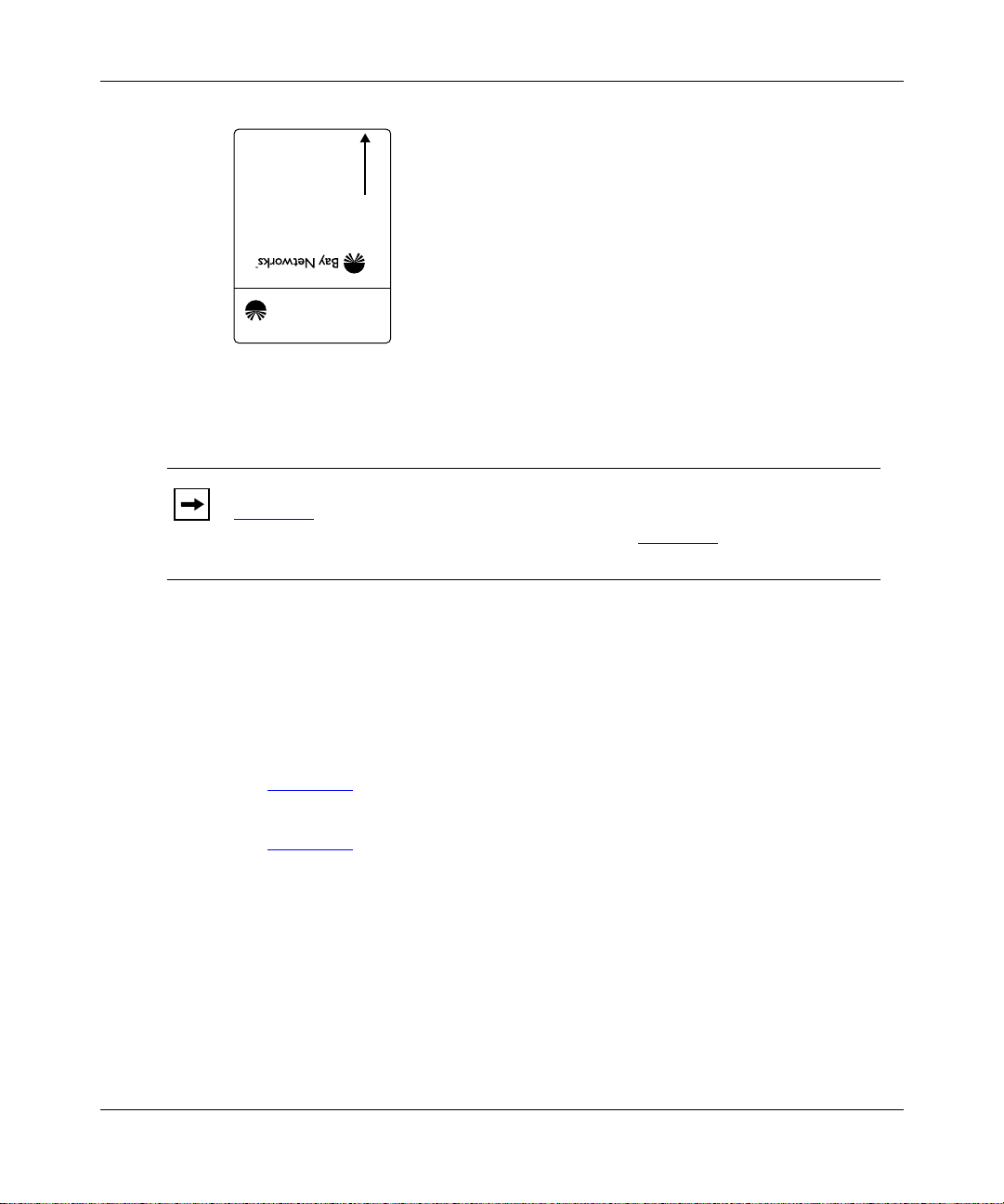
Installing and Operating BayStack AN and ANH Routers
INSERT
AN0060A
Figure 3-1. Flash Memory Card
Note:
If you installed a memory card prote ct or in your AN (as descr ibed in
Chapter 1), you should have installed your flash memory card at that time. If
you did not ins tall th e flash m emory card, refer to Chapter 1 for instructions on
removing the AN enclosure so that you can install the memory card.
3-6
Before starting the AN/ANH, install the flash memory card supplied with the
router by following these steps:
Position the card w ith the label facing up and the I N SE RT arrow
1.
pointing toward the card receptacle.
Insert the card into the receptacle.
2.
Figure 3-2
shows ho w to insert the flash memory card in an AN that does not
have a flash memory card protector installed.
Figure 3-3
Gently push the card until it f its snugly into place.
3.
shows how to insert the flash memory card in an ANH.
114113-B Rev. 00
Page 93

Starting the AN and ANH
If the card is new, and you did not obtain it from Bay Networks, you must format
the card before attempting to wr ite to it. You can format the card using Site
Manager software or the
format
command avai lable with the Bay Networks
Technician Interface. (Refer to Using Technician Interface Software for
instructions.)
Caution:
If you attempt to boot the AN/ANH without the flash memory card
inserted, the router will not operate.
Access Node
RUN
POWER
Figure 3-2. Inserting a Flash Memory Card in the AN or 12-Port ANH
BOOT
DIAG
Card Receptacle
AN0015A
114113-B Rev. 00
5
678
Partition
12345678
Link
Access Node Hub
AN0061A
Figure 3-3. Inserting a Flash Memory Card in the 8-Port ANH Card
Receptacle
3-7
Page 94

Installing and Operating BayStack AN and ANH Routers
Using EZ-Install
To use EZ-Install:
Install the AN or ANH and attached communications equipment as
1.
described in Chapter 1 (AN and 12-port ANH) or Chapter 2 (8-por t
ANH).
There must be at least one synchronous or Ethernet connection to a remote
BootP server.
Although you do not need a modem or c onsole conne ction f or EZ-Install , Bay
Networks strongly recommends that you connect a modem or console to the
AN or ANH so that y ou can issue commands to the router and view messages.
Contact your network administrator to verify that the remote network is
2.
set up so that you can start the EZ-Install procedure.
Make sure the flash mem or y car d is in sta lled , a s des cri be d in “Installing
3.
the Flash Memory Card,” earlier in this chapter.
Press the power switch on the AN/ANH back panel to the On position.
4.
3-8
If you turn on the AN/ANH be for e the ne tw ork admini stra tor is ready or
Note:
without a memory card installed, EZ- Install will fail. Restart the router as
described in Chapter 4.
After you turn on the AN/ANH, it begins diagnostic tests. Your console
displays the message
*****Testing Memory** ***
with the amount of
memory available.
After it passes the diagnostic tests, the AN/ANH activ ates and completes
EZ-Install. (The AN/ANH obtains a software image from the local file
system, its IP address from the upstream router, and a configuration file from
the BootP server.) The AN/ANH then starts bridging an d routi ng traffic.
When you boot the AN/ANH, its LEDs flash in a parti cular orde r. To interpret
the LED sequence a nd tr oubleshoot any pote ntial problems , refer toChapter 4,
“Operating the AN and ANH.”
114113-B Rev. 00
Page 95

Starting the AN and ANH
Using Netboot, Directed Netboot, or Local Boot
To netboot or loc al-boot the AN/ANH, you use a command interface to the router
software ca lled t he Dia gnostic Monitor. (You can also use the Technician Interface
or Site Manager for the Directed Netboot procedure.)
The AN/ANH ships with its configuration sour ce set to network and its image
source set to local. Using the Diagnostic Monitor, you change the default
configura tion, bypassing the EZ-Inst al l procedure. The Diagnostic Monitor
bconfig
boot image.
Logging In to the Diagnostic Monitor
You begin the Netboot, Directed Netboot, or Local Boot proce ss by logging in to
the Diagnostic Monitor. Complete the following steps:
1.
command enables you to specify the source for the configuration file and
Install the AN or ANH and attached communications equipment as
described in Chapter 1 (AN) or Chapter 2 (8-port AN H).
Turn on the local management console.
2.
For instruct ions on connecting a management console, see Chapter 1
12-port ANH) or Chapter 2 (8-port ANH).
Make sure the flash memory card is installed as described in “Installing
3.
the Flash Memory Card,” earlier in this chapter.
Press the power switch on the AN/ANH back panel to the On position.
4.
After you turn the router on, your console displays the message
*****T es tin g Me mory** ** *
with the amount of memory available.
Next, diagnostic software (AN Diagnostics) begins to test the router. The
console displays:
• Diagnostic software version
• Information about the AN or ANH hardware (model, revision, and serial
numbers)
• Size of flash memory and dynamic random access memory (DRAM)
• Results of diagnostic tests as each test c ompletes
Figure 3-4
shows sample output from diagno stic tests.
(AN or
114113-B Rev. 00
3-9
Page 96

Installing and Operating BayStack AN and ANH Routers
AN Diagnostics: Version - 7.xx - Wed Aug 30 16:29:38 EDT 1996
MOD ID = 0x41A (1050) Rev = 0x00 (00) S/N = 0xxxxxxxxx
Flash Card instal Memory = xMB
TYPE "?" or "h" for HELP
Test Description Status
TEST 001 SNPROM Checksum Test -------------------- PASSED
TEST 002 DIAG PROM Checksum Test ----------------- PASSED
TEST 003 OS PROM Checksum Test ------------------- PASSED
TEST 004 Memory Alignment Test ------------------- PASSED
TEST 005 Control Register 0 Test ----------------- PASSED
TEST 006 Control Register 1 Test ----------------- PASSED
TEST 007 Control Register 2 Test ----------------- PASSED
TEST 008 Control Register 5 Test ----------------- PASSED
TEST 009 Sts Registers Test ---------------------- PASSED
TEST 00A EEPROM Test (5 msec per byte write)------ BYPASS
TEST 00B Novram Battery Check -------------------- PASSED
.
.
.
Figure 3-4. Running AN Diagnostics
AN0062A
3-10
Befor e diagnostics are complete, press Control-c to bypass the automatic
5.
boot process.
Note:
Be sure to press Control-c before the diagnostic tests complete. To
display the AN Diagnostics login prompt, you must interrupt the power-up
sequence before the AN/ANH boots.
The AN Diagnostics login prompt appears (Figure 3-5)
.
114113-B Rev. 00
Page 97

Starting the AN and ANH
TEST 00E Sync Port2 Int Loop TX Chain Test ------- PASSED
TEST 00F Sync Port2 Int Loop RX Chain Test -------
AN Diagnostics: Version - 6.01 - Mon July 24 07:54:00 EDT 1996
Login: Manager
AN Diagnostics: Version - 6.01 - Mon July 24 07:54:00 EDT 1996
MOD ID = 0x40D (1037) Rev = 01 S/N = 015693
Flash = 4MB Memory = 4MB
AN_DIAG>>
Figure 3 -5 . Lo ggi ng In to th e D iagnostic Mo ni t or
Enter the following command at the login prompt:
6.
Manager
You must type
Manager
with an uppercase “M.”
The Diagnostic Monitor command-l ine prompt (AN_DIAG) appears
(Figure 3-5)
. You are now using the Diagnostic Monitor.
Control-c
invoked
AN00063A
114113-B Rev. 00
To use the Netboot, Directed Netboot, or Local Boot option, refer to the
7.
specific section that describes the procedure you want to use.
• Continuing with Netboot
• Continuing with Directed Netboot
• Continuing with Local Boot
3-11
Page 98

Installing and Operating BayStack AN and ANH Routers
Continuing with Netboot
To use Netboot:
Contact your network administrator to verify that the network is set up
1.
for the Netboot procedure.
Ask your network administrator (or refer toAppendix A, “Configuring
2.
the AN or ANH for Netboot and Directed Netboot”) for the interfa ce
configu ration command to use in step 3. Write the command in
Figure 3-6
for reference.
The
ifconfig
command configures the IP address f or the connection you will
use for Netboot.
Figure 3-6. Your ifconfig Command
Enter the appropriate command at the Diagnostic Monitor prompt to
3.
configure the router’s interface to the network.
Figure 3-7
AN_DIAG>> ifconfig xcvr1 192.32.37.125 255.255.255.224
AN_DIAG>>
Figure 3-7. Sample Interface Configuration Command
shows a sample command.
AN00017A
3-12
Enter the following command to verify the configuration you specified in
4.
step 3:
getcfg
As Figure 3-8 shows, the
getcfg
command displays the locatio n of the boot
image and the network configuration file, a s well as the interface
configuration you specified using the
ifconfig
command.
114113-B Rev. 00
Page 99

Starting the AN and ANH
AN_DIAG>> getcfg
Boot Options:
boot image=local
boot config=network
Verify
NetBoot Parameters:
XCVR1...IP=192.32.37.125, Mask=255.255.255.224
COM1....EZ-Install
COM2....EZ-Install
XCVR2...None
AN_DIAG>>
Figure 3-8. Verifying the Interface Configuration
Note:
The location of the image and configuration files is either local or
network. Local means that the required file (an.exe or config) is stored on the
router’ s loc al f ile system ( flash memory c ard). Network means the r equir ed fi le
is stored on a workstation loc ated across the network.
If the configu ration i nf ormation is corr ect, go t o the next step. Otherwise,
5.
reenter the correct
ifconfig
command. Contact your network
administrator if you need assistance.
Type the following command and press the Return key to run the
6.
diagnostic tests and boot the AN:
AN0065A
114113-B Rev. 00
reset
Or, type
boot
and press the Return key to boot the AN/ANH without running
the diagnostic test s.
3-13
Page 100

Installing and Operating BayStack AN and ANH Routers
Figure 3-9 shows sample output from a
AN_DIAG>> boot
Booting Access Node...
Starting OS Kernel for network boot...
Attempting Netboot on XCVR1
Attempting EZ-Install on COM1, using Wellfleet Pt-to-Pt
Attempting EZ-Install on COM2, using Wellfleet Pt-to-Pt
IP interface active on XCVR1, attempting BOOTP
Received BOOTP response from server 192.32.3.9 on XCVR1
Retrieving config 'config' from network. done
Found image '1:an.exe' on local file system...booting
Image is in compressed format... decompressing
Bay Networks, Inc. and its Licensors.
Copyright 1992, 1993, 1994, 1995, 1996, 1997, 1998.
All rights reserved.
Login:
Figure 3-9. AN/ANH Netboot
boot
command.
AN0018A
3-14
Note:
If the AN/ANH tries to netboot and cannot find a software image or
configura tion file, it attempts to local-boot once. If both attempts fail, the AN
Diagnostic Monitor login prompt (
AN_DIAG>>
) appears on the AN console. In
this case, you or your network admin istrator must troubleshoot the problem.
When you boot the AN/ANH, its LEDs flash in a particular order. To interpret the
LED sequence and troubleshoot an y pote ntial problems, refer to Chapter 4,
“Operating the AN and ANH.”
After connecting the AN/ANH to the network, you can replace the local console
with a modem connection to enable remote dial-in access. For instruct ions on
connecting a modem, see Chapter 1
(AN or 12-port ANH) or Chapter 2 (8-port
ANH).
114113-B Rev. 00
 Loading...