

Page 1

Avaya 1600 Series IP Deskphones
Administrator Guide
Release 1.3.x
16-601443
Issue 4
April 2010
Page 2

© 2010 Avaya Inc.
All Rights Reserved.
Notice
While reasonable efforts were made to ensure that the information in this
document was complete and accurate at the time of printing, Avaya Inc. can
assume no liability for any errors. Changes and corrections to the information
in this document may be incorporated in future releases.
For full legal page information, please see the complete document, Avaya
Legal Page for Hardware Documentation, Document number 03-600759.
To locate this document on our Web site, simply go to
http://www.avaya.com/support
the search box.
Documentation disclaimer
Avaya Inc. is not responsible for any modifications, additions, or deletions to
the original published version of this documentation unless such modifications,
additions, or deletions were performed by Avaya. Customer and/or End User
agree to indemnify and hold harmless Avaya, Avaya's agents, servants and
employees against all claims, lawsuits, demands and judgments arising out of,
or in connection with, subsequent modifications, additions or deletions to this
documentation to the extent made by the Customer or End User.
Link disclaimer
Avaya Inc. is not responsible for the contents or reliability of any linked Web
sites referenced elsewhere within this documentation, and Avaya does not
necessarily endorse the products, services, or information described or offered
within them. We cannot guarantee that these links will work all of the time and
we have no control over the availability of the linked pages.
Warr ant y
Avaya Inc. provides a limited warranty on this product. Refer to your sales
agreement to establish the terms of the limited warranty. In addition, Avaya’s
standard warranty language, as well as information regarding support for this
product, while under warranty, is available through the following Web site:
http://www.avaya.com/support
Copyright
Except where expressly stated otherwise, the Product is protected by copyright
and other laws respecting proprietary rights. Unauthorized reproduction,
transfer, and or use can be a criminal, as well as a civil, offense under the
applicable law.
Avaya support
Avaya provides a telephone number for you to use to report problems or to ask
questions about your product. The support telephone number
is 1-800-242-2121 in the United States. For additional support telephone
numbers, see the Avaya Web site:
http://www.avaya.com/support
Software License
USE OR INSTALLATION OF THE PRODUCT INDICATES THE END USER’S
ACCEPTANCE OF THE TERMS SET FORTH HEREIN AND THE GENERAL
LI CE N SE TE RMS AVAI LAB LE ON THE AVAYA W EB S IT E AT
http://support.avaya.com/LicenseInfo/
YOU DO NOT WISH TO BE BOUND BY THESE TERMS, YOU MUST
RETURN THE PRODUCT(S) TO THE POINT OF PURCHASE WITHIN TEN
(10) DAYS OF DELIVERY FOR A REFUND OR CREDIT.
Avaya grants End User a license within the scope of the license types
described below. The applicable number of licenses and units of capacity for
which the license is granted will be one (1), unless a different number of
licenses or units of capacity is specified in the Documentation or other
materials available to End User. “Designated Processor” means a single
stand-alone computing device. “Server” means a Designated Processor that
hosts a software application to be accessed by multiple users. “Software”
means the computer programs in object code, originally licensed by Avaya and
ultimately utilized by End User, whether as stand-alone Products or
pre-installed on Hardware. “Hardware” means the standard hardware
Products, originally sold by Avaya and ultimately utilized by End User.
License Type(s):
Designated System(s) License (DS). End User may install and use each copy
of the Software on only one Designated Processor, unless a different number
of Designated Processors is indicated in the Documentation or other materials
available to End User. Avaya may require the Designated Processor(s) to be
identified by type, serial number, feature key, location or other specific
designation, or to be provided by End User to Avaya through electronic means
established by Avaya specifically for this purpose.
and search for the document number in
(“GENERAL LICENSE TERMS”). IF
Third-party Components
Certain software programs or portions thereof included in the Product may
contain software distributed under third party agreements (“Third Party
Components”), which may contain terms that expand or limit rights to use
certain portions of the Product (“Third Party Terms”). Information identifying
Third Party Components and the Third Party Terms that apply to them is
available on Avaya’s Web site at:
http://support.avaya.com/ThirdPartyLicense/
Interference
Using a cell, mobile, or GSM telephone, or a two-way radio in close proximity to
an Avaya IP Telephone might cause interference.
Security
See http://support.avaya.com/security
vulnerabilities in Avaya products. See http://support.avaya.com
latest software patches and upgrades. For information about secure
configuration of equipment and mitigation of toll fraud threats, see the Avaya
Toll Fraud and Security Handbook at http://support.avaya.com
to locate and/or report known
to locate the
.
Page 3

Contents
Chapter 1: Introduction . . . . . . . . . . . . . . . . . . . . . . . . . . . 7
About This Guide . . . . . . . . . . . . . . . . . . . . . . . . . . . . . . . . . . . 7
Document Organization . . . . . . . . . . . . . . . . . . . . . . . . . . . . . . . . 8
Other Documentation . . . . . . . . . . . . . . . . . . . . . . . . . . . . . . . . . 9
Chapter 2: Administration Overview and Requirements . . . . . . . . . 11
1600 Series IP Telephones . . . . . . . . . . . . . . . . . . . . . . . . . . . . . . 11
Parameter Data Precedence . . . . . . . . . . . . . . . . . . . . . . . . . . . . . 15
The Administrative Process. . . . . . . . . . . . . . . . . . . . . . . . . . . . . . 15
Administrative Checklist . . . . . . . . . . . . . . . . . . . . . . . . . . . . . 16
Telephone Initialization Process . . . . . . . . . . . . . . . . . . . . . . . . . . . 17
Step 1: Telephone to Network . . . . . . . . . . . . . . . . . . . . . . . . . . 17
Step 2: DHCP Server to Telephone . . . . . . . . . . . . . . . . . . . . . . . . 18
Step 3: Telephone and File Server . . . . . . . . . . . . . . . . . . . . . . . . 18
Step 4: Telephone and the Call Server . . . . . . . . . . . . . . . . . . . . . . 18
Error Conditions . . . . . . . . . . . . . . . . . . . . . . . . . . . . . . . . . . . . 19
Chapter 3: Network Requirements . . . . . . . . . . . . . . . . . . . . . 21
Network Assessment . . . . . . . . . . . . . . . . . . . . . . . . . . . . . . . . . 21
Hardware Requirements. . . . . . . . . . . . . . . . . . . . . . . . . . . . . . . . 21
Server Requirements . . . . . . . . . . . . . . . . . . . . . . . . . . . . . . . . . 22
DHCP Server . . . . . . . . . . . . . . . . . . . . . . . . . . . . . . . . . . . . 22
HTTP/HTTPS Server . . . . . . . . . . . . . . . . . . . . . . . . . . . . . . . . 22
Required Network Information . . . . . . . . . . . . . . . . . . . . . . . . . . . . 23
Other Network Considerations . . . . . . . . . . . . . . . . . . . . . . . . . . . . 24
SNMP . . . . . . . . . . . . . . . . . . . . . . . . . . . . . . . . . . . . . . . . 24
Reliability and Performance. . . . . . . . . . . . . . . . . . . . . . . . . . . . 25
QoS . . . . . . . . . . . . . . . . . . . . . . . . . . . . . . . . . . . . . . . . . 25
IEEE 802.1P and 802.1Q . . . . . . . . . . . . . . . . . . . . . . . . . . . . . . 25
Network Audio Quality Display on 1600 Series IP Telephones . . . . . . . . . 26
IP Address Lists and Station Number Portability . . . . . . . . . . . . . . . . 26
TCP/UDP Port Utilization . . . . . . . . . . . . . . . . . . . . . . . . . . . . . 27
Security. . . . . . . . . . . . . . . . . . . . . . . . . . . . . . . . . . . . . . . 30
Registration and Authentication . . . . . . . . . . . . . . . . . . . . . . . 30
Issue 5 April 2010 3
Page 4

Contents
Chapter 4: Avaya Aura Communication Manager Administration . . . . 31
Call Server Requirements . . . . . . . . . . . . . . . . . . . . . . . . . . . . . . . 31
Switch Compatibility and Aliasing IP Telephones. . . . . . . . . . . . . . . . 31
Media Server (Switch) Administration . . . . . . . . . . . . . . . . . . . . . . . . 33
IP Interface and Addresses . . . . . . . . . . . . . . . . . . . . . . . . . . . . 33
UDP Port Selection . . . . . . . . . . . . . . . . . . . . . . . . . . . . . . . . 34
RSVP and RTCP . . . . . . . . . . . . . . . . . . . . . . . . . . . . . . . . . . 34
QoS . . . . . . . . . . . . . . . . . . . . . . . . . . . . . . . . . . . . . . . . . 34
IEEE 802.1P and 802.1Q . . . . . . . . . . . . . . . . . . . . . . . . . . . . . . 34
NAT . . . . . . . . . . . . . . . . . . . . . . . . . . . . . . . . . . . . . . . . . 35
DIFFSERV . . . . . . . . . . . . . . . . . . . . . . . . . . . . . . . . . . . . . 35
Voice Mail Integration . . . . . . . . . . . . . . . . . . . . . . . . . . . . . . . . . 36
1600 Series IP Telephones with Avaya Aura Communication Manager 5.2
Native Support . . . . . . . . . . . . . . . . . . . . . . . . . . . . . . . . . . 36
1600 Series IP Telephones Aliased as 4600 Series IP Telephones. . . . . . . 36
Telephone Administration. . . . . . . . . . . . . . . . . . . . . . . . . . . . . . . 37
System-Wide Administration . . . . . . . . . . . . . . . . . . . . . . . . . . . 37
Feature-Related System Parameters . . . . . . . . . . . . . . . . . . . . . . . 37
Administering Stations . . . . . . . . . . . . . . . . . . . . . . . . . . . . . . . . 38
Aliasing 1600 Series IP Telephones . . . . . . . . . . . . . . . . . . . . . . . 39
Administering Features . . . . . . . . . . . . . . . . . . . . . . . . . . . . . . 39
Feature Buttons and Call Appearances . . . . . . . . . . . . . . . . . . . . . . . 40
For the 1603/1603SW/1603-I/1603SW-I and 1608/1608-I IP Telephones . . . . 40
For the 1616/1616-I IP Telephones . . . . . . . . . . . . . . . . . . . . . . . . 40
Conference Details Screen for Ad-Hoc Conferences . . . . . . . . . . . . . . 41
Shuffling . . . . . . . . . . . . . . . . . . . . . . . . . . . . . . . . . . . . . . . . 41
Printing Button Labels . . . . . . . . . . . . . . . . . . . . . . . . . . . . . . . . 42
Chapter 5: Server Administration . . . . . . . . . . . . . . . . . . . . . 43
Software Checklist. . . . . . . . . . . . . . . . . . . . . . . . . . . . . . . . . . . 43
DHCP and File Servers . . . . . . . . . . . . . . . . . . . . . . . . . . . . . . . . 43
DHCP Server Administration . . . . . . . . . . . . . . . . . . . . . . . . . . . . . 44
DHCP Generic Setup . . . . . . . . . . . . . . . . . . . . . . . . . . . . . . . 44
Windows NT 4.0 DHCP Server . . . . . . . . . . . . . . . . . . . . . . . . . . 48
Verifying the Installation of the DHCP Server . . . . . . . . . . . . . . . . 48
Creating a DHCP Scope for the IP Telephones . . . . . . . . . . . . . . . 49
Editing Custom Options . . . . . . . . . . . . . . . . . . . . . . . . . . . . 50
Adding the DHCP Option . . . . . . . . . . . . . . . . . . . . . . . . . . . 50
Activating the Leases . . . . . . . . . . . . . . . . . . . . . . . . . . . . . 51
4 Avaya 1600 Series IP Deskphones Administrator Guide
Page 5

Verifying Your Configuration . . . . . . . . . . . . . . . . . . . . . . . . . 51
Windows 2000 DHCP Server . . . . . . . . . . . . . . . . . . . . . . . . . . . 52
Verifying the Installation of the DHCP Server . . . . . . . . . . . . . . . . 52
Adding DHCP Options . . . . . . . . . . . . . . . . . . . . . . . . . . . . . 54
Activating the New Scope . . . . . . . . . . . . . . . . . . . . . . . . . . . 55
HTTP Generic Setup . . . . . . . . . . . . . . . . . . . . . . . . . . . . . . . . . . 55
HTTP Configuration for Backup/Restore. . . . . . . . . . . . . . . . . . . . . . . 56
For IIS Web Servers . . . . . . . . . . . . . . . . . . . . . . . . . . . . . . . . 56
Web Configuration Tool . . . . . . . . . . . . . . . . . . . . . . . . . . . . . . . . 58
Chapter 6: Telephone Software and Application Files . . . . . . . . . . 61
General Download Process . . . . . . . . . . . . . . . . . . . . . . . . . . . . . . 61
Software . . . . . . . . . . . . . . . . . . . . . . . . . . . . . . . . . . . . . . . . 61
1600 Series IP Telephone Scripts and Application Files . . . . . . . . . . . . . . 62
Choosing the Right Application File and Upgrade Script File . . . . . . . . . 62
Upgrade Script File . . . . . . . . . . . . . . . . . . . . . . . . . . . . . . . . 62
Settings File . . . . . . . . . . . . . . . . . . . . . . . . . . . . . . . . . . . . 63
Contents of the Settings File . . . . . . . . . . . . . . . . . . . . . . . . . . . 64
Contents
The GROUP System Value . . . . . . . . . . . . . . . . . . . . . . . . . . . . . . 65
Chapter 7: Administering Telephone Options . . . . . . . . . . . . . . . 67
Administering Options for the 1600 Series IP Telephones . . . . . . . . . . . . . 67
VLAN Considerations . . . . . . . . . . . . . . . . . . . . . . . . . . . . . . . . . 73
VLAN Tagging . . . . . . . . . . . . . . . . . . . . . . . . . . . . . . . . . . . 73
VLAN Default Value and Priority Tagging . . . . . . . . . . . . . . . . . . . . 74
VLAN Separation. . . . . . . . . . . . . . . . . . . . . . . . . . . . . . . . . . 75
DNS Addressing . . . . . . . . . . . . . . . . . . . . . . . . . . . . . . . . . . . . 76
IEEE 802.1X . . . . . . . . . . . . . . . . . . . . . . . . . . . . . . . . . . . . . . 77
802.1X Pass-Through and Proxy Logoff . . . . . . . . . . . . . . . . . . . . . 78
802.1X Supplicant Operation . . . . . . . . . . . . . . . . . . . . . . . . . . . 78
Link Layer Discovery Protocol (LLDP) . . . . . . . . . . . . . . . . . . . . . . . . 79
Local Administrative Options Using the Telephone Dialpad . . . . . . . . . . . . 84
Clear Procedure . . . . . . . . . . . . . . . . . . . . . . . . . . . . . . . . . . 84
Disable/Enable Debug Mode . . . . . . . . . . . . . . . . . . . . . . . . . . . 85
Group Identifier . . . . . . . . . . . . . . . . . . . . . . . . . . . . . . . . . . 86
Reset System Values . . . . . . . . . . . . . . . . . . . . . . . . . . . . . . . 87
Restart the Telephone . . . . . . . . . . . . . . . . . . . . . . . . . . . . . . . 88
Issue 5 April 2010 5
Page 6

Contents
Interface Control . . . . . . . . . . . . . . . . . . . . . . . . . . . . . . . . . . . . 89
The View Administrative Option . . . . . . . . . . . . . . . . . . . . . . . . . 91
Static Addressing Installation . . . . . . . . . . . . . . . . . . . . . . . . . . 94
Disable/Enable Event Logging . . . . . . . . . . . . . . . . . . . . . . . . . . 97
Logoff. . . . . . . . . . . . . . . . . . . . . . . . . . . . . . . . . . . . . . . . 98
Self-Test Procedure . . . . . . . . . . . . . . . . . . . . . . . . . . . . . . . . 99
Language Selection . . . . . . . . . . . . . . . . . . . . . . . . . . . . . . . . . . 100
1600 Series Global Telephones . . . . . . . . . . . . . . . . . . . . . . . . . . 100
1600 Series International Telephones . . . . . . . . . . . . . . . . . . . . . . 102
Enhanced Local Dialing . . . . . . . . . . . . . . . . . . . . . . . . . . . . . . . . 105
Backup/Restore . . . . . . . . . . . . . . . . . . . . . . . . . . . . . . . . . . . . 106
Backup . . . . . . . . . . . . . . . . . . . . . . . . . . . . . . . . . . . . . . . 107
Restore . . . . . . . . . . . . . . . . . . . . . . . . . . . . . . . . . . . . . . . 108
Chapter 8: Administering Applications and Options . . . . . . . . . . . 111
Customizing 1600 Series IP Telephone Applications and Options. . . . . . . . . 111
The Application Status Flag (APPSTAT) . . . . . . . . . . . . . . . . . . . . . 114
Appendix A: Glossary of Terms . . . . . . . . . . . . . . . . . . . . . . 117
Appendix B: Related Documentation . . . . . . . . . . . . . . . . . . . 119
IETF Documents . . . . . . . . . . . . . . . . . . . . . . . . . . . . . . . . . . 119
ITU Documents. . . . . . . . . . . . . . . . . . . . . . . . . . . . . . . . . . . 120
ISO/IEC, ANSI/IEEE Documents . . . . . . . . . . . . . . . . . . . . . . . . . 121
Appendix C: Sample Administration Forms . . . . . . . . . . . . . . . . 123
Index . . . . . . . . . . . . . . . . . . . . . . . . . . . . . . . . . . 133
6 Avaya 1600 Series IP Deskphones Administrator Guide
Page 7

Chapter 1: Introduction
About This Guide
This guide is for personnel who administer Avaya Aura™ Communication Manager, Avaya Aura
Communication Manager Branch (formerly known as Avaya Distributed Office), DHCP, HTTP/
HTTPS servers for Avaya 1600 Series IP Deskphones, a Local Area Network (LAN), or a Web
server.
The 1600 Series IP Telephones use Internet Protocol (IP) technology with Ethernet line
interfaces and support the H.323 protocol only. The 1600 Series IP Telephones provide support
for DHCP, HTTP, and HTTPS over IPv4/UDP, which enhance the administration and servicing of
the telephones. These telephones use DHCP to obtain dynamic IP Addresses, and HTTPS or
HTTP to download new versions of software or customized settings for the telephones.
!
CAUTION:
CAUTION: Avaya does not support many of the products mentioned in this document. Take
care to ensure that there is adequate technical support available for servers used
with any 1600 Series IP Telephone system. If the servers are not functioning
correctly, the 1600 Series IP Telephones might not operate correctly.
Issue 5 April 2010 7
Page 8

Introduction
Document Organization
The guide contains the following sections:
Chapter 1:
Chapter 2: Administration
Overview and Requirements
Chapter 3:
Requirements
Chapter 4: Avaya Aura
Communication Manager
Administration
Chapter 5:
Administration
Chapter 6: Telephone
Software and Application Files
Chapter 7:
Telephone Options
Chapter 8: Administering
Applications and Options
Appendix A: Glossary of
Te rms
Appendix B: Related
Documentation
Appendix C:
Administration Forms
Introduction Provides an overview of this document.
Network
Server
Administering
Sample
Provides an overview of the administrative process and
describes general hardware, software, and operational
requirements.
Describes administrative requirements for your Local Area
Network.
Describes how to administer Avaya Aura Communication
Manager to operate with 1600 Series IP Telephones.
Describes DHCP, HTTP, and HTTPS administration for the
1600 Series IP Telephones.
Describes telephone software, covers application software
downloads, and provides information about the configuration
file.
Describes how to use file parameters and options to
administer 1600 Series IP Telephones. Covers backup and
restoration of telephone data. Also describes how to use local
procedures to customize a single telephone from the dialpad.
Provides a table of customizable application-specific
parameters, to provide administrative control of telephone
functions and options.
Provides a glossary of terms used in this document or which
can be applicable to 1600 Series IP Telephones.
Provides references to external documents that relate to
telephony in general, which can provide additional
information about specific aspects of the telephones.
Provides examples of Avaya Aura Communication Manager
forms related to system-wide and individual telephone
administration.
8 Avaya 1600 Series IP Deskphones Administrator Guide
Page 9

Other Documentation
See the Avaya support site at http://www.avaya.com/support for 1600 Series IP Telephone
technical and end user documentation.
The following documents are available for the 1600 Series IP Telephones:
● Avaya 1600 Series IP Deskphones Installation and Maintenance Guide, Document
Number 16-601438.
● Avaya one-X™ Deskphone Value Edition 1600 Series IP Telephone Pre-Installation
Checklist, Document Number 16-601439.
● Avaya one-X™ Deskphone Value Edition 1600 Series IP Telephone Safety Instructions,
Document Number 16-601440.
● Avaya one-X™ Deskphone Value Edition 1600 Series IP Telephones BM32 Button
Module Installation and Safety Instructions, Document Number 16-601441.
● Avaya one-X™ 9600 Series IP Telephone Application Programmer Interface (API) Guide,
Document Number 16-601442.
Other Documentation
● Avaya 1600 Series IP Deskphones Administrator Guide, Document Number 16-601443.
● Avaya 1603/1603SW/1603-I/1603SW-I IP Deskphone User Guide, Document Number
16-601444.
● Avaya 1608/1608-I IP Deskphone User Guide, Document Number 16-601446.
● Avaya 1616/1616-I IP Deskphone User Guide, Document Number 16-601448.
● Avaya one-X™ Deskphone Value Edition 1600 Series IP Telephones BM32 Button
Module User Guide, Document Number 16-601450
● Avaya one-X™ Deskphone Value Edition 1600 Series IP Telephone Wall Mount
Instructions, Document Number 16-601453.
● Avaya one-X™ Deskphone Value Edition 1600 Series IP Telephone Stand Instructions,
Document Number 16-601451.
● Avaya 1603/1603SW/1603-I/1603SW-I IP Deskphone Quick Reference,
Document Number 16-601445.
● Avaya 1608/1608-I IP Deskphone Quick Reference, Document Number 16-601447.
● Avaya 616/1616-I IP Deskphone Quick Reference, Document Number 16-601449.
See Appendix B: Related Documentation
for a list of non-Avaya documents, such as those
published by the Internet Engineering Task Force (IETF) and the International
Telecommunication Union (ITU).
Issue 5 April 2010 9
Page 10

Introduction
10 Avaya 1600 Series IP Deskphones Administrator Guide
Page 11

Chapter 2: Administration Overview and
Requirements
1600 Series IP Telephones
The 1600 Series IP Telephones currently support the H.323 signaling protocol.
The H.323 standard provides for real time audio, video, and data communications transmission
over a packet network. An H.323 telephone protocol stack comprises several protocols:
● H.225 for registration, admission, status (RAS), and call signaling,
● H.245 for control signaling,
● Real Time Transfer Protocol (RTP), and
● Real Time Control Protocol (RTCP)
The parameters under which the 1600 Series IP Telephones need to operate are summarized
as follows:
● Telephone and System Administration on the Avaya Media Server, as covered in
Chapter 4:
Avaya Aura Communication Manager Administration.
● IP address management for the telephone, as covered in DHCP and File Servers on
page 43 for dynamic addressing. For static addressing, see the Avaya 1600 Series IP
Deskphones Installation and Maintenance Guide.
● Tagging Control and VLAN administration for the telephone, if appropriate, as covered in
Chapter 7:
● Quality of Service (QoS) administration for the telephone, if appropriate. QoS is covered in
QoS
● Interface administration for the telephone, as appropriate. Administer the telephone to
LAN interface using the PHY1 parameter described in Chapter 3:
Administering Telephone Options.
on page 25 and QoS on page 34.
Network Requirements.
Administer the telephone to PC interface using the PHY2 parameter described in “Local
Procedures” in the Avaya 1600 Series IP Deskphones Installation and Maintenance
Guide.
● Application-specific telephone administration, if appropriate, as described in Chapter
8: Administering Applications and Options. An example of application-specific data is
specifying the extent to which users can add/edit/delete data for Contacts entries.
● Protocol administration, for example, Simple Network Management Protocol (SNMP) and
Link Layer Discovery Protocol (LLDP).
Issue 5 April 2010 11
Page 12

Administration Overview and Requirements
Table 1 indicates that you can administer system parameters in a variety of ways and use a
variety of delivery mechanisms like:
● Maintaining the information on the call server.
● Manually entering the information by means of the telephone dialpad.
● Administering the DHCP server.
● Editing the configuration file on the applicable HTTP or HTTPS file server.
● User modification of certain parameters, when given administrative permission to do so.
Note:
Note: Not all parameters can be administered on all delivery mechanisms.
Table 1: Administration Alternatives and Options for 1600 Series IP
Telephones
Administrative
Parameter(s)
Mechanisms
For More Information See:
Telephone
Avaya call server Chapter 4:
Administration
IP Addresses DHCP
(strongly
recommended)
Configuration file Chapter 6: Telephone Software and Application
Manual administration
at the telephone
LLDP Link Layer Discovery Protocol (LLDP) on page 79.
Tagging and
LLDP
VLAN
DHCP DHCP Server Administration
Configuration file
(strongly
recommended)
Avaya Aura Communication Manager
Administration, Chapter 5: Server Administration,
and Appendix B: Related Documentation.
DHCP and File Servers on page 43, and especially
DHCP Server Administration
on page 44.
Files and Chapter 7: Administering Telephone
Options.
“Static Addressing Installation” in the Avaya 1600
Series IP Deskphones Installation and
Maintenance Guide.
Link Layer Discovery Protocol (LLDP) on page 79.
on page 44, and
Chapter 7:
DHCP and File Servers
Administering Telephone Options.
on page 43 and Chapter
7: Administering Telephone Options.
12 Avaya 1600 Series IP Deskphones Administrator Guide
1 of 3
Page 13

Table 1: Administration Alternatives and Options for 1600 Series IP
Telephones (continued)
Administrative
Parameter(s)
Mechanisms
For More Information See:
1600 Series IP Telephones
Manual administration
at the telephone
“Static Addressing Installation” in the Avaya 1600
Series IP Deskphones Installation and
Maintenance Guide.
Avaya call server Use the change ip-network-map command to
configure the VLAN ID.
2 of 3
Issue 5 April 2010 13
Page 14

Administration Overview and Requirements
Table 1: Administration Alternatives and Options for 1600 Series IP
Telephones (continued)
Administrative
Parameter(s)
Mechanisms
For More Information See:
Quality of
Service
Avaya call server
(strongly
UDP Port Selection on page 34 and
Appendix B: Related Documentation
recommended)
DHCP DHCP and File Servers on page 43, and Chapter
7: Administering Telephone Options.
Configuration file DHCP and File Servers on page 43, and Chapter
7: Administering Telephone Options.
Interface DHCP DHCP and File Servers
6: Telephone Software and Application Files.
Configuration file
(strongly
DHCP and File Servers
6: Telephone Software and Application Files.
recommended)
Manual administration
at the telephone
“Ethernet (Hub) Interface Enable/Disable” in the
Avaya 1600 Series IP Deskphones Installation and
Maintenance Guide.
Link Layer Discovery Protocol (LLDP) on page 79.
DHCP Server Administration on page 44.
Also, Chapter 8:
Administering Applications and
Application specific
parameters
LLDP
DHCP DHCP and File Servers on page 43, and especially
Options.
.
on page 43, and Chapter
on page 43, and Chapter
Configuration file
(strongly
recommended)
DHCP and File Servers on page 43, and especially
HTTP Generic Setup on page 55. Also,
Chapter 8:
General information about administering DHCP servers is covered in DHCP and File
Servers on page 43, and more specifically, DHCP Server Administration on page 44. General
information about administering HTTP servers is covered in DHCP and File Servers
specifically, HTTP Generic Setup
telephone options as described in Chapter 7:
14 Avaya 1600 Series IP Deskphones Administrator Guide
. Once you are familiar with that material, you can administer
Administering Telephone Options.
Administering Applications and Options.
3 of 3
, and more
Page 15

Parameter Data Precedence
If a given parameter is administered in multiple places, the last server to provide the parameter
has precedence. The precedence, from lowest to highest, is:
1. LLDP,
2. Manual administration, with the two exceptions described for the system parameter
STATIC
3. DHCP,
4. HTTP/HTTPS script file,
5. the Avaya Media Server, and finally,
6. Backup files, if administered and if permitted.
Settings the IP telephone receives from backup files or the media server overwrite any previous
settings, including manual settings. The only exception to this sequence is in the case of VLAN
IDs. In the case of VLAN IDs, LLDP settings of VLAN IDs are the absolute authority. Then the
usual sequence applies through HTTP/HTTPS.
on page 72,
Parameter Data Precedence
Note:
Note: For the L2QVLAN and L2Q system values, LLDP settings of VLAN IDs are the
absolute authority only if the LLDP task receives the VLAN IDs before DHCP and
HTTP, and the DHCP client of the telephone is activated at all. If the LLDP task
receives the VLAN IDs after DHCP negotiation, several criteria must be
successful before the telephone accepts VLAN IDs from LLDP. For more
information, see Link Layer Discovery Protocol (LLDP)
The Administrative Process
The following list depicts administration for a typical 1600 Series IP Telephone network. Your
own configuration might differ depending on the servers and system you have in place.
1. LAN and applicable servers administered to accept the telephones.
2. Telephone software downloaded from the Avaya support site.
3. 46xxsettings file updated with site-specific information, as applicable.
4. 1600 Series Telephones installed. For more information, see the Avaya 1600 Series IP
Deskphones Installation and Maintenance Guide.
.
5. Individual 1600 Series IP Telephones updated using local procedures, as applicable. For
more information, see “Local Administrative Procedures” in the Avaya 1600 Series IP
Deskphones Installation and Maintenance Guide.
Issue 5 April 2010 15
Page 16

Administration Overview and Requirements
Administrative Checklist
Use the following checklist as a guide to system and LAN administrator responsibilities. This
high-level list helps ensure that all telephone system prerequisites and requirements are met
prior to telephone installation.
Note:
Note: One person might function as both the system administrator and the LAN
administrator in some environments.
Table 2: Administrative Checklist
Task Description For More Information See:
Network Requirements
Assessment
Administer the call
server
DHCP server
installation
Administer DHCP
application
HTTP/HTTPS server
installation
Application file(s), script
file, and settings file
installation on HTTP/
HTTPS server
Determine that network
hardware is in place and can
handle telephone system
requirements.
Verify that the call server is
licensed and is administered for
Voice over IP (VoIP).
Verify the individual telephones
are administered as desired.
Install a DHCP application on at
least one new or existing PC on
the LAN.
Add IP telephone administration
to DHCP application.
Install an HTTP/HTTPS
application on at least one new
or existing PC on the LAN.
Download the files from the
Avaya support site.
Chapter 3:
Network
Requirements.
Chapter 4: Avaya Aura
Communication Manager
Administration.
Chapter 4:
Avaya Aura
Communication Manager
Administration.
Vendor-provided instructions.
DHCP Server Administration in
Chapter 5:
Server
Administration.
Vendor-provided instructions.
http://www.avaya.com/support
Chapter 6: Telephone Software
and Application Files.
Modify settings file as
desired
Edit the settings file as desired,
using your own tools or the
[Avaya] Web configuration tool.
16 Avaya 1600 Series IP Deskphones Administrator Guide
Chapter 6:
Telephone Software
and Application Files and Web
Configuration Tool on page 58.
1 of 2
Page 17

Telephone Initialization Process
Table 2: Administrative Checklist (continued)
Task Description For More Information See:
Administer telephones
locally as applicable
As a Group: The GROUP System Value
page 65 and the Avaya 1600
Series IP Deskphones
Installation and Maintenance
Guide.
Individually: The applicable Local
Procedures in the Avaya 1600
Series IP Deskphones
Installation and Maintenance
Guide.
Installation of
telephones in the
network
Allow user to modify
Options, if applicable
Avaya 1600 Series IP
Deskphones Installation and
Maintenance Guide.
OPSTAT
on page 70 and the
respective User Guide for the
specific telephone model.
Note:
Note: The 1608/1608-I and 1616/1616-I telephones support the Top Line Text and
Audio Push types (but not the WML Push type).
on
2 of 2
Telephone Initialization Process
These steps offer a high-level description of the information exchanged when the telephone
initializes and registers. This description assumes that all equipment is properly administered
ahead of time. This description can help you understand how the 1600 Series IP Telephones
relate to the routers and servers in your network.
Step 1: Telephone to Network
The telephone is appropriately installed and powered. After a short initialization process, the
telephone identifies the LAN speed and sends a message out into the network, identifying itself
and requesting further information. A router on the network receives and relays this message to
the appropriate DHCP server if the phone IP address is 0.0.0.0.
Issue 5 April 2010 17
Page 18

Administration Overview and Requirements
Step 2: DHCP Server to Telephone
The DHCP file server provides information to the telephone, as described in DHCP and File
Servers on page 43. Among other data passed to the telephone is the IP address of the HTTP
or HTTPS server.
Step 3: Telephone and File Server
The 1600 Series IP Telephones can download script files and settings files from either an HTTP
or HTTPS server. These telephones can also download the application files from the HTTP
server. The telephone queries the file server, which transmits a script file to the telephone. This
script file, at a minimum, tells the telephone which application file the telephone must use. The
application file is the software that has the telephony functionality.
The telephone uses the script file to determine if it has the proper application file. If the
telephone determines the proper application file is missing, the telephone requests an
application file download from the HTTP server. The telephone then downloads the file and
conducts some checks to ensure that the file was downloaded properly. If the telephone
determines it already has the proper file, the telephone proceeds as described in the next
paragraph without downloading the application file again.
The telephone checks and loads the application file, then uses the script file to look for a
settings file, if appropriate. The optional settings file can contain settings you have administered
for any or all of the 1600 Series IP Telephones in your network. For more information about this
download process and settings file, see Chapter 6:
Step 4: Telephone and the Call Server
The call server referred to in this step is the Avaya Media Server.
In this step, the telephone might prompt the user for an extension and password. The telephone
uses that information to exchange a series of messages with the call server. For a new
installation and for full service, the user can enter the telephone extension and password. For a
restart of an existing installation, this information is already stored on the telephone, but the
user might have to confirm the information. The telephone and the call server exchange more
messaging. The expected result is that the telephone is appropriately registered and call server
data such as feature button assignments are downloaded.
Telephone Software and Application Files.
18 Avaya 1600 Series IP Deskphones Administrator Guide
Page 19

Error Conditions
The 1600 Series IP Telephones support a feature called Unnamed Registration. Unnamed
Registration allows a telephone to register with the Avaya Media Server without an extension,
assuming the Avaya Media Server also supports this feature. To invoke Unnamed Registration,
take no action. Allow the Extension... prompt to display for 60 seconds without making an
entry. The telephone automatically attempts to register by means of Unnamed Registration. A
telephone registered with Unnamed Registration has the following characteristics:
● only one call appearance,
● no administrable features,
● can make only outgoing calls, subject to call server Class of Restriction/Class of Service
limitations, and
● can be converted to normal “named” registration by the user entering a valid extension and
password (that is, logging in).
Note:
Note: Unnamed Registration requires administration on the Avaya Aura
Communication Manager system.
You can also administer the telephone to avoid unnamed registration and remain unregistered if
no extension and password are provided. For more information, see UNNAMEDSTAT
Table 8
.
in
For more information about the installation process, see the Avaya 1600 Series IP Deskphones
Installation and Maintenance Guide.
Error Conditions
Assuming proper administration, most of the problems reported by telephone users are likely to
be LAN-based. Quality of Service, server administration, and other issues can impact user
perception of IP telephone performance.
The Avaya 1600 Series IP Deskphones Installation and Maintenance Guide covers possible
operational problems that might be encountered after successful 1600 Series IP Telephone
installation. The following User Guides also contain guidance for users having problems with
specific IP telephone applications:
● Avaya 1603/1603SW/1603-I/1603SW-I IP Deskphone User Guide,
Document Number 16-601444.
● Avaya 1608/1608-I IP Deskphone User Guide, Document Number 16-601446.
● Avaya 1616/1616-I IP Deskphone User Guide, Document Number 16-601448.
● Avaya one-X™ Deskphone Value Edition 1600 Series IP Telephones BM32 Button
Module User Guide, Document Number 16-601450.
Issue 5 April 2010 19
Page 20

Administration Overview and Requirements
20 Avaya 1600 Series IP Deskphones Administrator Guide
Page 21

Chapter 3: Network Requirements
Network Assessment
Perform a network assessment to ensure that the network will have the capacity for the
expected data and voice traffic, and that it can support for all applications:
● H.323,
● DHCP,
● HTTP/HTTPS, and
● Jitter buffers
Also, QoS support is required to run VoIP on your configuration. For more information, see
Appendix B: Related Documentation
and UDP Port Selection on page 34.
Hardware Requirements
To operate properly, you need:
● Category 5e cables designed to the IEEE 802.3af-2003 standard, for LAN powering,
● For Avaya Aura Communication Manager: TN2602 IP Media Processor circuit pack. Sites
with a TN2302 IP Media Processor circuit pack are strongly encouraged to install a
TN2602 circuit pack.
● For Avaya Aura Communication Manager: TN799C or D Control-LAN (CLAN) circuit pack.
!
Important:
Important: IP telephone firmware Release 1.0 or greater requires TN799C V3 or greater
CLAN circuit pack(s). For more information, see the Avaya Aura Communication
Manager Software and Firmware Compatibility Matrix on the Avaya support Web
site
http://www.avaya.com/support
To ensure that the appropriate circuit pack(s) are administered on your media server, see
Chapter 4:
hardware requirements in general, see the Avaya 1600 Series IP Deskphones Installation and
Maintenance Guide.
Avaya Aura Communication Manager Administration. For more information about
.
Issue 5 April 2010 21
Page 22

Network Requirements
Server Requirements
Two server types can be configured for the 1600 Series IP Telephones:
● DHCP
● HTTP or HTTPS
Note:
Note: HTTPS does not provide all of the functionality of HTTP. For example, backup/
restore is unavailable via HTTPS, and firmware cannot be downloaded via
HTTPS.
While the servers listed provide different functions that relate to the 1600 Series IP Telephones,
they are not necessarily different boxes. For example, DHCP provides file management
whereas HTTP provides application management, yet both functions can co-exist on one
hardware unit. Any standards-based server is recommended.
For parameters related to Avaya Media Server information, see Chapter 4:
Communication Manager Administration, and the administration documentation for your call
server. For parameters related to DHCP and file servers, see Chapter 5:
!
CAUTION:
CAUTION: The telephones obtain important information from the script files on the file server
and depend on the application file for software upgrades. If the DHCP file server
is unavailable when the telephones reset, the telephones register with the media
server and operate. Some features might not be available. To restore them you
need to reset the telephone(s) when the file server is available.
DHCP Server
Avaya recommends that a DHCP server and application be installed and that static addressing
be avoided. Install the DHCP server and application as described in DHCP and File Servers
page 43.
HTTP/HTTPS Server
Avaya Aura
Server Administration.
on
Administer the HTTP or HTTPS file server and application as described in HTTP Generic
Setup on page 55.
22 Avaya 1600 Series IP Deskphones Administrator Guide
Page 23

Required Network Information
Before you administer DHCP and HTTP, and TLS, as applicable, complete the information in
Table 3
Gatekeeper in your configuration, complete Table 3
The 1600 Series IP Telephones support specifying a list of IP addresses for a gateway/router,
HTTP/HTTPS server, and Avaya Media Server Gatekeeper(s). Each list can contain up to 255
total ASCII characters, with IP addresses separated by commas with no intervening spaces.
Depending on the specific DHCP application, only 127 characters might be supported.
When specifying IP addresses for the file server or media server, use either dotted decimal
format (“xxx.xxx.xxx.xxx”) or DNS names. If you use DNS, the system value DOMAIN is
appended to the IP addresses you specify. If DOMAIN is null, the DNS names must be fully
qualified, in accordance with IETF RFCs 1034 and 1035. For more information about DNS, see
DHCP Generic Setup
Table 3: Required Network Information Before Installation - Per DHCP Server
. If you have more than one Gateway, HTTP/TLS server, subnetwork mask, and
on page 44 and DNS Addressing on page 76.
1. Gateway (router) IP address(es)
2. HTTP server IP address(es)
Required Network Information
for each DHCP server.
3. Subnetwork mask
4. Avaya Media Server Gatekeeper IP
address(es)
5. Avaya Media Server Gatekeeper port Although this can be a value between 0 and
65535, the default value is 1719. Do not change
the default value unless that value conflicts with
an existing port assignment.
6. HTTP server file path
7. Telephone IP address range
From:
To:
8. DNS server address(es) If applicable.
9. HTTPS server address(es) If applicable.
The file server file path is the “root” directory used for all transfers by the server. All files are
uploaded to or downloaded from this default directory. In configurations where the upgrade
script and application files are in the default directory, do not use item 6 in Table 3
.
As the LAN or System Administrator, you are also responsible for:
● Administering the DHCP server as described in Chapter 5: Server Administration.
● Editing the configuration file on the applicable HTTP or HTTPS file server, as covered in
00 Series IP Telephone Scripts and Application Files.
16
Issue 5 April 2010 23
Page 24

Network Requirements
Other Network Considerations
SNMP
The 1600 Series IP Telephones are fully compatible with SNMPv2c and with Structure of
Management Information Version 2 (SMIv2). The telephones respond correctly to queries from
entities that comply with earlier versions of SNMP, such as SNMPv1. “Fully compatible” means
that the telephones respond to queries directed either at the MIB-II or the read-only Custom
MIB. Read-only means that the values therein cannot be changed externally by means of
network management tools.
You can use the system value SNMPADD to restrict the IP addresses from which the telephone
accepts SNMP queries. You can also customize your community string with the system value
SNMPSTRING. For more information, see Chapter 5:
Series IP Telephone Customizable System Parameters.
Note:
Note: As of Release 1.0, SNMP is disabled by default. Administrators must initiate
SNMP by setting the SNMPADD and SNMPSTRING system values
appropriately.
Server Administration and Ta bl e 8 : 1600
For more information about SNMP and MIBs, see the IETF references listed in
Appendix B: Related Documentation
. The Avaya Custom MIB for the 1600 Series IP
Telephones is available for download in *.txt format on the Avaya support Web site at
http://www.avaya.com/support
.
24 Avaya 1600 Series IP Deskphones Administrator Guide
Page 25

Reliability and Performance
Other Network Considerations
QoS
All 1600 Series IP Telephones respond to a ping or traceroute message sent from the
DEFINITY
®
, MultiVantage™, Avaya Aura Communication Manager, or Avaya Aura
Communication Manager Branch system (formerly known as Avaya Distributed Office) or any
other network source. The telephones do not originate a ping or traceroute. The 1600 Series IP
Telephones offer and support “remote ping” and “remote traceroute.” The switch can instruct the
telephone to originate a ping or a traceroute to a specified IP address. The telephone carries
out that instruction and sends a message to the switch indicating the results. For more
information, see your switch administration documentation.
If applicable, the telephones test whether the network Ethernet switch port supports IEEE
802.1P/Q tagged frames by ARPing the router with a tagged frame. For more information, see
VLAN Considerations
on page 73. If your LAN environment includes Virtual LANs (VLANs),
your router must respond to ARPs for VLAN tagging to work properly.
For more information about the extent to which your network can support any or all of the QoS
initiatives, see your LAN equipment documentation. See QoS
on page 34 about QoS
implications for the 1600 Series IP Telephones.
All 1600 Series IP Telephones provide some detail about network audio quality. For more
information see, Network Audio Quality Display on
1600 Series IP Telephones on page 26.
IEEE 802.1P and 802.1Q
For more information about IEEE 802.1P and IEEE 802.1Q and the 1600 Series IP Telephones,
see IEEE 802.1
the 802.1Q tag are reserved for identifying packet priority to allow any one of eight priorities to
be assigned to a specific packet.
● 7: Network management traffic
● 6: Voice traffic with less than 10ms latency
● 5: Voice traffic with less than 100ms latency
● 4: “Controlled-load” traffic for critical data applications
● 3: Traffic meriting “extra-effort” by the network for prompt delivery, for example, executive
e-mail
● 2: Reserved for future use
● 0: The default priority for traffic meriting the “best-effort” for prompt delivery of the network.
● 1: Background traffic such as bulk data transfers and backups
P and 802.1Q on page 34 and VLAN Considerations on page 73. Three bits of
Issue 5 April 2010 25
Page 26

Network Requirements
Note:
Note: Priority 0 is a higher priority than Priority 1.
Network Audio Quality Display on 1600 Series IP Telephones
All 1600 Series IP Telephones give the user an opportunity to monitor network audio
performance while on a call. For more information, see the telephone user guide.
While on a call, the telephones display network audio quality parameters in real-time, as shown
in Ta bl e 4
Table 4: Parameters in Real-Time
Parameter Possible Values
Received Audio Coding G. 711 , G.711u, G.711a, G.72 6, G.729A, or G.729B.
Packet Loss "No data" or a percentage. Late and out-of-sequence packets
:
are counted as lost if they are discarded. Packets are not
counted as lost until a subsequent packet is received and the
loss confirmed by the RTP sequence number.
Packetization Delay "No data" or an integer number of milliseconds. The number
reflects the amount of delay in received audio packets, and
includes any potential delay associated with the codec.
One-way Network Delay "No data" or an integer number of milliseconds. The number is
one-half the value RTCP computes for the round-trip delay.
Network Jitter
Compensation Delay
"No data" or an integer number of milliseconds reporting the
average delay introduced by the jitter buffer of the telephone.
The implication for LAN administration depends on the values the user reports and the specific
nature of your LAN, like topology, loading, and QoS administration. This information gives the
user an idea of how network conditions affect the audio quality of the current call. Avaya
assumes you have more detailed tools available for LAN troubleshooting.
IP Address Lists and Station Number Portability
The 1600 Series IP Telephones provide the capability to specify IP address lists. On startup or a
reboot, the telephone attempts to establish communication with these various network elements
in turn. The telephone starts with the first address on the respective list. If the communication is
denied or times out, the telephone proceeds to the next address on the appropriate list and tries
that one. The telephone does not report failure unless all the addresses on a given list fail,
thereby improving the reliability of IP telephony.
26 Avaya 1600 Series IP Deskphones Administrator Guide
Page 27

Other Network Considerations
This capability also has the advantage of making station number portability easier. Assume a
situation where the company has multiple locations in London and New York, all sharing a
corporate IP network. Users want to take their telephones from their offices in London and bring
them to New York. When users start up their telephones in the new location, the local DHCP
server usually routes them to the local call server. With proper administration of the local DHCP
server, the telephone knows to try a second call server IP address, this one in London. The user
can then be automatically registered with the London call server.
Chapter 5:
Server Administration contains details on administration of DHCP servers for lists of
alternate media servers, router/gateways, and HTTP/HTTPS servers. For more information,
see DNS Addressing
on page 76.
TCP/UDP Port Utilization
The 1600 Series IP Telephones use a variety of protocols, particularly TCP and UDP, to
communicate with other equipment in the network. Part of this communication identifies which
TCP or UDP ports each piece of equipment uses to support each protocol and each task within
the protocol. For additional TCP/UDP port utilization information as it applies to Avaya Aura
Communication Manager, see UDP Port Selection
Depending on your network, you might need to know what ports or ranges are used in the
operation of 1600 Series IP Telephones. Knowing these ports or ranges helps you administer
your networking infrastructure.
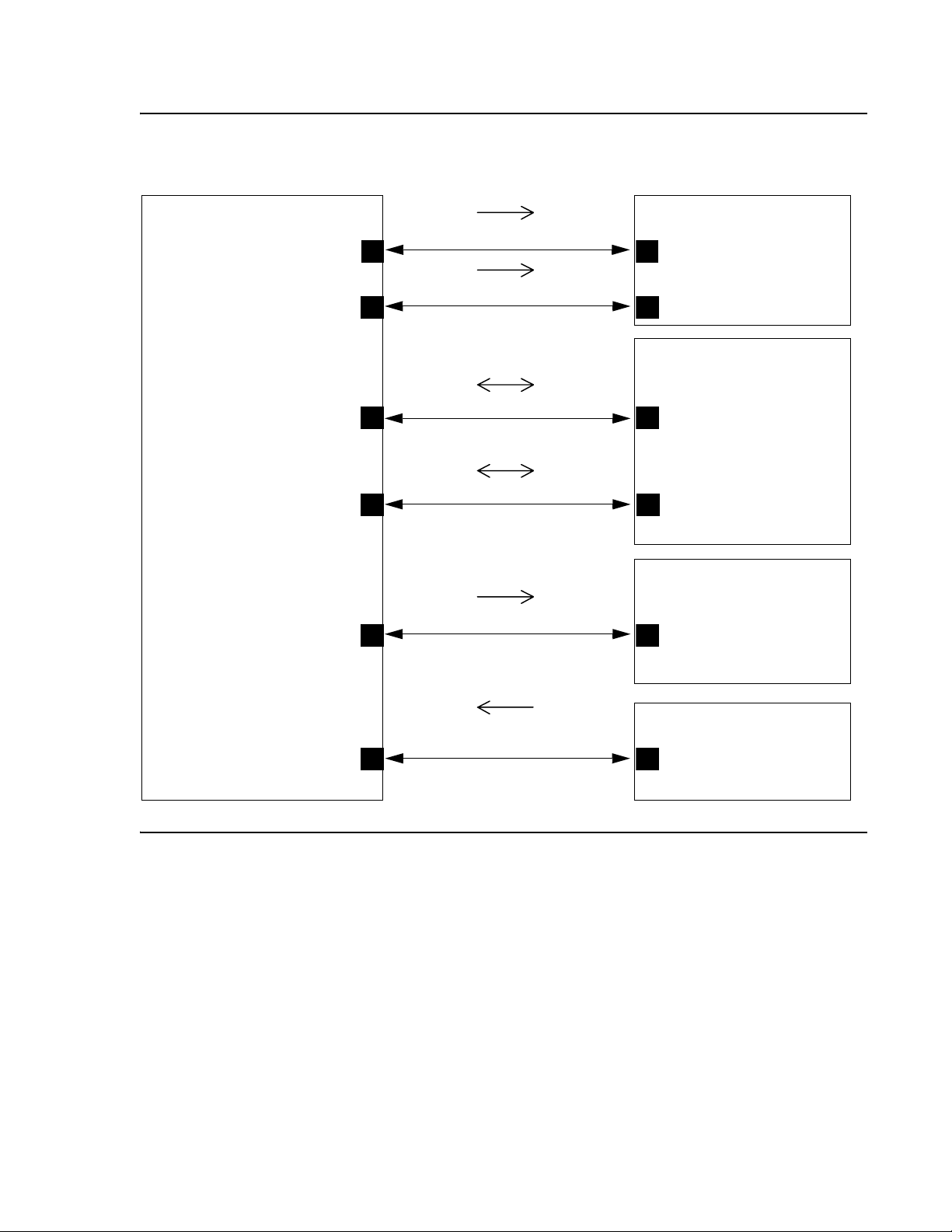
In Figure 1
● The box on the left always represents the 1600 Series IP Telephone.
● Depending on the diagram, the boxes on the right refer to various pieces of network
● Open-headed arrows (for example, ) represent the direction(s) of socket
and Figure 2:
equipment with which the telephone can communicate.
initialization.
on page 34.
● Closed-headed arrows (for example, ) represent the
direction(s) of data transfer.
● The text the arrows point to identifies the port or ports that the 1600 Series IP Telephones
support for the specific situation. Brackets identify ranges when more than one port
applies. The text indicates any additional qualifications or clarifications. In many cases, the
ports used are the ones called for by IETF or other standards bodies.
Issue 5 April 2010 27
Page 28
Network Requirements
Figure 1: Signaling, Audio and Management Diagram
Signaling, Audio and Management
1600 Series IP Telephone
Port: 49300
Port: [1500–6500]
randomly selected
Port: [4000–10000]
randomly selected;
range may be changed via
Gatekeeper administration;
always an even number
Port: audio port + 1
(only active during a call
if RTCP is enabled)
Port: audio port + 2
(only active during a call
if RTCP monitoring
is enabled)
H.323 RAS (UDP/IP)
H.323 Signaling (TCP/IP)
H.323 Gatekeeper
Port: 1719
Port: 1720
Media Gateway or
another IP endpoint
RTP Audio (UDP/IP)
Port selected from the
audio port range
administered for the
network region
RTCP (UDP/IP)
Port: audio port + 1
Voice Monitoring
Manager
RTCP (UDP/IP)
Port depends on Voice
Monitoring Manager
admin
SNMP (UDP/IP)
Port:161
28 Avaya 1600 Series IP Deskphones Administrator Guide
SNMP MIB Viewer
Port depends on
MIB viewer admin
Page 29
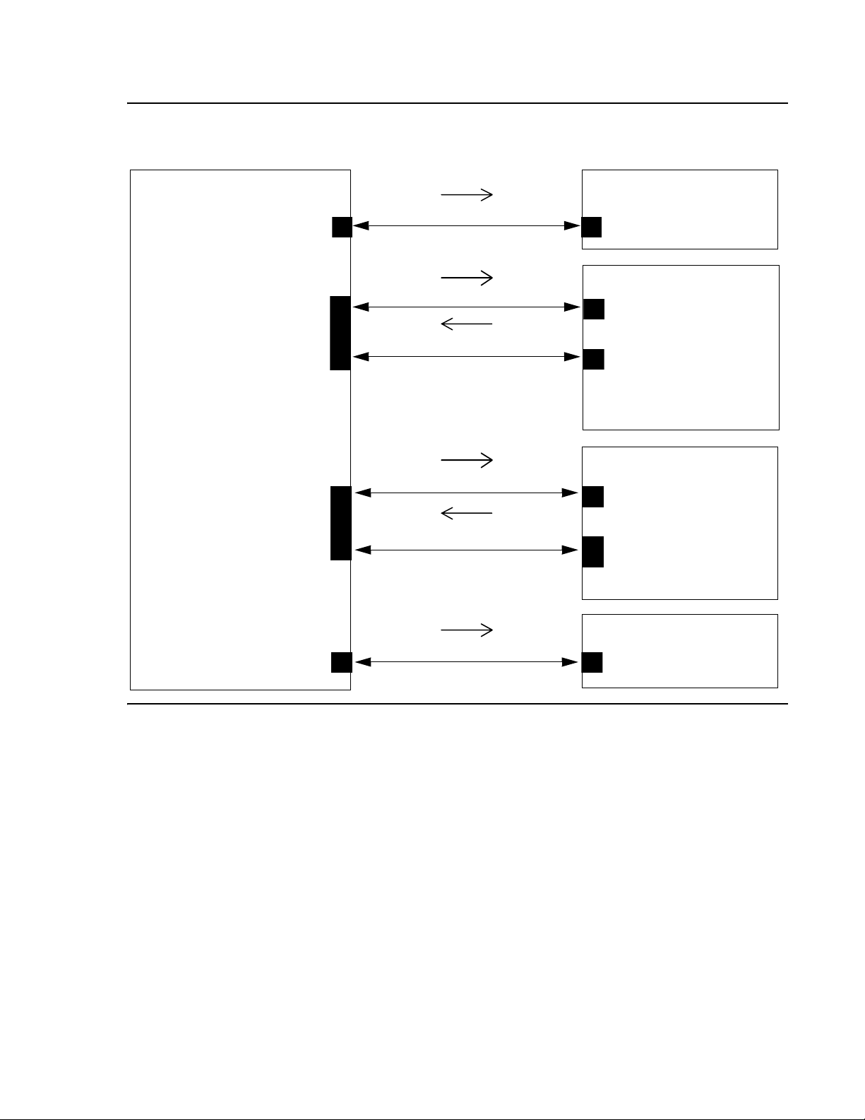
Figure 2: Initialization and Address Resolution Diagram
Initialization and Address Resolution
Other Network Considerations
1600 Series IP Telephone
Port: 68
Port: [1024 - 5000]
Operating System
–selected (a new port is
used for each file
requested)
Port: [1024 - 5000]
Operating System –
selected (a new port
is used for each file
requested)
HTTPS Read Request (TCP/IP)
HTTPS Data, ACKs & Errors (TCP/IP)
HTTP Read Request (TCP/IP)
HTTPS Data, ACKs & Errors (TCP/IP)
DHCP (TCP/IP)
DHCP Server
Port: 67
HTTPS Server
Port:411
Port: Operating
System – selected (a
new port is used for
each file
HTTP Server
Port: 80
Port: Operating System
– selected (a new port is
used for each file)
Port: [1024 - 5000]
Operating System
–selected
DNS(UDP/IP)
DNS Server
Port: 53
Issue 5 April 2010 29
Page 30

Network Requirements
Security
For information about toll fraud, see the DEFINITY®, Avaya Aura Communication Manager, or
Avaya Aura Communication Manager Branch documents on the Avaya support Web site. The
1600 Series IP Telephones cannot guarantee resistance to all Denial of Service attacks.
However, there are checks and protections to resist such attacks while maintaining appropriate
service to legitimate users.
You also have a variety of optional capabilities to restrict or remove how crucial network
information is displayed or used. These capabilities are covered in more detail in
Chapter 5:
● Support signaling channel encryption while registering, and when registered, with
Note: Signaling and audio are not encrypted when unnamed registration is effective.
● Restricting the response of the 1600 Series IP Telephones to SNMP queries to only IP
Server Administration.
appropriately administered Avaya Media Servers.
Note:
addresses on a list you specify.
● Specifying an SNMP community string for all SNMP messages the telephone sends.
● Restricting dialpad access to Local Administration Procedures, such as specifying IP
addresses, with a password.
● Removing dialpad access to most Local Administration Procedures.
● Restricting the end user’s ability to use a telephone Options application to view network
data.
As of Release 1.1, three existing security-related parameters can be administered on the call
server and downloaded with encrypted signaling, in addition to unencrypted HTTP or encrypted
HTTPS. Those parameters are SNMP community string, SNMP Source IP Addresses, and
Craft Access Code (PROCPSWD).
Registration and Authentication
The Avaya Media Server supports using the extension and password to register and
authenticate 1600 Series IP Telephones. For more information, see the current version of your
call server administration manual.
30 Avaya 1600 Series IP Deskphones Administrator Guide
Page 31

Chapter 4: Avaya Aura Communication Manager
Administration
Call Server Requirements
Before you perform administration tasks, ensure that the proper hardware is in place, and your
call server software is compatible with the 1600 Series IP Telephones. Avaya recommends the
latest PBX software and the latest IP telephone firmware.
Switch Compatibility and Aliasing IP Telephones
As of Release 1.1, 1600 Series IP Telephones were natively supported by Avaya Aura
Communication Manager Release 5.2. Native support means that if you have Avaya Aura
Communication Manager Release 5.2, you:
● do not have to alias 1600 Series IP Telephones,
● can add up to two BM32 Button Modules on each 1616 Series IP Telephone, and
● can administer a call coverage telephone number on a station-by-station basis.
If you have Avaya Aura Communication Manager Release 5.1 or earlier, you must alias the
telephones as follows:
1600 Series
Telephone Model
1603 4610 Avaya Aura Communication
1603-I 4610 Avaya Aura Communication
1603SW 4610 Avaya Aura Communication
1603SW-I 4610 Avaya Aura Communication
1608 4610 Avaya Aura Communication
Aliased as... Earliest Avaya Aura
Communication Manager Release
Manager 3.0
Manager 3.0
Manager 3.0
Manager 3.0
Manager 3.0
Issue 5 April 2010 31
Page 32

Avaya Aura Communication Manager Administration
1600 Series
Telephone Model
Aliased as... Earliest Avaya Aura
1608-I 4610 Avaya Aura Communication
1616 4620 Avaya Aura Communication
1616-I 4620 Avaya Aura Communication
BM32 EU24 Avaya Aura Communication
The 1603, 1603SW, 1603-I, and 1603SW-I IP Telephones support three administrable call
appearances or feature buttons. The 1608 and 1608-I IP Telephones support eight
administrable call appearances or feature buttons. The 1616 and 1616-I IP Telephones support
16 administrable call appearances or feature buttons. In addition, the 1616/1616-I IP
Telephones support the BM32 Button Module. The 1616/1616-I always support a single BM32,
and with Avaya Aura Communication Manager Release 5.2 or later, support up to two BM32
Button Modules per telephone.
Communication Manager Release
Manager 3.0
Manager 3.0
Manager 3.0
Manager 3.0
The BM32 Button Module provides another 32 administrable call appearances and features.
When attached to a 1616/1616-I IP Telephone that is aliased as a 4620, the first 16
administered call appearances and features are placed directly on the telephone, and the next
32 administered call appearances and features are placed on the button module, for a total of
48 administrable buttons.
For more information about aliasing one telephone model as another, see “Using an Alias” in
the Administrator Guide for Avaya Aura™ Communication Manager (Document 03-300509).
Avaya Aura Communication Manager Branch systems provide native support for the 1600
Series Telephones. See the Avaya Aura Communication Branch Device Manager online help
for more information.
32 Avaya 1600 Series IP Deskphones Administrator Guide
Page 33

Media Server (Switch) Administration
If you are using the 1600 Series IP Telephones with Avaya Aura Communication Manager, see
the following documents on the Avaya support Web site for information about specific switch
administration:
● The Administrator Guide for Avaya Aura™ Communication Manager (Document
03-300509) provides detailed instructions for administering an IP telephone system on
Avaya Aura Communication Manager. See Chapter 3 “Managing Telephones,” which
describes the process of adding new telephones. Also, you can locate pertinent screen
illustrations and field descriptions in Chapter 19 “Screen References” of that guide.
● Administration for Network Connectivity for Avaya Aura™ Communication Manager
(Document Number 555-233-504) provides detailed information about switch
administration for your network.
If you are using the 1600 Series IP Telephones with Avaya Aura Communication Manager
Branch, see the Avaya Aura Communication Manager Branch Device Manager online help for
information about specific switch administration.
Media Server (Switch) Administration
IP Interface and Addresses
If you are using the 1600 Series IP Telephones with Avaya Aura Communication Manager,
follow these general guidelines:
● Define the IP interfaces for each CLAN and Media processor circuit pack on the switch that
uses the IP Interfaces screen. For more information, see Administration for Network
Connectivity for Avaya Aura™ Communication Manager (Document 555-233-504).
● On the Customer Options form, verify that the IP Stations field is set to “y” (Yes). If it is
not, contact your Avaya sales representative. The IP Softphone field does not have to be
set to “y” (Yes).
If you are using the 1600 Series IP Telephones with Avaya Aura Communication Manager
Branch, see the Avaya Aura Communication Manager Branch Device Manager online help for
information about administering these telephones.
Issue 5 April 2010 33
Page 34

Avaya Aura Communication Manager Administration
UDP Port Selection
The 1600 Series IP Telephones can be administered from the Avaya Aura Communication
Manager Network Region form to support UDP port selection. Locate specific port assignment
diagrams in the 1600 IP Telephone Installation and Maintenance Guide. For information about
Avaya Aura Communication Manager implementation, see Administration for Network
Connectivity for Avaya Aura™ Communication Manager (Document Number 555-233-504) on
the Avaya support Web site.
Administer the switch to use a port within the proper range for the specific LAN, and the IP
telephone(s) copy that port. If no UDP port range is administered on the switch, the IP
telephone uses an even-numbered port, randomly selected from the interval 4000 to 10000.
RSVP and RTCP
Avaya IP Telephones implement the Resource ReSerVation Protocol (RSVP) administered from
the media server and the RTP Control Protocol (RTCP). The Avaya Voice over IP (VoIP)
Monitoring Manager (VMON) software can then provide real-time monitoring and historical data
of audio quality for VoIP calls.
The only way to change these parameters is by appropriate switch administration. For more
information, see your Avaya Media Server administration documentation and Administration for
Network Connectivity for Avaya Aura™ Communication Manager (Document Number
555-233-504).
QoS
The 1600 Series IP Telephones support both IEEE 802.1P/Q and DiffServ. Other
network-based QoS initiatives such as UDP port selection do not require support by the
telephones. However, they contribute to improved QoS for the entire network.
IEEE 802.1P and 802.1Q
The 1600 Series IP Telephones can simultaneously support receipt of packets using, or not
using, 802.1Q parameters. To support IEEE 802.1P/Q, you can administer 1600 Series IP
Telephones from the network by appropriate administration of the DHCP or HTTP/HTTPS
servers, or by using dialpad input at the telephone.
34 Avaya 1600 Series IP Deskphones Administrator Guide
Page 35

NAT
Media Server (Switch) Administration
!
Important:
Important: Avaya Aura Communication Manager administration always takes precedence
over manual administration of IEEE 802.1P/Q data.
The four IEEE 802.IP/Q QoS parameters in the telephones that can be administered on the IP
Network Region form are L2Q, L2QVLAN, L2QAUD, and L2QSIG. To set these parameters at
the switch, see “About Quality of Service (QoS) and voice quality administration” in
Administration for Network Connectivity for Avaya Aura™ Communication Manager (Document
Number 555-233-504). To set these parameters manually see the 1600 IP Telephone
Installation and Maintenance Guide. You can specify VLAN ID and VLANTEST values with the
ADDR Local Administrative Option.
Note:
Note: All local administrative procedures are on a phone-by-phone basis.
Administration using Avaya Aura Communication Manager, DHCP, and HTTP
applies to the telephone system itself or to a range of telephones.
Network Address Translation (NAT) usage can lead to problems that affect the consistency of
addressing throughout your network. All H.323 IP Telephones support NAT interworking.
Support for NAT does not imply support for Network Address Port Translation (NAPT). The
telephones do not support communication to the PBX through any NAPT device.
NAT requires specific administration on the media server. A direct Avaya IP Telephone-to-Avaya
IP Telephone call with NAT requires Avaya Aura Communication Manager Release 3.0 or
greater software. For more information, see Administration for Network Connectivity for Avaya
Aura™ Communication Manager (Document Number 555-233-504) on the Avaya support Web
site.
DIFFSERV
The DiffServ values change to the values administered on the media server as soon as the
telephone registers. For more information, see Chapter 4 “Network Quality Administration” in
Administration for Network Connectivity for Avaya Aura™ Communication Manager (Document
Number 555-233-504). Unless there is a specific need in your enterprise LAN, Avaya
recommends that you do not change the default values.
Issue 5 April 2010 35
Page 36

Avaya Aura Communication Manager Administration
Voice Mail Integration
1600 Series IP Telephones with Avaya Aura Communication Manager 5.2 Native Support
Release 1.1 provides native support for 1600 Series IP Telephones running on Avaya Aura
Communication Manager Release 5.2 or later. When native support applies, pressing the
Messages button causes the telephone to first determine if the call server has a dedicated
number for retrieving voice mail and when found, to proceed with voice mail retrieval.
1600 Series IP Telephones Aliased as 4600 Series IP Telephones
When native support does not apply, 1600 Series IP Telephones are aliased as 4600 Series IP
Telephones and run under an Avaya Aura Communication Manager Release earlier than 5.2. In
this case, use the settings file to configure the Messages button by setting the system
parameter MSGNUM
to any dialable string. MSGNUM examples are:
● a standard telephone number the telephone should dial to access your voice mail system,
such as AUDIX or Octel.
● a Feature Access Code (FAC) that allows users to transfer an active call directly to voice
mail. FACs are supported only for QSIG-integrated voice mail systems like AUDIX or
Octel. QSIG is an enhanced signaling system that allows the voice mail system and Avaya
Aura Communication Manager Automated Call Processing (ACP) to exchange
information.
When the user presses the Messages button on the telephone, that number or FAC is
automatically dialed, giving the user one-touch access to voice mail.
The settings file specifies the telephone number to be dialed automatically when the user
presses this button. The command is:
SET MSGNUM 1234
where 1234 is the Voice Mail extension (Avaya Aura Communication Manager hunt group or
VDN). For more information, see Table 8
MSGNUM is used both in native support and when the telephone is aliased using non-native
support. Messaging must be configured for native support.
A separate Voice Mail extension can be administered for each station.
.
36 Avaya 1600 Series IP Deskphones Administrator Guide
Page 37

Telephone Administration
This section describes how to administer Avaya Aura Communication Manager for 1600 Series
IP Telephones. For detailed information about administering Avaya Aura Communication
Manager, see the following Avaya documents:
● Administrator Guide for Avaya Aura™ Communication Manager (Document 03-300509).
● Feature Description and Implementation for Avaya Aura™ Communication Manager
(Document 555-245-770).
For detailed information about administering Avaya Aura Communication Manager Branch for
1600 Series IP Telephones, see the Avaya Aura Communication Manager Branch Device
Manager online help.
System-Wide Administration
This section refers to Avaya Aura Communication Manager administration on the Switch
Administration Terminal (SAT) or by Avaya Site Administration. The system wide Avaya Aura
Communication Manager form and the particular page that needs to be administered for each
feature are provided. These features, which already exist, are not required but are
recommended because they optimize the telephone user interface. Avaya Aura Communication
Manager Release 3.0 or greater is required.
Telephone Administration
Note:
Note: See Appendix C: Sample Administration Forms for illustrated examples of the
pages used to administer Avaya Aura Communication Manager features.
Feature-Related System Parameters
Release 1.1 supports the functionality introduced on Avaya Aura Communication Manager
Release 5.2 that allows call server administration of three system-wide parameters. By
administering these parameters on Avaya Aura Communication Manager, they can be
automatically downloaded to the telephone during registration, instead of or in addition to from
the settings file or locally per telephone. The three system parameters are: SNMP community
Issue 5 April 2010 37
Page 38

Avaya Aura Communication Manager Administration
string, SNMP Source IP addresses, and Craft Access Code (PROCPSWD). Administer these
three parameters using Page 3 of the change system-parameters ip-options form.
Avaya Aura Communication Manager Feature Administration
Feature Administration
On-Hook Dialing Set up Avaya Aura Communication Manager so that the phone
supports on-hook dialing. Use the System Parameters Features
form page 10. Use the command Change
system-parameters features to view the form and make
the change.
Auto Hold Set up Avaya Aura Communication Manager to enable Auto
Hold, so that the phone automatically places an active call on
hold when the user answers or resumes a call on another call
appearance. Use the System Parameters Features form, page 6
Coverage Path Administer a coverage path for both phone demonstration and
normal operations. Use the Coverage Path form and give it a
number, for example, Coverage path 1. If Voice Mail is available,
this is also where you administer the hunt group or VDN,
depending on the type of Voice Mail system being used.
.
Enhanced Conference
Features
Enable enhanced conference display to support the user
experience for conferences. Block Enhanced Conference Display
on the Class of Restriction (COR) form must be set to No. Use
the command Change COR, followed by a number, to view the
form and make the change. a sample of the Class of Restriction
form.
Administering Stations
This section refers to Avaya Aura Communication Manager administration on the Switch
Administration Terminal (SAT) or by Avaya Site Administration. Administer the following items
on the Station form, sample screens of which are provided in Figure 3
recommends setting the features covered in this section because they optimize the user
interface.
Release 1.1 supports the functionality introduced on Avaya Aura Communication Manager
Release 5.2 that allows call server administration of the GROUP parameter on a
station-by-station basis. As covered in The GROUP System Value
Identifier can be used in conjunction with the 46xxsettings file to allow administration to apply to
specific “groups” of telephones. Before Release 1.1, the Group Identifier had to be administered
locally on each applicable telephone. As of Release 1.1, the Group Identifier can be
administered centrally, and downloaded to each applicable telephone. The GROUP ID
parameter is administered on page 3 of the Change Station Form. Once downloaded, the Group
Identifier takes effect starting with the next telephone boot-up.
through Figure 6. Avaya
on page 65, the GROUP
38 Avaya 1600 Series IP Deskphones Administrator Guide
Page 39

For sample Station Forms, see Appendix C: Sample Administration Forms.
Aliasing 1600 Series IP Telephones
Avaya Aura Communication Manager releases earlier than 5.2 do not provide native support for
1600 Series IP Telephones. On the Station Form, administer (alias) the telephones as follows:
Change Alias Station:
● Alias set up type 1603/1603SW/1603-I/1603SW-I to a 4610
● Alias set up type 1608/1608-I to a 4610
● Alias set up type 1616/1616-I to a 4620SW/4621SW
Avaya Aura Communication Manager Release 5.2 (and later) provides native support for the
1603,1603SW, 1603-I, 1603SW-I, 1608, 1608-I, 1616, and 1616-I.
Administering Features
Administering Stations
The following are administrable Station Features that Avaya recommends you administer for
your 1600 Series IP Telephones for maximum user experience.
Administrable Station Features
Feature Administration
Enhanced Conference
Features
Administer Conf-dsp (conference display) on the station form as
a feature button. Doing so turns on enhanced conference
features and gives users advanced conference features.
Far End Mute Administer fe-mute (far end mute). When this is enabled the
phone shows a “Silence” softkey on the Conference details
screen. This feature works only for trunk calls.
Send All Calls (SAC) On the Station form, administer SAC (send-calls) as a feature
button. On the Station form to the right of where send all calls is
administered, leave the extension box empty. This feature
requires a coverage path to be administered on the station form.
Coverage Path For normal operation, you must set up a coverage path for each
telephone. Administer the Station form to point to the appropriate
system coverage path, for example, coverage path 1.
Auto select any idle
appearance
Restrict Last Call
Set Auto select any idle appearance to N (no) to optimize
answering calls.
Set Restrict Last Call Appearance to Y (yes).
Appearance
Conference/Transfer on
Primary Appearance
Set Conference/Transfer on Primary Appearance to Y (yes) to
ensure that conference/transfer of a bridged appearance works
properly.
Issue 5 April 2010 39
Page 40

Avaya Aura Communication Manager Administration
Feature Buttons and Call Appearances
For the 1603/1603SW/1603-I/1603SW-I and 1608/1608-I IP Telephones
You can administer Feature/Call Appearance Buttons 1 – 8 on the Avaya Aura Communication
Manager Station form, which the telephone Feature screen then displays in sequence. The
telephone does not display any of the Feature Button labels administered on buttons 9 – 24.
These telephones do not support the BM32 Button Module.
For the 1616/1616-I IP Telephones
You can administer Feature/Call Appearance Buttons 1 – 16 on the Avaya Aura Communication
Manager Station form. The features administered on the Station form appear in the same
sequence on the telephone Feature screen. Features administered on the Expansion Module
BM32 Call Appearance buttons display on the telephone Features screen following the first 16
administered feature buttons. All administered BM32 Button Labels (Call Appearances and
Feature Buttons) display on the corresponding BM32 module buttons.
In Table 5
screen, as applicable to the button type.
Table 5: Station Form Administration Results
Feature / Call Appearance (CA) /
Bridged Call Appearance (BA)
buttons on the Station form...
1 Phone screen Phone screen Phone screen
2 to 16 CAs/BAs on
17 to 48 N/A N/A First BM32
49 to 80 N/A N/A Second BM32
the term “phone screen” refers to either the call appearance screen or the features
Is displayed on
the phone as:
1603/1603SW
1603-I/1603SW-I
Phone screen;
must scroll to
see more than 1
1608/1608-I 1616/1616-I
CAs/BAs on
Phone screen;
must scroll to
see more than 1
CAs/BAs on
Phone screen;
must scroll to
see more than 1
40 Avaya 1600 Series IP Deskphones Administrator Guide
Page 41

For additional information about administering the call server for 1600 Series IP Telephones,
see the following Avaya documents, available on the Avaya Support Web site:
● Administrator Guide for Avaya Aura™ Communication Manager (Document Number
03-300509).
● Feature Description and Implementation for Avaya Aura™ Communication Manager
(Document Number 555-245-770).
Conference Details Screen for Ad-Hoc Conferences
Conference Details allows the user to view parties on a conference call and selectively mute or
drop individual parties for a conference call setup.
If administered on an Expansion Module button, the BM32 Button Module must be connected.
To enable Conference Details capabilities:
1. On the Class of Restriction (COR) form make sure that Block Enhanced Conference/
Transfer Displays is set to No.
Shuffling
2. As described in On-Hook Dialing
Phone button on the Phone screen.
Shuffling
Administer shuffling on three forms:
● Feature-Related Parameters form, shown in Figure 7. Set the Direct IP-IP Audio
Connections? field to y (yes).
● IP Network Region form, shown in Figure 11. Set both the Intra-region IP-IP Direct Audio
field and the Inter-region IP-IP Direct Audio field to y (yes).
● Station form, shown in Figure 4. Set the Direct IP-to-IP Audio Connection to y (yes). The
Station form setting overrides the network region, which overrides the system setting.
, administer the Conference Display Feature Button to a
Issue 5 April 2010 41
Page 42

Avaya Aura Communication Manager Administration
Printing Button Labels
You can download software from www.desi.com that enables you to print button labels for the
1600 series telephones. To download this software, perform the following steps:
1. Using your web browser, go to www.desi.com.
2. Click DESI downloads.
3. Download the appropriate application.
If you are using Avaya Aura Communication Manager Branch, you can export the button
settings from Local Manager and import the settings into the DESI application. For more
information, see the Avaya Aura Communication Manager Branch Device Manager online help.
42 Avaya 1600 Series IP Deskphones Administrator Guide
Page 43

Chapter 5: Server Administration
Software Checklist
Ensure that you own licenses to use the DHCP, HTTP, and HTTPS server software.
Note:
Note: You can install the DHCP and HTTP server software on the same machine.
!
CAUTION:
CAUTION: The firmware in the 1600 Series IP Telephones reserves IP addresses of the form
192.168.0.24 and 192.168.1.x for internal communications. The telephone(s)
improperly use addresses you specify if they are of that form.
DHCP and File Servers
Dynamic Host Configuration Protocol (DHCP) minimizes maintenance for a 1600 Series IP
Telephone network by removing the need to individually assign and maintain IP addresses and
other parameters for each IP telephone on the network.
The DHCP server provides the following information to the 1600 Series IP Telephones:
● IP address of the 1600 Series IP Telephone(s)
● IP address of the Gatekeeper board on the Avaya Media Server
● IP address of the HTTP or HTTPS server
● The subnet mask
● IP address of the router
● DNS Server IP address
Administer the LAN so each IP telephone can access a DHCP server that contains the IP
addresses and subnet mask.
The IP telephone cannot function without an IP address. The failure of a DHCP server at boot
time leaves all the affected telephones unusable. A user can manually assign an IP address to
an IP telephone. When the DHCP server finally returns, the telephone never looks for a DHCP
server unless the static IP data is unassigned manually. In addition, manual entry of IP data is
an error-prone process.
Issue 5 April 2010 43
Page 44

Server Administration
Avaya recommends that:
● A minimum of two DHCP servers be available for reliability.
● A DHCP server be available when the IP telephone reboots.
● A DHCP server be available at remote sites if WAN failures isolate IP telephones from the
central site DHCP server(s).
The file server provides the 1600 Series IP Telephone with a script file and, if appropriate, new
or updated application software. See Step 3: Telephone and File Server
Telephone Initialization Process
. In addition, you can edit an associated settings file to
customize telephone parameters for your specific environment. For more information, see
Chapter 7:
Administering Telephone Options.
DHCP Server Administration
This document concentrates on the simplest case of the single LAN segment. Information
provided here can be used for more complex LAN configurations.
on page 18 under
!
CAUTION:
CAUTION: Before you start, understand your current network configuration. An improper
installation can cause network failures or reduce the reliability and performance
of your network.
DHCP Generic Setup
This document is limited to describing a generic administration that works with the 1600 Series
IP Telephones. Three DHCP software alternatives are common to Windows operating systems:
● Windows NT
● Windows 2000
● Windows 2003
®
4.0 DHCP Server
®
DHCP Server
®
DHCP Server
44 Avaya 1600 Series IP Deskphones Administrator Guide
Page 45

DHCP Server Administration
Any other DHCP application might work. It is the responsibility of the customer to install and
configure the DHCP server correctly.
DHCP server setup involves:
1. Installing the DHCP server software according to vendor instructions.
2. Configuring the DHCP server with:
● IP addresses available for the 1600 Series IP Telephones.
● The following DHCP options:
- Option 1 - Subnet mask.
As described in Table 3
, item 3.
- Option 3 - Gateway (router) IP address(es).
As described in Table 3
, item 1. If using more than one address, the total list can
contain up to 255 total ASCII characters. You must separate IP addresses with
commas with no intervening spaces.
- Option 6 - DNS server(s) address list.
If using more than one address, the total list can contain up to 127 total ASCII
characters. You must separate IP addresses with commas with no intervening spaces.
At least one address in Option 6 must be a valid, non zero, dotted decimal address.
- Option 12 - Host Name.
Value is AVohhhhhh, where: o is “A” if the OID (first three octets) of the MAC address
for the telephone is 00-04-0D. “E” if the OID is 00-09-6E, “L” if the OID is 00-60-1D,
and “X” if the OID is anything else and where hhhhhh are ASCII characters for the
hexadecimal representation of the last three octets of the MAC address for the
telephone.
- Option 15 - DNS Domain Name.
This string contains the domain name to be used when DNS names in system
parameters are resolved into IP addresses. This domain name is appended to the
DNS name before the 1600 IP Telephone attempts to resolve the DNS address.
Option 15 is necessary if you want to use a DNS name for the HTTP server.
Otherwise, you can specify a DOMAIN as part of customizing HTTP as indicated in
DNS Addressing
on page 76.
- Option 51 - DHCP lease time.
If this option is not received, the DHCPOFFER is not be accepted. Avaya
recommends a lease time of six weeks or greater. If this option has a value of
FFFFFFFF hex, the IP address lease is assumed to be infinite as per RFC 2131,
Section 3.3, so that renewal and rebinding procedures are not necessary even if
Options 58 and 59 are received. Expired leases cause Avaya IP Telephones to reboot.
Avaya recommends providing enough leases so an IP address for an IP telephone
does not change if it is briefly taken offline.
Issue 5 April 2010 45
Page 46

Server Administration
Note:
Note: The DHCP standard states that when a DHCP lease expires, the device should
immediately cease using its assigned IP address. If the network has problems
and the only DHCP server is centralized, the server is not accessible to the given
telephone. In this case the telephone is not usable until the server can be
reached.
Avaya recommends, once assigned an IP address, the telephone continues
using that address after the DHCP lease expires, until a conflict with another
device is detected. As Ta bl e 8:
Parameters indicates, the system parameter DHCPSTD allows an administrator
to specify that the telephone will either:
a). Comply with the DHCP standard by setting DHCPSTD to “1”, or
b). Continue to use its IP address after the DHCP lease expires by setting
DHCPSTD to “0.”
The latter case is the default. If the default is invoked, after the DHCP lease
expires the telephone sends an ARP Request for its own IP address every five
seconds.
The request continues either forever, or until the telephone receives an ARP
Reply. After receiving an ARP Reply, the telephone displays an error message,
sets its IP address to 0.0.0.0, and attempts to contact the DHCP server again.
1600 Series IP Telephone Customizable System
- Option 52 - Overload Option, if desired.
If this option is received in a message, the telephone interprets the sname and file
fields in accordance with IETF RFC 2132,
Section 9.3, listed in Appendix B: Related Documentation
.
- Option 53 - DHCP message type.
Value is 1 (DHCPDISCOVER) or 3 (DHCPREQUEST).
- Option 55 - Parameter Request List.
Acceptable values are:
1 (subnet mask),
3 (router IP address[es])
6 (domain name server IP address[es])
15 (domain name)
NVSSON (site-specific option number)
- Option 57 - Maximum DHCP message size.
- Option 58 - DHCP lease renew time.
If not received or if this value is greater than that for Option 51, the default value of T1
(renewal timer) is used as per IETF RFC 2131, Section 4.5, listed in Related
Documentation.
- Option 59 - DHCP lease rebind time.
If not received or if this value is greater than that for Option 51, the default value of T2
(rebinding timer) is used as per RFC 2131, Section 4.5
46 Avaya 1600 Series IP Deskphones Administrator Guide
Page 47

DHCP Server Administration
The 1600 Series IP Telephones do not support Regular Expression Matching, and therefore, do
not use wildcards. For more information, see Administering Options for the
1600 Series IP
Telephones on page 67.
In configurations where the upgrade script and application files are in the default directory on
the HTTP server, do not use the HTTPDIR=<path>.
You do not have to use Option 242. If you do not use this option, you must ensure that the key
information, especially HTTPSRVR and MCIPADD, is administered appropriately elsewhere.
Avaya recommends that you administer DHCP servers to deliver only the options specified in
this document. Administering additional, unexpected options might have unexpected results,
including causing the IP telephone to ignore the DHCP server.
The media server name and HTTP server name must each be no more than 32 characters in
length.
Examples of good DNS administration include:
- Option 6: “aaa.aaa.aaa.aaa”
- Option 15: “dnsexample.yourco.com,zzz.zzz.zzz.zzz”
- Option 242: “MCIPADD=xxxx.xxx.xxx.xxx”
Depending on the DHCP application you choose, be aware that the application most
likely does not immediately recycle expired DHCP leases. An expired lease might
remain reserved for the original client a day or more. For example, Windows NT
®
DHCP reserves expired leases for about one day. This reservation period protects a
lease for a short time. If the client and the DHCP server are in two different time
zones, the clocks of the computers are not in sync, or the client is not on the network
when the lease expires, there is time to correct the situation.
The following example shows the implication of having a reservation period: Assume
two IP addresses, therefore two possible DHCP leases. Assume three IP telephones,
two of which are using the two available IP addresses. When the lease for the first two
telephones expires, the third telephone cannot get a lease until the reservation period
expires. Even if the other two telephones are removed from the network, the third
telephone remains without a lease until the reservation period expires.
Issue 5 April 2010 47
Page 48

Server Administration
In Table 6, the 1600 Series IP Telephone sets the system values to the DHCPACK message
field values shown.
Table 6: DHCPACK Setting of System Values
System Value Set to
IPADD The yiaddr field.
NETMASK Option #1 (if received).
GIPADD Option #3 (if received, which might be a list of IP
TLSSRVR The siaddr field, if that field is non-zero.
HTTPSRVR The siaddr field, if that field is non-zero.
DNSSRVR Option #6 (if received, which might be a list of IP
DOMAIN Option #15 (if received).
DHCP lease time Option #51 (if received).
addresses).
addresses).
DHCP lease renew time Option #58 (if received).
DHCP lease rebind time Option #59 (if received).
The system values L2Q, L2QVLAN, and PHY2VLAN are not set from a name=value pair if
those system values were previously set by LLDP. For more information, see Link Layer
Discovery Protocol (LLDP).
Windows NT 4.0 DHCP Server
Verifying the Installation of the DHCP Server
Use the following procedure to verify whether the DHCP server is installed.
1. Select Start-->Settings-->Control Panel.
2. Double-click the Network icon.
3. Verify that Microsoft DHCP Server is listed as one of the Network Services on the
Services tab.
4. If it is listed, continue with the next section. If it is not listed, install the DHCP server.
48 Avaya 1600 Series IP Deskphones Administrator Guide
Page 49

Creating a DHCP Scope for the IP Telephones
Use the following procedure to create a DHCP scope for the IP telephones.
1. Select Start-->Programs-->Admin Tools-->DHCP Manager.
2. Expand Local Machine in the DHCP Servers window by double clicking it until the + sign
changes to a - sign.
3. Select Scope-->Create.
DHCP Server Administration
4. Using information recorded in Tab le 3:
Required Network Information Before Installation -
Per DHCP Server:
Define the Telephone IP Address Range.
Set the Subnet Mask.
To exclude any IP addresses you do not want assigned to IP telephones within the Start
and End addresses range:
a. In the Exclusion Range Start Address field, enter the first IP Address in the range that
you want to exclude.
b. In the Exclusion Range End Address field, enter the last IP Address in the range that
you want to exclude.
c. Click the Add button.
d. Repeat steps a. through c. for each IP address range to be excluded.
Note:
Note: Avaya recommends that you provision the 1600 Series IP Telephones with
sequential IP addresses. Also do not mix 1600 Series IP Telephones and PCs in
the same scope.
5. Under Lease Duration, select the Limited To option and set the lease duration to the
maximum.
6. Enter a sensible name for the Name field, such as “DEFINITY IP Telephones.”
7. Click OK.
A dialog box prompts you: Activate the new scope now?
8. Click No.
Note:
Note: Activate the scope only after setting all options.
Issue 5 April 2010 49
Page 50

Server Administration
Editing Custom Options
Use the following procedure to edit custom options.
1. Highlight the newly created scope.
2. Select DHCP Options-->Defaults in the menu.
3. Click the New button.
4. In the Add Option Type dialog box, enter an appropriate custom option name, for example,
“1600OPTION.”
5. Change the Data Type Byte value to String.
6. Enter 242 in the Identifier field.
7. Click the OK button.
The DHCP Options menu displays.
8. Select the Option Name for 242 and set the value string.
9. Click the OK button.
10. For the Option Name field, select 003 Router from the drop-down list.
11. Cl ick Edit Array.
12. Enter the Gateway IP Address recorded in Table 3:
Installation - Per DHCP Server for the New IP Address field.
13. Select Add and then OK.
Adding the DHCP Option
Use the following procedure to add the DHCP option.
1. Highlight the scope you just created.
2. Select Scope under DHCP Options.
3. Select the 242 option that you created from the Unused Options list.
4. Click the Add button.
5. Select option 003 from the Unused Options list.
6. Click the Add button.
7. Click the OK button.
8. Select the Global parameter under DHCP Options.
9. Select the 242 option that you created from the Unused Options list.
Required Network Information Before
10. Click the Add button.
11. Click the OK button.
50 Avaya 1600 Series IP Deskphones Administrator Guide
Page 51

Activating the Leases
Use the following procedure to activate the leases.
● Click Activate under the Scope menu.
The light-bulb icon for the scope lights.
Verifying Your Configuration
DHCP Server Administration
This section describes how to verify that the 1600OPTION is correctly configured for the
Windows NT
®
4.0 DHCP server.
Note:
Note: Although this configuration represents that for 1600 Series IP Telephones, the file
remains as 46XXOPTIONS. This allows shared use by 4600, 9600, and 1600
Series IP Telephones.
Verify the Default Option, 242 1600OPTION
1. Select Start-->Programs-->Admin Tools-->DHCP Manager.
2. Expand Local Machine in the DHCP servers window by double clicking until the + sign
changes to a - sign.
3. In the DHCP servers frame, click the scope for the IP telephone.
4. Select Defaults from the DHCP_Options menu.
5. In the Option Name pull-down list, select 242 1600OPTION.
6. Verify that the Value String box contains the correct string from DHCP Server
Administration.
If not, update the string and click the OK button twice.
Verify the Scope Option, 242 1600OPTION
1. Select Scope under DHCP OPTIONS.
2. In the Active Options: scroll list, click 242 1600OPTION.
3. Click the Value button.
4. Verify that the Value String box contains the correct string from DHCP Generic Setup
page 44.
If not, update the string and click the OK button.
Issue 5 April 2010 51
on
Page 52

Server Administration
Verify the Global Option, 242 1600OPTION
1. Select Global under DHCP OPTIONS.
2. In the Active Options: scroll list, click 242 1600OPTION.
3. Click the Value button.
4. Verify that the Value String box contains the correct value from DHCP Generic Setup
page 44.
If not, update the string and click the OK button.
Windows 2000 DHCP Server
Verifying the Installation of the DHCP Server
Use the following procedure to verify whether the DHCP server is installed.
1. Select Start-->Program-->Administrative Tools-->Computer Management.
2. Under Services and Applications in the Computer Management tree, find DHCP.
3. If DHCP is not installed, install the DHCP server. Otherwise, proceed directly to Creating
and Configuring a DHCP Scope for instructions on server configuration.
Creating and Configuring a DHCP Scope
Use the following procedure to create and configure a DHCP scope.
1. Select Start-->Programs-->Administrative Tools-->DHCP.
2. In the console tree, click the DHCP server to which you want to add the DHCP scope for the
IP telephones. This is usually the name of your DHCP server machine.
3. Select Action-->New Scope from the menu.
on
Windows displays the New Scope Wizard to guide you through rest of the setup.
4. Click the Next button.
The Scope Name dialog box displays.
5. In the Name field, enter a name for the scope such as “DEFINITY IP Telephones,” then
enter a brief comment in the Description field.
6. When you finish Steps 1 - 5, click the Next button.
The IP Address Range dialog box displays.
7. Define the range of IP addresses used by the IP telephones listed in Table 3:
Network Information Before Installation - Per DHCP Server. The Start IP Address is the
first IP address available to the IP telephones. The End IP Address is the last IP address
available to the IP telephones.
Note:
Note: Avaya recommends not mixing 1600 Series IP Telephones and PCs in the same
scope.
52 Avaya 1600 Series IP Deskphones Administrator Guide
Required
Page 53

DHCP Server Administration
8. Define the subnet mask in one of two ways:
● The number of bits of an IP address to use for the network/subnet IDs.
● The subnet mask IP address.
Enter only one of these values. When you finish, click the Next button.
The Add Exclusions dialog box displays.
9. Exclude any IP addresses in the range specified in the previous step that you do not want
assigned to an IP telephone.
a. In the Start Address field under Exclusion Range, enter the first IP Address in the
range you want to exclude.
b. In the End Address field under Exclusion Range, enter the last IP Address in the
range you want to exclude.
c. Click the Add button.
d. Repeat steps a. through c. for each IP address range that you want to exclude.
Note:
Note: You can add additional exclusion ranges later by right clicking the Address Pool
under the newly created scope and selecting the New Exclusion Range option.
Click the Next button after you enter all the exclusions.
The Lease Duration dialog box displays.
10. For all telephones that obtain their IP addresses from the server, enter 30 days in the
Lease Duration field. This is the duration after which the IP address for the device expires
and which the device needs to renew.
11. Click the Next button.
The Configure DHCP Options dialog box displays.
12. Click the No, I will activate this scope later button.
The Router (Default Gateway) dialog box displays.
13. For each router or default gateway, enter the IP Address and click the Add button.
When you are done, click the Next button.
The Completing the New Scope Wizard dialog box displays.
14. Click the Finish button.
The new scope appears under your server in the DHCP tree. The scope is not yet active
and does not assign IP addresses.
15. Highlight the newly created scope and select Action-->Properties from the menu.
Issue 5 April 2010 53
Page 54

Server Administration
16. Under Lease duration for DHCP clients, select Unlimited and then click the OK button.
!
CAUTION:
CAUTION: IP address leases are kept active for varying periods of time. To avoid having
calls terminated suddenly, make the lease duration unlimited.
Adding DHCP Options
Use the following procedure to add DHCP options to the scope you created in the previous
procedure.
1. On the DHCP window, right-click the Scope Options folder under the scope you created in
the last procedure.
A drop-down menu displays.
2. In the left pane of the DHCP window, right click the DHCP Server name, then click Set
Predefined Options....
3. Under Predefined Options and Values, click Add.
4. In the Option Type Name field, enter any appropriate name, for example, “Avaya IP
Telephones.”
5. Change the Data Type to String.
6. In the Code field, enter 242, then click the OK button twice.
The Predefined Options and Values dialog box closes, leaving the DHCP dialog box
enabled.
7. Expand the newly created scope to reveal its Scope Options.
8. Click Scope Options and select Action-->Configure Options from the menu.
9. In the General tab page, under the Available Options, check the Option 242 checkbox.
10. In the Data Entry box, enter the DHCP IP telephone option string as described in
DHCP Generic Setup
on page 44.
Note:
Note: You can enter the text string directly on the right side of the Data Entry box under
the ASCII label.
11. From the list in Available Options, check option 003 Router.
12. Enter the gateway (router) IP Address from the IP address field of Table 3:
Required
Network Information Before Installation - Per DHCP Server.
13. Click the Add button.
14. Click the OK button.
54 Avaya 1600 Series IP Deskphones Administrator Guide
Page 55

Activating the New Scope
Use the following procedure to activate the new scope.
1. In the DHCP console tree, click the IP Telephone Scope you just created.
2. From the Action menu, select Activate.
The small red down arrow over the scope icon disappears, indicating that the scope was
activated.
HTTP Generic Setup
You can store the same application software, script file, and settings file on an HTTP server as
you can on a TFTP server. TFTP is not supported for 1600 Series IP Telephones. With proper
administration, the telephone seeks out and uses that material. Some functionality might be lost
by a reset if the HTTP server is unavailable. For more information, see DHCP and File
Servers on page 43.
HTTP Generic Setup
!
CAUTION:
CAUTION: The files defined by HTTP server configuration must be accessible from all IP
telephones invoking those files. Ensure that the file names match the names in
the upgrade script, including case, since UNIX systems are case-sensitive.
Note:
Note: Use any HTTP application you want. Commonly used HTTP applications include
Apache
!
Important:
Important: You must use the Avaya Web configuration server to obtain HTTPS so
®
and Microsoft® IIS™.
information is authenticated.
The Avaya Web configuration server does not support backup/restore. If you
intend to use HTTP for backup/restore purposes, you must use an HTTP server
that is independent of the Avaya Web configuration server.
To set up an HTTP server:
● Install the HTTP server application.
● Administer the system parameter HTTPSRVR to the address(es) of the HTTP server.
Include these parameters in DHCP Option 242, or the appropriate SSON Option.
Issue 5 April 2010 55
Page 56

Server Administration
● Download the upgrade script file and application file(s) from the Avaya Web site
http://www.avaya.com/support
Contents of the Settings File
to the HTTP server. For more information, see
on page 64.
Note:
Note: Many LINUX servers distinguish between upper and lower case names. Ensure
that you specify the settings file name accurately, as well as the names and
values of the data within the file.
If you choose to enhance the security of your HTTP environment by using Transport Layer
Security (TLS), you also need to:
● Install the TLS server application.
● Administer the system parameter TLSSRVR to the address(es) of the Avaya HTTPS
server.
HTTP Configuration for Backup/Restore
For IIS Web Servers
For IIS 4.0 (WinNT4.0), IIS 5.0 (Win2000), IIS 5.1 (WinXP), IIS 6.0 (Win2003):
1. Create a “backup” folder under the root directory of your Web server. All backup files will be
stored in that directory.
For example, if your backup folder is C:/Inetpub/wwwroot/backup the 46xxsettings.txt file
should have a line similar to:
[SET BRURI http://www.website.com/backup/
If your backup folder is the root directory, the 46xxsettings.txt file should have a line similar
to:
[SET BRURI http://www.website.com/
2. Use Internet Information Services Manager or Internet Information Services depending
on your OS. Go to Start --> Settings --> Control Panel --> Administrative Tools.
3. Right click on the folder created for backup, or right click on Default Web Site if there is no
specific backup directory.
4. Select Properties.
5. In the Directory tab, make sure the Write box is checked.
]
]
56 Avaya 1600 Series IP Deskphones Administrator Guide
Page 57

HTTP Configuration for Backup/Restore
Additional step for IIS 6.0 (Win2003):
1. Use Internet Information Services. Go to Start --> Settings --> Control Panel -->
Administrative Tools.
2. Below Default Web Site select Web Services Extension.
3. Make sure the WebDAV option is set to Allowed.
For Apache Web servers:
1. Create a “backup” folder under the root directory of your Web server, and make the folder
writable by everyone. All backup files will be stored in that directory.
If your backup folder is for instance C:/Program Files/Apache Group/Apache2/htdocs/
backup, the 46xxsettings.txt file should have a line similar to:
[SET BRURI http://www.website.com/backup/
]
If your backup folder is the root directory, the 46xxsettings.txt file should have a line similar
to:
[SET BRURI http://www.website.com/
]
2. Edit your Web server configuration file httpd.conf.
3. Uncomment the two LoadModule lines associated with DAV:
LoadModule dav_module modules/mod_dav.so
LoadModule dav_fs_module modules/mod_dav_fs.so
Note:
Note: If these modules are not available on your system, typically the case on some
Unix/Linux Apache servers, you have to recompile these two modules (mod_dav
& mod_dav_fs) into the server. Other ways to load these modules might be
available. Check your Apache documentation at http://httpd.apache.org/docs/
more details.
4. Add the following lines in the httpd.conf file:
#
# WebDAV configuration
#
DavLockDB "C:/Program Files/Apache Group/Apache2/var/DAVLock"
for
<Location />
Dav On
</Location>
For Unix/Linux Web servers the fourth line might look more like:
DavLockDB/usr/local/apache2/var/DAVLock
5. Create the var directory and make it writable by everyone. Right click
Properties-->Security-->Add-->Everyone-->Full Control.
Issue 5 April 2010 57
Page 58

Server Administration
Web Configuration Tool
Recent call server versions provide all the Web configuration support the 1600 Series IP
Telephones require. Also, the media server has an easy to use, PC-based interface for creating
script files. Given these resources, you do not need to manually create the text files discussed
in 16
00 Series IP Telephone Scripts and Application Files. For more information about the
media server, see Installation and Upgrades for Avaya G700 Media Gateway and Avaya S8300
Media Server, available on the Avaya support Web site.
Table 8:
1600 Series IP Telephone Customizable System Parameters lists the parameters you
can administer when manually creating the configuration file. Manual administration is
discussed in 16
00 Series IP Telephone Scripts and Application Files. When using the media
server, you do not need to know the specific parameter names, since the media server handles
that. For more information, Tab le 7
lists the parameter names from 1600 Series IP Telephone
Customizable System Parameters and the corresponding field name from the media server
HTTP server application. Any limits, restrictions, etc. about the parameters are built into the
media server.
Note:
Note: The Web Configuration application covers other IP telephones in addition to the
1600 Series IP Telephones. This document covers only data applicable to 1600
Series IP Telephones.
Table 7: Media Server Field Names & Corresponding Script File Parameter
Names
Media Server Field Name Script File Parameter Name
Handset Audio Gain Control Status AGCHAND
Headset Audio Gain Control Status AGCHEAD
Speaker Audio Gain Control Status AGCSPKR
Application Status APPSTAT
Script File Server Authentication
Note: Applicable only when configuration file
downloaded using HTTPS. Not applicable if file
downloaded using HTTP.
Idle Time Before Backlight Turnoff BAKLIGHTOFF
Backup and Restore URI BRURI
CNA Server Addresses CNASRVR
58 Avaya 1600 Series IP Deskphones Administrator Guide
AUTH
1 of 3
Page 59

Web Configuration Tool
Table 7: Media Server Field Names & Corresponding Script File Parameter
Names (continued)
Media Server Field Name Script File Parameter Name
CNA Port Number CNAPORT
802.1X Supplicant Mode DOT1X
DOT1XSTAT
DHCP Lease Violation Flag DHCPSTD
Domain Name DOMAIN
Domain Name Server DNSSRVR
HTTP Server IP Address HTTPSRVR
HTTP Directory HTTPDIR
Send Destination Unreachable Messages ICMPDU
Process Received Redirect Messages ICMPRED
Layer 2 Frame Tagging L2Q
802.1A VLAN Identifier L2QVLAN
System-Wide Language LANGSYS
English Language Selection Status LANG0STAT
Language File Name LANGxFILE (with x being 1-4)
Font File Name FONTFILE
Event Log Security Level LOGLOCAL
Syslog Server Address LOGSRVR
Management Complex IP Addresses MCIPADD
Voice Mail Telephone Number MSGNUM
User Options Access OPSTAT
Telephone Country Code PHNCC
Telephone Dial Plan Length PHNDPLENGTH
International Access Code PHNIC
Long Distance Access Code PHNLD
2 of 3
Issue 5 April 2010 59
Page 60

Server Administration
Table 7: Media Server Field Names & Corresponding Script File Parameter
Names (continued)
Media Server Field Name Script File Parameter Name
National Telephone # Length PHNLDLENGTH
Outside Line Access Code PHNOL
Ethernet Line Interface Status PHY1STAT
Secondary Ethernet Interface Layer 2 Priority Value PHY2PRIO
Secondary Ethernet Line Interface Status PHY2STAT
Secondary Ethernet Interface VLAN Identifier PHY2VLAN
Local (dial pad) Procedure Password PROCPSWD
Local Dialpad Procedures Allowed PROCSTAT
Reregistration Timer REREGISTER
RTCP Monitor IP Address RTCPMON
Source IP Addresses for SNMP Queries SNMPADD
SNMP Community String SNMPSTRING
Subscription List SUBSCRIBELIST
Trusted Domains/Paths TPSLIST
Unnamed Registration Status UNNAMEDSTAT
Secondary Ethernet Interface Layer 2 Frame Tagging VLANSEP
Wait Time for DHCP Offer VLANTEST
3 of 3
60 Avaya 1600 Series IP Deskphones Administrator Guide
Page 61

Chapter 6: Telephone Software and Application
Files
General Download Process
The 1600 Series IP Telephones download script files and settings files from either an HTTP or
HTTPS server. These telephones download the application files from the HTTP server. The
HTTPS server applies only if the server supports Transport Layer Security (TLS) encryption.
Note:
Note: The script files, application files, and settings files discussed in this chapter are
identical for HTTP and HTTPS servers. The generic term “file server” refers to
both “HTTP server” and “HTTPS server.”
The file downloading process is the same for both servers, except when you use an HTTPS
server, a TLS server is contacted first. The telephone queries the file server, which transmits a
script file to the telephone. The script file tells the telephone which application file the telephone
must use. The application file is the software that has the telephony functionality, and is easily
updated for future enhancements. In a newly installed telephone, the application file might be
missing. In a previously installed telephone, the application file might not be the proper one. In
both cases, the telephone requests a download of the proper application file from the HTTP
server. The file server downloads the file and conducts some checks to ensure that the file was
downloaded properly. If the telephone determines it already has the proper file, the telephone
proceeds to the next step without downloading the application file again.
After checking and loading the application file, the 1600 Series IP Telephone, if appropriate,
uses the script file to look for a settings file. The settings file contains options you have
administered for any or all of the 1600 Series IP Telephones in your network. For more
information about the settings file, see Contents of the Settings File
Software
When shipped from the factory, the1600 Series IP Telephones might not contain sufficient
software for registration and operation. When the telephone is first plugged in, a software
download from an HTTP server starts to give the phone its proper functionality.
For software upgrade downloads, the call server provides the capability for a remote restart of
the 1600 Series IP Telephone. As a result of restarting, the telephone automatically starts
reboot procedures. If new software is available on the server, the telephone downloads it as part
of the reboot process. The Avaya 1600 Series IP Deskphones Installation and Maintenance
Guide covers upgrades to a previously installed telephone and related information.
on page 64.
Issue 5 April 2010 61
Page 62

Telephone Software and Application Files
1600 Series IP Telephone Scripts and Application Files
Choosing the Right Application File and Upgrade Script File
The software releases containing the files needed to operate the 1600 Series IP Telephones are
bundled together. You download this self-extracting executable file to your file server from the
Avaya support Web site at: http://www.avaya.com/support
and unzipped format.
The bundle contains:
● An upgrade script file and a settings file, which allow you to upgrade to new software
releases and new functionality without having to replace IP telephones.
● Application files for all current 1600 Series IP Telephones.
● Other useful information such as a ReadMe file and a settings file template to customize
parameters and settings, and the latest binary code.
. The file is available in both zipped
● Font files
● Language files
Upgrade Script File
An upgrade script file tells the IP telephone whether the telephone needs to upgrade software.
The Avaya IP Telephones attempt to read this file whenever they reset. The upgrade script
file also points to the settings file.
You download a default upgrade script file, sometimes called the “script file,” from
http://www.avaya.com/support
customer-definable options. This file must reside in the same directory as the upgrade script
file, and must be called 46xxsettings.txt. The settings file contains settings for 1600, 9600, and
4600 Series IP Telephones.
Note:
Note: Avaya recommends that the settings file have the extension *.txt. The Avaya IP
Telephones can operate without this file. You can also change these settings with
DHCP or, in some cases, from the dialpad of the telephone.
. This file allows the telephone to use default settings for
62 Avaya 1600 Series IP Deskphones Administrator Guide
Page 63

Settings File
The settings file contains the option settings you need to customize the Avaya IP Telephones for
your enterprise.
Note:
Note: You can use one settings file for all your Avaya IP Telephones. The settings file
includes the 1600 Series IP Telephones covered in this document as well as
9600 Series IP Telephones and 4600 Series IP Telephones.
The settings file can include any of five types of statements, one per line:
● Comments, which are statements with a “#” character in the first column.
● Tags, which are comments that have exactly one space character after the initial #,
followed by a text string with no spaces.
● Goto commands, of the form GOTO tag. Goto commands cause the telephone to
continue interpreting the configuration file at the next line after a # tag statement. If no
such statement exists, the rest of the configuration file is ignored.
● Conditionals, of the form IF $name SEQ string GOTO tag. Conditionals cause the Goto
command to be processed if the value of name is a case-insensitive equivalent to string.
If no such name exists, the entire conditional is ignored. The only system values that can
be used in a conditional statement are: BOOTNAME, GROUP, and SIG.
● SET commands, of the form SET parameter_name value. Invalid values cause the
specified value to be ignored for the associated parameter_name so the default or
previously administered value is retained. All values must be text strings, even if the
value itself is numeric, a dotted decimal IP address, and so on.
1600 Series IP Telephone Scripts and Application Files
Note:
Note: Enclose all data in quotation marks for proper interpretation.
The upgrade script file Avaya provides includes a line that tell the telephone to GET
46xxsettings.txt. This lines causes the telephone to use HTTP or HTTPS to attempt to
download the file specified in the GET command. If the file is obtained, its contents are
interpreted as an additional script file. That is how your settings are changed from the default
settings. If the file cannot be obtained, the telephone continues processing the upgrade script
file.
If the configuration file is successfully obtained but does not include any setting changes the
telephone stops using HTTP. This happens when you initially download the script file template
from the Avaya support Web site, before you make any changes. When the configuration file
contains no setting changes, the telephone does not go back to the upgrade script file.
Avaya recommends that you do not alter the upgrade script file. If Avaya changes the upgrade
script file in the future, any changes you have made will be lost. Avaya recommends that you
use the 46xxsettings file to customize your settings instead. However, you can change the
settings file name, if desired, as long as you also edit the corresponding GET command in the
upgrade script file.
For more information on customizing your settings file, see Contents of the Settings File
.
Issue 5 April 2010 63
Page 64

Telephone Software and Application Files
Contents of the Settings File
After checking the application software, the 1600 Series IP Telephone looks for a 46xxsettings
file. This optional file is where you identify non-default option settings, application-specific
parameters, and so on. You can download a template for this file from the Avaya support Web
site. An example of what the file might look like follows.
Note:
Note: The following is intended only as a simple example. Your settings will vary from
the settings shown. This sample assumes specification of a DNS Server and
turning off enhanced local dialing for 96xx Series IP Telephones.
DNSSRVR=”dnsexample.yourco.com”
ENDIALSTAT=0
See Chapter 7:
Administering Telephone Options for details about specific values. You
need only specify settings that vary from defaults, although specifying defaults is
harmless.
VLAN separation controls whether or not traffic received on the secondary Ethernet interface
are forwarded on the voice VLAN and whether network traffic received on the data VLAN are
forwarded to the telephone. Add commands to the 46xxsettings.txt file to enable VLAN
separation. The following example assumes the voice VLAN ID is “xxx”, the data VLAN ID is
“yyy” and the data traffic priority is “z”:
SET VLANSEP 1
SET L2Q 1 (or 0 for auto)
SET L2QVLAN xxx
SET PHY2VLAN yyy
SET PHY2PRIO z
Note:
Note: Also configure the network switch so that 802.1Q tags are not removed from
frames forwarded to the telephone.
64 Avaya 1600 Series IP Deskphones Administrator Guide
Page 65

The GROUP System Value
You might have different communities of users, all of which have the same telephone model, but
which require different administered settings. For example, you might want to restrict Call
Center agents from being able to Logoff, which might be an essential capability for “hot-desking”
associates. We provide examples of the group settings for each of these situations later in this
section.
Use the GROUP system value for this purpose:
1. identify which telephones are associated with which group, and designate a number for
each group. The number can be any integer from 0 to 999, with 0 as the default, meaning
your largest group is assigned as Group 0.
2. At each non-default telephone, instruct the installer or user to invoke the GROUP Local
(dialpad) Administrative procedure as specified in the Avaya 1600 Series IP Deskphones
Installation and Maintenance Guide and specify which GROUP number to use. The
GROUP System value can only be set on a phone-by-phone basis.
3. Once the GROUP assignments are in place, edit the configuration file to allow each
telephone of the appropriate group to download its proper settings.
The GROUP System Value
Here is an example of the configuration file for the Call Center agent:
IF $GROUP SEQ 1 goto CALLCENTER
IF $GROUP SEQ 2 goto HOTDESK
{specify settings unique to Group 0}
goto END
# CALLCENTER
{specify settings unique to Group 1}
goto END
# HOTDESK
{specify settings unique to Group 2}
# END
{specify settings common to all Groups}
Issue 5 April 2010 65
Page 66

Telephone Software and Application Files
66 Avaya 1600 Series IP Deskphones Administrator Guide
Page 67

Chapter 7: Administering Telephone Options
Administering Options for the 1600 Series IP Telephones
This chapter explains how to change parameters by means of the DHCP or HTTP servers. In all
cases, you are setting a system parameter in the telephone to a desired value. Tabl e 8
● the parameter names,
● their default values,
● the valid ranges for those values, and
● a description of each one.
For DHCP, the DHCP Option sets these parameters to the desired values as discussed in
DHCP and File Servers
values in the script file. For more information, see Contents of the Settings File
When using a media server, see Tab le 7 :
on page 43. For HTTP, the parameters in Tab le 8 are set to desired
on page 64.
Media Server Field Names & Corresponding Script
File Parameter Names on page 58 for information on parameters set by the media server
application.
lists:
Avaya recommends that you administer options on the 1600 Series IP Telephones using script
files. Some DHCP applications have limits on the amount of user-specified information. The
administration required can exceed those limits for the more full-featured telephone models.
You might choose to completely disable the capability to enter or change option settings from
the dialpad. You can set the system value, PROCPSWD, as part of standard DHCP/HTTP
administration. Alternately, you can set PROCPSWD on the system-parameters ip-options form,
as of Avaya Aura Communication Manager Release 5.2. If PROCPSWD is non-null and
consists of 1 to 7 digits, the user cannot invoke any “dialpad options” without first pressing Mute
and entering the PROCPSWD value. For more information on dialpad options, see the Avaya
1600 Series IP Deskphones Installation and Maintenance Guide.
!
CAUTION:
CAUTION: PROCPSWD is likely stored on the server “in the clear” and is sent to the
telephone in the clear. Therefore, do not consider PROCPSWD as a
high-security technique to inhibit a sophisticated user from obtaining access to
local procedures.
Administering this password can limit access to all local procedures, including
V I E W. VIEW is a read-only option that allows review of the current telephone
settings.
Issue 5 April 2010 67
Page 68

Administering Telephone Options
Table 8: 1600 Series IP Telephone Customizable System Parameters
Parameter Name Default Value Description and Value Range
AGCHAND 1 Automatic Gain Control status for handset
AGCHEAD 1 Automatic Gain Control status for headset
AGCSPKR 1 Automatic Gain Control status for Speaker
APPNAME " " (Null) Primary application image file name, as provided in the
APPSTAT 1 Controls whether specific applications are enabled,
AUTH 0 Script file authentication value (0=HTTP is acceptable,
BAKLIGHTOFF 120 Number of minutes without display activity to wait
BRURI " " (Null) URL used for backup and retrieval of user data. Specify
DHCPSTD 0 DHCP Standard lease violation flag. Indicates whether
DNSSRVR 0.0.0.0 Text string containing the IP address of zero or more
DOMAIN " " (Null) Text string containing the domain name to be used
DOT1X 0 802.1X Supplicant operation mode. Valid values are:
(0=disabled, 1=enabled).
(0=disabled, 1=enabled).
(0=disabled, 1=enabled).
1600upgrade.txt file.
restricted, or disabled. Values are: 1=all applications
enabled, 2=Speed Dial (Contacts) changes and Call
Log disabled and Redial last number only, 3=Speed
Dial (Contacts) changes disabled, 0=Speed Dial
(Contacts) changes, Call Log, and Redial disabled.
1=HTTPS is required).
before turning off the backlight. Values: 0-999, no
spaces and no null value. A value of 0 means the
backlight never turns off.
HTTP server and directory path to backup file. Do not
specify backup file name. Value: 0-255 ASCII
characters. Null is a valid value and spaces are
allowed.
to keep the IP address if there is no response to lease
renewal. If set to “1” (No) the telephone strictly follows
the DHCP standard with respect to giving up IP
addresses when the DHCP lease expires. If set to “0”
(Yes) the telephone continues using the IP address
until it detects reset or a conflict (see DHCP Generic
Setup).
DNS servers, in dotted-decimal format, separated by
commas with no intervening spaces (0-255 ASCII
characters, including commas).
when DNS names in system values are resolved into
IP addresses. Valid values are 0-255 ASCII characters.
If Null, no spaces allowed.
0=With PAE pass-through, 1=with PAE pass-through
and proxy Logoff, 2=without PAE pass-through or
proxy Logoff. For more information, see
IEEE
802.1X on page 77.
1 of 6
68 Avaya 1600 Series IP Deskphones Administrator Guide
Page 69

Administering Options for the 1600 Series IP Telephones
Table 8: 1600 Series IP Telephone Customizable System Parameters (continued)
Parameter Name Default Value Description and Value Range
DOT1XSTAT 0 Determines how the telephone handles Supplicants.
Valid values are:
0=Supplicant operation is completely disabled.
1=Supplicant operation is enabled, but responds only
to received unicast EAPOL messages.
2=Supplication operation is enabled and responds to
received unicast and multicast EAPOL messages. For
more information, see
IEEE 802.1X on page 77.
ENHDIALSTAT 1 Enhanced Dialing Status. If set to “1” the Enhanced
Local Dialing feature is turned on for all associated
applications. If set to “0” the feature is turned off.
FONTFILE " " (Null) Name of the font file for a language for a 1600 Series
International telephone.
HTTPDIR " " (Null) HTTP server directory path. The path name prepended
to all file names used in HTTP and HTTPS get
operations during initialization. Value: 0-127 ASCII
characters, no spaces. Null is a valid value. Leading or
trailing slashes are not required.
HTTPSRVR " " (Null) Text list of HTTP server addresses in dotted decimal or
DNS format, separated by commas (0-255 ASCII
characters, including commas).
ICMPDU 0 Controls whether ICMP Destination Unreachable
messages will be processed. Values are: 0=No,
1=Send limited Port Unreachable messages, 2=Send
Protocol and Port Unreachable messages.
ICMPRED 0 Controls whether ICMP Redirect messages will be
processed. Values are: 0=No, 1=Yes.
L2Q 0 Controls whether Layer 2 frames have IEEE 802.1Q
tags (0=auto, 1=enabled, 2=disabled).
L2QVLAN 0 802.1Q VLAN Identifier (0 to 4094). Null (" ") is not a
valid value and the value cannot contain spaces. VLAN
identifier used by IP telephones. Set this parameter
only when IP telephones are to use a VLAN that is
separate from the default data VLAN. If the VLAN
identifier is to be configured via H.323 signaling based
on Avaya Aura Communication Manager
administration forms, it should not be set here.
LANG0STAT 1 Controls whether the built-in English language text
strings can be selected by the user. Valid values are:
0 = User cannot select English language text strings
1 = User can select English language text strings/
LANGxFILE " " (Null) Name of the language file in use:
LANG1FILE =
LANG2FILE =
LANG3FILE =
LANG4FILE =
2 of 6
Issue 5 April 2010 69
Page 70

Administering Telephone Options
Table 8: 1600 Series IP Telephone Customizable System Parameters (continued)
Parameter Name Default Value Description and Value Range
LANGSYS " " (Null) 0 to 32 ASCII characters. The file name of the system
LOGLOCAL 0 Event Log Severity Level (one 0-8 ASCII numeric
LOGSRVR " " (Null) Voice Monitoring Manager (VMM) Server Address.
MCIPADD 0.0.0.0 Call Server Address. Zero or more Avaya Aura
MSGNUM " " (Null) Voice mail telephone number. Specifies the number to
OPSTAT 111 Options status flag(s) (1 or 3 ASCII numeric digits)
default language file, if any.
digit). Controls the level of events logged in the
endptRecentLog and endptResetLog objects in the
SNMP MIB. Events with the selected level and with a
higher severity level will be logged. Valid values are:
0=Disabled, 1=emergencies, 2=alerts, 3=critical,
4=errors, 5=warnings, 6=notices, 7=information,
8=debug.
Zero or one IP address in dotted-decimal format or
DNS Name format (0-15 ASCII characters).
Communication Manager server IP addresses. Format
is dotted-decimal or DNS name format, separated by
commas without intervening spaces (0-255 ASCII
characters, including commas). Null is a valid value.
be dialed automatically when the telephone user
presses the Message button. Value: 0-30 ASCII
dialable characters (0-9, * and #) and no spaces. Null
is a valid value.
indicate which options are user-selectable. The default
of 111 grants access to all options and related
applications.
Single digit valid values are:
1=user can access all options, including Logout,
2= user can access only view-oriented applications.
Three-digit valid values are a concatenation of binary
values, in the form abc, where each letter represents a
0 (disabled/off) or 1 (enabled/on), interpreted as:
a = base settings for all user options and related
applications, except as noted in b or c.
b = setting for view-oriented applications (for example,
the Network Information application), as applicable.
c = setting for Logout application, if applicable.
The binary "0" does not allow an end user to see or
invoke options and related applications. The binary "1"
allows full display and access to all options and related
applications.
PHNCC 1 Telephone country code. The administered
international country code for the location by the
algorithm that dials calls from the incoming Call Log or
from Web pages. Range: 1-3 digits, from “1” to “999.”
70 Avaya 1600 Series IP Deskphones Administrator Guide
3 of 6
Page 71

Administering Options for the 1600 Series IP Telephones
Table 8: 1600 Series IP Telephone Customizable System Parameters (continued)
Parameter Name Default Value Description and Value Range
PHNDPLENGTH 5 Internal extension telephone number length. Specifies
the number of digits associated with internal extension
numbers by the algorithm that dials calls from the
incoming Call Log or from Web pages. Range: 1 or 2
digits, from “3” to “10.”
PHNIC 011 Telephone international access code. The maximum
number of digits, if any, dialed to access public network
international trunks by the algorithm that dials calls
from the incoming Call Log or from Web pages. Range:
0-4 digits.
PHNLD 1 Telephone long distance access code. The digit, if any,
dialed to access public network long distance trunks by
the algorithm that dials calls from the incoming Call Log
or from Web pages. Range: 1 digit or " " (Null).
PHNLDLENGTH 10 Length of national telephone number. The number of
digits in the longest possible national telephone
number by the algorithm that dials calls from the
incoming Call Log or from Web pages. Range: 1 or 2
digits, from “3” to “10.” Range: 1 or 2 ASCII numeric
characters, from “5” to “15.”
PHNOL 9 Outside line access code. The character(s) dialed,
including # and *, if any, to access public network local
trunks by the algorithm that dials calls from the
incoming Call Log or from Web pages. Range: 0-2
dialable characters, including " " (Null).
PHY1STAT 1 Ethernet line interface setting (1=auto-negotiate,
2=10Mbps half-duplex, 3=10Mbps full-duplex,
4=100Mbps half-duplex, 5=100Mbps full-duplex, and
6=1000Mbps full-duplex if supported by the hardware).
PHY2PRIO 0 Layer 2 priority value for frames received on or
forwarded to the secondary Ethernet interface. Set this
parameter only when VLAN separation is "1"
(enabled). Values are from 0-7 and correspond to the
drop-down menu selection.
PHY2STAT 1 Secondary Ethernet interface setting
(0=Secondary Ethernet interface off/disabled,
1=auto-negotiate, 2=10Mbps half-duplex, 3=10Mbps
full-duplex, 4=100Mbps half-duplex, 5=100Mbps
full-duplex), and 6=1000Mbps full-duplex if supported
by the hardware).
PHY2VLAN 0 VLAN identifier used by frames received on or
forwarded to the secondary Ethernet interface. Set this
parameter only when VLAN separation is "1"
(enabled). Value is 1-4 ASCII numeric digits from “0” to
“4094.” Null is not a valid value, nor can the value
contain spaces. If this value is set by LLDP using the
Port VLAN ID TLV value, it will not change regardless
of settings from other sources. For more information,
see Parameter Data Precedence
.
4 of 6
Issue 5 April 2010 71
Page 72

Administering Telephone Options
Table 8: 1600 Series IP Telephone Customizable System Parameters (continued)
Parameter Name Default Value Description and Value Range
PROCPSWD " " (Null) Text string containing the local (dialpad) procedure
PROCSTAT 0 Local (dialpad) Administrative procedures status
REREGISTER 20 Registration timer in minutes. Controls an H.323
RTCPMON " " (Null) Text string containing the 4-octet IP address of the
SNMPADD " " (Null) Text string containing zero or more allowable source IP
SNMPSTRING " " (Null) Text string containing the SNMP community name
STATIC 0 Static programming override flag. If set to “0” static
SUBSCRIBELIST " " (Null) One or more Push application server subscription
password (Null or 1-7 ASCII digits). If set, password
must be entered immediately after Mute is pressed and
before entry of a procedure command (for example,
VIEW). Intended to facilitate restricted access to local
procedures even when command sequences are
known. Password is viewable, not hidden.
(0=Local procedures enabled, 1=all Administrative
Options are disabled).
protocol timer that should only be changed under very
special circumstances by someone who fully
understands the system operation impact. Value is
1-120.
RTCP monitor currently in use, in dotted decimal or
DNS Name format (0-15 ASCII characters, no spaces).
addresses for SNMP queries, in dotted decimal or DNS
format, separated by commas, with up to 255 total
ASCII characters including commas.
string (up to 32 ASCII characters, no spaces).
programming never overrides call server (DHCP) or
call server administered data. If set to “1” static
programming overrides only file server administered
data. If set to “2” static programming overrides only call
server administered data. If set to “3” static
programming overrides both file server- and call
server-administered data. Allows a call server IP
address that has been manually programmed into a
telephone to override any value received via DHCP or
via this configuration file. A manually programmed IP
address will only be used if it is not 0.0.0.0, so this
parameter may be used to allow only specific
telephones to use a different value than otherwise
provided by this configuration file. If STATIC is to be
used to select a manual override of file server IP
address(es), STATIC must be set via DHCP, not via
this configuration file.
URLs, separated by commas without any intervening
spaces (0-255 ASCII characters, including commas).
5 of 6
72 Avaya 1600 Series IP Deskphones Administrator Guide
Page 73

VLAN Considerations
Table 8: 1600 Series IP Telephone Customizable System Parameters (continued)
Parameter Name Default Value Description and Value Range
TPSLIST " " (Null) One or more trusted domain/path strings, separated by
commas without any intervening spaces (0-255 ASCII
characters, including commas). A URL pushed to a
telephone must contain one of these strings if it is to be
used to obtain content to be rendered by the
telephone.
UNNAMEDSTAT 1 Unnamed Registration Status. Specifies whether
unnamed registration is initiated if the user fails to enter
a value at the Extension: prompt or Login screen.
Unnamed registration provides the telephone with a
TTI-level service, enabling a user, for example, to dial
emergency services like 911. Value 1=Yes, 0=No.
VLANSEP 1 VLAN separation. Controls whether frames to/from the
secondary Ethernet interface receive IEEE 802.1Q
tagging treatment. The tagging treatment enables
frames to be forwarded based on their tags in a
manner separate from telephone frames. If tags are not
changed, no tag-based forwarding is employed. Values
are: 1=On/Enabled, 0= Off/Disabled. This parameter is
used with several related parameters. For more
information, see VLAN Separation
on page 75.
VLANTEST 60 Number of seconds to wait for a DHCPOFFER when
using a non-zero VLAN ID (1-3 ASCII digits, from “0” to
“999”).
6 of 6
Note:
Note: Table 8 applies to all 1600 Series IP Telephones. Certain 1600 IP Telephones
might have additional, optional information that you can administer. For more
information, see Chapter 8:
VLAN Considerations
If your LAN environment does not include Virtual LANs (VLANs), ignore this section. Otherwise,
this section contains information on how to administer 1600 Series IP Telephones to minimize
registration time and maximize performance in a VLAN environment.
VLAN Tagging
IEEE 802.1Q tagging (VLAN) is a useful method of managing VoIP traffic in your LAN. Avaya
recommends that you establish a voice LAN, set L2QVLAN to that VLAN, and provide voice
traffic with priority over other traffic. If LLDP was used to set the telephones’ VLAN, that setting
Administering Applications and Options.
Issue 5 April 2010 73
Page 74

Administering Telephone Options
has absolute authority. Otherwise, you can set VLAN tagging manually, by DHCP, or in the
46xxsettings.txt file.
If VLAN tagging is enabled (L2Q=0 or 1), the 1600 Series IP Telephones set the VLAN ID to
L2QVLAN, and VLAN priority for packets from the telephone to L2QAUD for audio packets and
L2QSIG for signalling packets. The default value (6) for these parameters is the recommended
value for voice traffic in IEEE 802.1D.
Regardless of the tagging setting, a 1600 Series IP Telephone will always transmit packets from
the telephone at absolute priority over packets from secondary Ethernet. The priority settings
are useful only if the downstream equipment is administered to give the voice LAN priority.
VLAN Default Value and Priority Tagging
The system value L2QVLAN is initially set to “0” and identifies the 802.1Q VLAN Identifier. This
default value indicates “priority tagging” as defined in IEEE 802.IQ Section 9.3.2.3. Priority
tagging specifies that your network closet Ethernet switch automatically insert the switch port
default VLAN without changing the user priority of the frame (cf. IEEE 802.1P and 802.1Q).
If you do not want the default VLAN to be used for voice traffic:
● Ensure that the switch configuration lets frames tagged by the 1600 Series IP Telephone
through without overwriting or removing them.
● Set the system value L2QVLAN to the VLAN ID appropriate for your voice LAN.
Another system value you can administer is VLANTEST. VLANTEST defines the number of
seconds the 1600 IP Series Telephone waits for a DHCPOFFER message when using a
non-zero VLAN ID. The VLANTEST default is “60” seconds. Using VLANTEST ensures that the
telephone returns to the default VLAN if an invalid VLAN ID is administered or if the phone
moves to a port where the L2QVLAN value is invalid. The default value is long, allowing for the
scenario that a major power interruption is causing the phones to restart. Always allow time for
network routers, the DHCP servers, etc. to be returned to service. If the telephone restarts for
any reason and the VLANTEST time limit expires, the telephone assumes the administered
VLAN ID is invalid. The telephone then initiates registration with the default VLAN ID.
Setting VLANTEST to “0” has the special meaning of telling the phone to use a non-zero VLAN
indefinitely to attempt DHCP. In other words, the telephone does not return to the default VLAN.
Note:
Note: If the telephone returns to the default VLAN but must be put back on the
L2QVLAN VLAN ID, you must Reset the telephone. See the Reset procedure in
the Avaya 1600 Series IP Deskphones Installation and Maintenance Guide.
74 Avaya 1600 Series IP Deskphones Administrator Guide
Page 75

VLAN Separation
VLAN separation controls whether or not traffic received on the secondary Ethernet interface
can be forwarded on the voice VLAN. VLAN separation also controls whether network traffic
received on the data VLAN can be forwarded to the telephone. The following system
parameters control VLAN separation:
● VLANSEP - enables (1) or disables (0) VLAN separation. The default is 1 (on), which
allows full separation. When set to 0 (off), VLAN IDs are not used as a criteria for
forwarding frames.
● L2Q - 802.1Q tagging must be set to 1 (on) or 0 (auto).
● L2QVLAN - must be set to the non-zero VLAN ID of the voice VLAN.
● PHY2VLAN - must be set to the non-zero VLAN ID of the data VLAN, which cannot be the
same as the voice VLAN ID.
● PHY2PRIO - the layer 2 priority value to be used for tagged frames received on the
secondary Ethernet interface.
VLAN Considerations
Table 9
provides several VLAN separation guidelines.
Table 9: VLAN Separation Rules
If Then
VLANSEP is “0”
(Off/Disabled),
OR the telephone is
not tagging frames,
Frames received on the secondary Ethernet
interface will not be changed before
forwarding. For example, tagging is not added
OR the telephone is
tagging frames with a
VLAN ID equal to
PHY2VLAN.
or removed and the VLAN ID and tagged
frames priority are not changed. The Ethernet
switch forwarding logic determines that frames
received on the Ethernet line interface are
forwarded to the secondary Ethernet interface
or to the telephone without regard to specific
VLAN IDs or the existence of tags.
VLANSEP is “1” (On/Enabled) All tagged frames received on the secondary
Ethernet interface are changed before
forwarding to make the VLAN ID equal to the
PHY2VLAN value and the priority value equal
to the PHY2PRIO value.
Untagged frames received on the secondary
Ethernet interface are not changed before
forwarding.
1 of 2
Issue 5 April 2010 75
Page 76

Administering Telephone Options
Table 9: VLAN Separation Rules (continued)
If Then
VLANSEP is “1”
(On/Enabled)
VLANSEP is “1”
(On/Enabled)
AND the telephone is
not tagging frames,
OR if the telephone is
tagging frames with a
VLAN ID equal to
PHY2VLAN,
OR if the PHY2VLAN
value is zero.
AND the telephone is
tagging frames with a
VLAN ID not equal to
PHY2VLAN,
AND the PHY2VLAN
value is not zero.
The Ethernet switch forwarding logic
determines that frames received on the
Ethernet line interface are forwarded to the
secondary Ethernet interface or to the
telephone without regard to specific VLAN IDs
or the existence of tags.
Tagged frames received on the Ethernet line
interface will only be forwarded to the
secondary Ethernet interface if the VLAN ID
equals PHY2VLAN.
Tagged frames received on the Ethernet line
interface will only be forwarded to the
telephone if the VLAN ID equals the VLAN ID
used by the telephone.
Untagged frames will continue to be forwarded
or not forwarded as determined by the
Ethernet switch forwarding logic.
2 of 2
DNS Addressing
The 1600 IP Telephones support DNS addresses and dotted decimal addresses. The telephone
attempts to resolve a non-ASCII-encoded dotted decimal IP address by checking the contents
of DHCP Option 6. See DHCP Generic Setup
in Option 6 must be a valid, non-zero, dotted decimal address, otherwise, DNS fails. The text
string for the DOMAIN system parameter (Option 15, Table 8
Option 6 before the telephone attempts DNS address resolution. If Option 6 contains a list of
DNS addresses, those addresses are queried in the order given if no response is received from
previous addresses on the list. As an alternative to administering DNS by DHCP, you can
specify the DNS server and/or Domain name in the HTTP script file. But first SET the
DNSSRVR and DOMAIN values so you can use those names later in the script.
Note:
Note: Administer Options 6 and 15 appropriately with DNS servers and Domain names
respectively.
76 Avaya 1600 Series IP Deskphones Administrator Guide
on page 44 for information. At least one address
) is appended to the address(es) in
Page 77

IEEE 802.1X
Certain 1600 Series IP Telephones support the IEEE 802.1X standard for pass-through and
Supplicant operation. The system parameter DOT1X
802.1X multicast packets and proxy logoff, as follows:
● When DOT1X = 0, the telephone forwards 802.1X multicast packets from the
Authenticator to the PC attached to the telephone and forwards multicast packets from the
attached PC to the Authenticator (multicast pass-through). Proxy Logoff is not supported.
● When DOT1X = 1, the telephone supports the same multicast pass-through as when
DOT1X=0. Proxy Logoff is supported.
● When DOT1X = 2, the telephone forwards multicast packets from the Authenticator only to
the telephone, ignoring multicast packets from the attached PC (no multicast
pass-through). Proxy Logoff is not supported.
● Regardless of the DOT1X setting, the telephone always properly directs unicast packets
from the Authenticator to the telephone or its attached PC, as dictated by the MAC
address in the packet.
IEEE 802.1X
determines how the telephones handle
All 1600 Series telephones support Supplicant operation and parameter values as specified in
IEEE 802.1X, but, as of software Release 1.3, only if the value of the parameter DOT1XSTAT is
"1" or "2". If DOT1XSTAT has any other value, Supplicant operation is not supported.
IP telephones will respond to unicast EAPOL frames (frames with the telephone’s MAC address
as the destination MAC address, and a protocol type of 88-8E hex) received on the Ethernet
line interface if the value of DOT1XSTAT is "1" or "2", but will only respond to EAPOL frames
that have the PAE group multicast address as the destination MAC address if the value of
DOT1XSTAT is "2". If the value of DOT1XSTAT is changed to "0" from any other value after the
Supplicant has been authenticated, an EAPOL-Logoff will be transmitted before the Supplicant
is disabled.
As of software Release 1.3, the system parameter DOT1XSTAT determines how the telephone
handles Supplicants as follows:
● When DOT1XSTAT=0, Supplicant operation is completely disabled. This is the default
value.
● When DOT1XSTAT=1, Supplicant operation is enabled, but responds only to received
unicast EAPOL messages.
● When DOT1XSTAT=2, Supplicant operation is enabled and responds to received unicast
and multicast EAPOL messages.
Issue 5 April 2010 77
Page 78

Administering Telephone Options
Note:
Note: If the Ethernet line interface link fails, the 802.1X Supplicant, if enabled, enters
the Disconnected state. The 802.1X Supplicant variable userLogoff normally has
a value of FALSE. This variable will be set to TRUE before the telephone drops
the link on the Ethernet line interface (and back to FALSE after the link has been
restored). The userLogoff variable may also be briefly set to TRUE to force the
Supplicant into the LOGOFF state when new credentials are entered.
802.1X Pass-Through and Proxy Logoff
1600 Series IP Telephones with a secondary Ethernet interface support pass-through of 802.1X
packets to and from an attached PC. This enables an attached PC running 802.1X supplicant
software to be authenticated by an Ethernet data switch.
The IP Telephones support two pass-through modes:
● pass-through and
● pass-through with proxy logoff.
The DOT1X parameter setting controls the pass-through mode. In Proxy Logoff mode
(DOT1X=1), when the secondary Ethernet interface loses link integrity, the telephone sends an
802.1X EAPOL-Logoff message to the data switch on behalf of the attached PC. The message
alerts the switch that the device is no longer present. For example, a message would be sent
when the attached PC is physically disconnected from the IP telephone. When DOT1X = 0 or 2,
the Proxy Logoff function is not supported
802.1X Supplicant Operation
1600 IP Telephones that support Supplicant operation also support Extensible Authentication
Protocol (EAP), but only with the MD5-Challenge authentication method as specified in IETF
RFC 3748 [8.5-33a].
A Supplicant identity (ID) and password of no more than 12 numeric characters are stored in
reprogrammable non-volatile memory. The ID and password are not overwritten by telephone
software downloads. The default ID is the MAC address of the telephone, converted to ASCII
format without colon separators, and the default password is null. Both the ID and password are
set to defaults at manufacture. EAP-Response/Identity frames use the ID in the Type-Data field.
EAP-Response/MD5-Challenge frames use the password to compute the digest for the Value
field, leaving the Name field blank.
When a telephone is installed for the first time and 802.1x is in effect, the dynamic address
process prompts the installer to enter the Supplicant identity and password. The IP telephone
does not accept null value passwords. See “Dynamic Addressing Process” in the Avaya 1600
Series IP Deskphones Installation and Maintenance Guide. The IP telephone stores 802.1X
credentials when successful authentication is achieved. Post-installation authentication
78 Avaya 1600 Series IP Deskphones Administrator Guide
Page 79

Link Layer Discovery Protocol (LLDP)
attempts occur using the stored 802.1X credentials, without prompting the user for ID and
password entry.
An IP telephone can support several different 802.1X authentication scenarios, depending on
the capabilities of the Ethernet data switch to which it is connected. Some switches may
authenticate only a single device per switch port. This is known as single-supplicant or
port-based operation. These switches typically send multicast 802.1X packets to authenticating
devices.
These switches support the following three scenarios:
● Standalone telephone (Telephone Only Authenticates) - When the IP telephone is
configured for Supplicant Mode (DOT1XSTAT=2), the telephone can support
authentication from the switch.
● Telephone with attached PC (Telephone Only Authenticates) - When the IP telephone
is configured for Supplicant Mode (DOT1X=2 and DOT1XSTAT=2), the telephone can
support authentication from the switch. The attached PC in this scenario gains access to
the network without being authenticated.
● Telephone with attached PC (PC Only Authenticates) - When the IP telephone is
configured for Pass-Through Mode or Pass-Through Mode with Logoff (DOT1X=0 or 1 and
DOT1XSTAT=0), an attached PC running 802.1X supplicant software can be
authenticated by the data switch. The telephone in this scenario gains access to the
network without being authenticated.
Some switches support authentication of multiple devices connected through a single switch
port. This is known as multi-supplicant or MAC-based operation. These switches typically send
unicast 802.1X packets to authenticating devices. These switches support the following two
scenarios:
● Standalone telephone (Telephone Only Authenticates) - When the IP telephone is
configured for Supplicant Mode (DOT1XSTAT=2), the telephone can support
authentication from the switch. When DOT1X is "0" or "1", the telephone is unable to
authenticate with the switch.
● Telephone and PC Dual Authentication - Both the IP telephone and the connected PC
can support 802.1X authentication from the switch. The IP telephone may be configured
for Pass-Through Mode or Pass-Through Mode with Logoff (DOT1X=0 or 1 and
DOT1XSTAT=1 or 2). The attached PC must be running 802.1X supplicant software.
Link Layer Discovery Protocol (LLDP)
Release 1.1 1600 Series IP Telephones support IEEE 802.1AB. Link Layer Discovery Protocol
(LLDP) is an open standards layer 2 protocol IP Telephones use to advertise their identity and
capabilities and to receive administration from an LLDP server. LAN equipment can use LLDP
to manage power, administer VLANs, and provide some administration.
The transmission and reception of LLDP is specified in IEEE 802.1AB-2005. The 1600 Series
IP Telephones use Type-Length-Value (TLV) elements specified in IEEE 802.1AB-2005, TIA
Issue 5 April 2010 79
Page 80

Administering Telephone Options
TR-41 Committee - Media Endpoint Discovery (LLDP-MED, ANSI/TIA-1057), and Proprietary
elements. LLDP Data Units (LLDPDUs) are sent to the LLDP Multicast MAC address
(01:80:c2:00:00:0e).
These telephones:
● do not support LLDP on the secondary Ethernet interface.
● will not forward frames received with the 802.1AB LLDP group multicast address as the
destination MAC address between the Ethernet line interface and the secondary Ethernet
interface.
A 1600 Series IP Telephone initiates LLDP after receiving an LLDPDU message from an
appropriate system. Once initiated, the telephones send an LLDPDU every 30 seconds with the
following contents:
Table 10: LLDPDU Transmitted by the 1600 Series IP Telephones
Category TLV Name (Type) TLV Info String (Value)
Basic Mandatory Chassis ID IPv4 IP Address of telephone.
Basic Mandatory Port ID MAC address of the telephone.
Basic Mandatory Time-To-Live 120 seconds.
Basic Optional System Name The Host Name sent to the DHCP server in
DHCP option 12.
Basic Optional System Capabilities Bit 2 (Bridge) will be set in the System
Capabilities if the telephone has an internal
Ethernet switch. If Bit 2 is set in Enabled
Capabilities then the secondary port is
enabled.
Bit 5 (Telephone) will be set in the System
Capabilities. If Bit 5 is set in the Enabled
Capabilities than the telephone is registered.
Basic Optional Management Address Mgmt IPv4 IP Address of telephone.
Interface number subtype = 3 (system port).
Interface number = 1.
OID = SNMP MIB-II sysObjectID of the
telephone.
IEEE 802.3
Organization
MAC / PHY
Configuration / Status
Reports autonegotiation status and speed of
the uplink port on the telephone.
Specific
TIA LLDP MED LLDP-MED
Capabilities
80 Avaya 1600 Series IP Deskphones Administrator Guide
Media Endpoint Discovery - Class III - IP
Telephone.
1 of 3
Page 81

Link Layer Discovery Protocol (LLDP)
Table 10: LLDPDU Transmitted by the 1600 Series IP Telephones (continued)
Category TLV Name (Type) TLV Info String (Value)
TIA LLDP MED Extended
Power-Via-MDI
Power Value = 0 if the telephone is not
currently powered via PoE, else the
maximum power usage of the telephone plus
all modules and adjuncts powered by the
telephone in tenths of a watt.
TIA LLDP MED Network Policy Tagging Yes/No, VLAN ID for voice, L2 Priority,
DSCP Value.
TIA LLDP MED Inventory – Hardware
MODEL - Full Model Name.
Revision
TIA LLDP MED Inventory – Firmware
BOOTNAME.
Revision
TIA LLDP MED Inventory – Software
APPNAME.
Revision
TIA LLDP MED Inventory – Serial
Telephone serial number.
Number
TIA LLDP MED Inventory –
Avaya.
Manufacturer Name
TIA LLDP MED Inventory – Model
Name
Avaya Proprietary PoE Conservation
Level Support
MODEL with the final Dxxx characters
removed.
Provides Power Conservation abilities/settings,
Typical and Maximum Power values.
OUI = 00-40-0D (hex), Subtype = 1.
Avaya Proprietary Call Server IP
Call Server IP Address.
Address
Subtype = 3.
Avaya Proprietary IP Phone Addresses Phone IP Address, Phone Address Mask,
Gateway IP Address.
Subtype = 4.
Avaya Proprietary CNA Server IP
Address
CNA Server IP Address = in-use value from
CNASRVR.
Subtype = 5.
Avaya Proprietary File Server File Server IP Address.
Subtype = 6.
2 of 3
Issue 5 April 2010 81
Page 82

Administering Telephone Options
Table 10: LLDPDU Transmitted by the 1600 Series IP Telephones (continued)
Category TLV Name (Type) TLV Info String (Value)
Avaya Proprietary 802.1Q Framing 802.1Q Framing = 1 if tagging or 2 if not.
Basic Mandatory End-of-LLDPDU Not applicable.
On receipt of a LLDPDU message, the Avaya IP Telephones will act on the TLV elements
described in Table 11
:
Table 11: Impact of TLVs Received by 1600 Series IP Telephones on System Parameter
Values
Subtype = 7.
3 of 3
System
Parameter Name
TLV
Name
PHY2VLAN IEEE 802.1 Port
VLAN ID
L2QVLAN and
L2Q
IEEE 802.1 VLAN
Name
Impact
System value changed to the Port VLAN identifier in
the TLV.
The system value is changed to the TLV VLAN
Identifier. L2Q will be set to 1 (ON).
VLAN Name TLV is only effective if:
● The telephone is not registered with the Call
Server.
● Name begins with VOICE (case does not
matter).
● The VLAN is not zero.
● DHCP Client is activated.
● The telephone is registered but is not tagging
layer 2 frames with a non-zero VLAN ID.
If VLAN Name causes the telephone to change
VLAN and the telephone already has an IP Address
the telephone will release the IP Address and reset.
If the TLV VLAN ID matches the VLAN ID the
telephone is using, the VLAN ID is marked as set by
LLDP. Otherwise, if already registered, the
telephone waits until there are no active calls,
releases its IP Address, turns on tagging with the
TLV VLAN ID, sets L2Q to "on," changes the default
L2Q to "on," and resets. If there is no valid IP
Address, the telephone immediately starts tagging
with the new VLAN ID without resetting.
82 Avaya 1600 Series IP Deskphones Administrator Guide
Page 83

Link Layer Discovery Protocol (LLDP)
Table 11: Impact of TLVs Received by 1600 Series IP Telephones on System Parameter
Values (continued)
System
Parameter Name
L2Q, L2QVLAN,
L2QAUD,
TLV
Name
MED Network
Policy TLV
L2QSIG,
DSCPAUD,
DSCPSIG
MCIPADD Proprietary Call
Server TLV
TLSSRVR and
HTTPSRVR
Proprietary File
Server TLV
Impact
L2Q - set to “2” (off) If T (the Tagged Flag) is set to
0; set to “1” (on) if T is set to 1.
L2QVLAN - set to the VLAN ID in the TLV.
L2QAUD and L2QSIG - set to the Layer 2 Priority
value in the TLV.
DSCPAUD and DSCPSIG - set to the DSCP value
in the TLV.
A check is made as to whether a reset is necessary
to obtain a new IP address due to a change in the
values of the parameters L2Q or L2QVLAN.
This TLV is ignored if:
● the value of USE_DHCP is “0” and the value
of IPADD is not “0.0.0.0”, or
● the Application Type is not 1 (Voice) and is
not 2 (Voice Signaling), or
● the Unknown Policy Flag (U) is set to 1.
MCIPADD will be set to this value if it has not
already been set.
TLSSRVR and HTTPSRVR will be set to this value
if neither of them have already been set.
L2Q Proprietary 802.1
Q Framing
Proprietary - PoE
Conservation TLV
Extended
Power-Via-MDI
The default L2Q is set to the value of this TLV. No
change is made to the current L2 tagging, but the
new default value is used on the next reboot. If TLV
= 1, L2Q set to "1" (On). If TLV = 2, L2Q set to "2"
(Off). If TLV = 3, L2Q set to "0" (Auto).
This proprietary TLV can initiate a power
conservation mode. The telephones that support
this will turn on/off the telephone backlight and the
backlight of an attached Button Module in response
to this TLV.
Power conservation mode will be enabled if the
received binary Power Source value is 10, and
power conservation mode will be disabled if the
received binary Power Source value is not 10.
Power conservation mode is enabled even if the
telephone is not powered over Ethernet because
the telephone sends information about the power
source that it is using in a TIA LLDP MED Extended
Power-Via-MDI TLV; it is assumed that the power
management system intends to conserve local
power as well.
Issue 5 April 2010 83
Page 84

Administering Telephone Options
Local Administrative Options Using the Telephone Dialpad
The local procedures you use most often as an administrator are:
● CLEAR - Remove all administered values, user-specified data, option settings, etc. and
return a telephone to its initial “out of the box” default values.
● DEBUG - Enable or disable debug mode for the button module serial port.
● GROUP - Set the group identifier on a per-phone basis.
● RESET - Reset all system values and system initialization values except AUTH, NVAUTH,
registration extension, and password to the default values. Also resets the 802.1X identity
and password to the default values.
● VIEW - Review the 1600 IP Telephone system parameters to verify current values and file
versions.
● Ethernet (Hub) Interface Enable/Disable - Enable or disable the Ethernet hub locally.
Clear Procedure
Sometimes, you might want to remove all administered values, user-specified data, and option
settings. Essentially, you want to return a telephone to its initial “clean slate” or out of the box
condition. This is usually done when passing a telephone to a new, dedicated user when the
user’s L O G O F F option is not sufficient. For example, a new user is assigned the same
extension, but requires different permissions than the previous user.
The C L E A R option erases all administered data—static programming, file server and call
server programming, and user settings including Contact button labels and locally programmed
Feature button labels, and restores all such data to default values. The C L E A R option does
not affect the software load itself. If you have upgraded the telephone, the telephone retains the
latest software. Once you have cleared a telephone, you can administer it normally.
!
CAUTION:
CAUTION: This procedure erases all administered data, without any possibility of recovering
the data.
Use the following procedure to clear the telephone of its administrative, user-assigned and
options values.
1. While the telephone is on-hook and idle, press the following sequence of keys on the
faceplate of the telephone:
Mute 2 5 3 2 7 # (Mute C L E A R #)
84 Avaya 1600 Series IP Deskphones Administrator Guide
Page 85

Local Administrative Options Using the Telephone Dialpad
Note:
Note: Press the Mute button momentarily. Do not press this button while pressing other
keys/buttons.
The following text displays left-justified at the top of the display:
Clear all values?
*=no #=yes
2. If you do not want to clear all values, press * (no) to terminate the procedure and retain the
current values.
A screen displays the following prompt on the top line:
Are you sure?
*=no #=yes
3. Press the * button to terminate the procedure without clearing the values. Press the # button
to clear all values to their initial default values.
A confirmation tone sounds and the following text displays left-justified at the top of the
display:
Clearing values.
The telephone is cleared to its “out of the box” state.
Disable/Enable Debug Mode
Use the following procedure to turn the debug mode for the button module serial port on or off.
1. While the telephone is on-hook and idle, press the following sequence of keys on the
faceplate of the telephone:
Mute 3 3 2 8 4 # (Mute D E B U G #)
Note:
Note: Press the Mute button momentarily. Do not press this button while pressing other
keys/buttons.
Issue 5 April 2010 85
Page 86

Administering Telephone Options
2. After entry of the command sequence, the following displays, based on the current value of
the system value NVDEBUG:
If NVDEBUG = 1: Debug mode=on
If NVDEBUG = 0: Debug mode=off
If a value different from the current NVDEBUG value is entered, the following text displays
left-justified at the top of the display:
Save new value?
*=no #=yes
3. Press the * button to terminate the procedure, or the # button to save the new value. If you
press the # button, the telephone displays the following text:
New value being saved
0=off #=OK
1=on #=OK
The telephone saves the new value.
Group Identifier
Use the following procedure to set or change the Group Identifier.
Note:
Note: Perform this procedure only if the LAN Administrator instructs you to do so.
For more information about groups, see
While the telephone is on-hook and idle, press the following sequence of keys on the faceplate
of the telephone:
Mute 4 7 6 8 7 (Mute G R O U P)
Note:
Note: Press the Mute button momentarily. Do not press this button while pressing other
keys/buttons.
The following text displays left-justified at the top of the display:
Group=ddd
New=_
The GROUP System Value on page 65.
where ddd is the Group value.
86 Avaya 1600 Series IP Deskphones Administrator Guide
Page 87

1. Enter a valid Group value (0-999).
If a value different from the current Group value is entered, the following text displays
left-justified at the top of the display:
Save new value?
*=no #=yes
2. Press the * button to terminate the procedure, or the # button to save the new value.
If you press the # button, the following text displays:
New value
being saved
The new value is saved and the user interface is restored to its previous state.
Reset System Values
Use the following procedure to reset all system values and system initialization values except
AUTH, NVAUTH, registration extension, and password to the default values. Also resets the
802.1X identity and password to the default values.
Local Administrative Options Using the Telephone Dialpad
!
CAUTION:
CAUTION: This procedure erases all static information except the extension number and
password, without any possibility of recovering the data.
1. While the telephone is on-hook and idle, press the following sequence of keys on the
faceplate of the telephone:
Mute 7 3 7 3 8 # (Mute R E S E T #)
Note:
Note: Press the Mute button momentarily. Do not press this button while pressing other
keys/buttons.
The IP telephones display the following text left-justified at the top of the display:
Reset values?
*=no #=yes
!
CAUTION:
CAUTION: As soon as you press the # button, all static information except the extension
number and password will be erased, without any possibility of recovering the
data.
Issue 5 April 2010 87
Page 88

Administering Telephone Options
2. If you do not want to reset the system values, press * (no) and proceed to Step 4.
The following prompt displays on the top line:
Are you sure?
*=no #=yes
3. Press the * button to continue without resetting the values and proceed to Step 4. Or, press
the # button to reset values to their defaults.
All telephones display the following text left-justified at the top of the display while the
system values are reset to defaults:
Resetting
values.
The telephone resets from the beginning of registration, which takes a few minutes.
4. If you do not reset the telephone, the telephone displays the following prompt:
Restart phone?
*=no #=yes
5. Press the * key to terminate the procedure without restarting the telephone. Otherwise,
press # and perform the following Restart procedure.
Restart the Telephone
Use the following procedure to restart the telephone.
1. While the telephone is on-hook and idle, press the following sequence of keys on the
faceplate of the telephone:
Mute 7 3 7 3 8 # (Mute R E S E T #)
Note:
Note: Press the Mute button momentarily. Do not press this button while pressing other
keys/buttons.
The IP telephones display the following text left-justified at the top of the display:
Reset values?
*=no #=yes
88 Avaya 1600 Series IP Deskphones Administrator Guide
Page 89

Interface Control
2. Press the # button to reset values to their defaults, or * to continue a restart without resetting
the values to their defaults.
The telephones display the following text left-justified at the top of the display while the
system values are reset to defaults:
Resetting
values.
Once the system values are reset, the following prompt displays on all IP telephones:
Restart phone?
*=no #=yes
3. Press the * key to terminate the procedure without restarting the telephone.
Press the # key to restart the telephone.
The remainder of the procedure depends on the status of the boot and application files.
Interface Control
Use the following procedure to set or change the interface control value.
1. While the telephone is on-hook and idle, press the following sequence of keys on the
faceplate of the telephone:
Mute 4 6 8 # (Mute I N T #)
Note:
Note: Press the Mute button momentarily. Do not press this button while pressing other
keys/buttons.
2. After entry of the command sequence, telephones with an internal Ethernet switch display
the following text, depending on the current interface control value:
PHY1=status
*=change #=OK
where status is the value of PHY1STAT, defined as:
● Status is auto when PHY1STAT = 1
● Status is 10Mbps HDX when PHY1STAT = 2
● Status is 10Mbps FDX when PHY1STAT = 3
● Status is 100Mbps HDX when PHY1STAT = 4
Issue 5 April 2010 89
Page 90

Administering Telephone Options
● Status is 100Mbps FDX when PHY1STAT = 5
3. To change the PHY1 value, press *.
Depending on the current value, the next sequential valid PHY1 value is selected and
displayed as the status. For example, if the current value is 10Mbps HDX (2), pressing *
changes the value to 3 (10Mbps FDX).
4. Press the * button to terminate the procedure, or the # button to save the new value. If you
press the # button, the following text displays:
PHY2=status
*=change #=OK
where status is the value of PHY2STAT, defined as:
● Status is disabled when PHY2STAT = 0
● Status is auto when PHY2STAT = 1
● Status is 10Mbps HDX when PHY2STAT = 2
● Status is 10Mbps FDX when PHY2STAT = 3
90 Avaya 1600 Series IP Deskphones Administrator Guide
Page 91

Interface Control
● Status is 100Mbps HDX when PHY2STAT = 4
● Status is 100Mbps FDX when PHY2STAT = 5
5. To change the PHY2 value, press *.
Depending on the current value, the next sequential valid PHY2 value is selected and
displayed as the status. For example, if the current value is 10Mbps HDX (2), pressing *
changes the value to 3 (10Mbps FDX).
The following text displays left-justified at the top of the display:
Save new value?
*=no #=yes
6. Press the * button to terminate the procedure, or the # button to save the new values.
If you press the # button, the following text displays.
New value
being saved
The new values are saved and a restart occurs automatically. The user interface is restored
to its previous state.
The View Administrative Option
If you are using static addressing and encounter problems, use the following procedure to verify
the current values of system parameters and file versions.
Note:
Note: Unless otherwise prevented using administration, the user can view but not
change most of the parameters associated with Local Administrative Procedures.
For more information about this option, see the applicable user guide(s).
Note:
Note: If the View Network Information option is not available due to being disabled by
administration, use the ADDR option to view IP addresses. See
Addressing Installation on page 94. The IP addresses might have been entered
incorrectly. Verify whether you were provided with correct IP addresses.
Static
Issue 5 April 2010 91
Page 92

Administering Telephone Options
1. While the telephone is on-hook and idle, press the following sequence of keys on the
faceplate of the telephone:
Mute 8 4 3 9 # (Mute V I E W #)
Note:
Note: Press the Mute button momentarily. Do not press this key while pressing other
keys.
The following text displays left-justified at the top of the display:
View settings
*=next #=exit
2. Press the * button at any time during viewing to display the next name and system value
pair or filename from Tab le 12
cannot display on one line wrap to the next line.
Press the # button at any time during viewing to terminate the procedure and restore the
user interface to its previous state. The names and values display in the following order:
Table 12: Parameter Values
. The first pair returns after the last pair displays. Values that
Name System Value Format
Model 16ccDccc Up to 8 ASCII characters: MODEL
value.
Phone SN cccccccccccccccccc Telephone Serial Number, up to 18
ASCII characters.
PWB SN cccccccccccccccccc Printed Wiring Board (circuit board)
Serial Number, up to 18 ASCII
characters. Applies only to 16xx IP
Telephones that have a
software-readable PWB serial number
and comcode.
PWB comcode nnnnnnnnn 9 ASCII numeric characters. Applies
only to 16xx IP Telephones that have a
software-readable PWB serial number
and comcode.
MAC address hh:hh:hh:hh:hh:hh Each octet of the MAC address displays
as a pair of hexadecimal numbers.
1 of 3
92 Avaya 1600 Series IP Deskphones Administrator Guide
Page 93

Table 12: Parameter Values (continued)
Name System Value Format
L2 tagging ccccccccc Up to 9 ASCII characters:
“on” if NVL2Q = 1
“off” if NVL2Q = 2
“auto: on” if NVL2Q = 0 and 802.1Q
tagging is on
“auto: off” if NVL2Q = 0 and 802.1Q
tagging is off
VLAN ID cccc Up to 4 ASCII characters. Value is
L2QVLAN if 802.1Q tagging is on or
“none” of 802.1Q tagging is off.
IP address nnn.nnn.nnn.nnn Up to 15 ASCII characters:
IPADD value.
Subnet mask nnn.nnn.nnn.nnn Up to 15 ASCII characters:
NETMASK value.
Router nnn.nnn.nnn.nnn Up to 15 ASCII characters:
the IP address of the router in use.
Interface Control
File server nnn.nnn.nnn.nnn.nnnnn Up to 21 ASCII characters: IP address
and port of last file server used
successfully during initialization or
“0.0.0.0” if no file server was used
successfully.
Call server nnn.nnn.nnn.nnn.nnnnn Up to 21 ASCII characters: IP address
and port of the call server currently in
use, otherwise “0.0.0.0.”
802.1X If DOT1X = 0
If DOT1X = 1
If DOT1X = 2
Pass-thru mode.
Pass-thru with Logoff.
Supplicant mode.
Group nnn Up to 3 ASCII numeric characters:
GROUP value.
2 of 3
Issue 5 April 2010 93
Page 94

Administering Telephone Options
Table 12: Parameter Values (continued)
Name System Value Format
Protocol: cccccccc
Up to 8 ASCII characters, currently only
“H.323.”
filename.ext
4 to 32 ASCII characters. The name of
the primary ("big app") image file
currently stored in the telephone
(endptAPPINUSE).
cccccccc Ethernet
2 to 7 ASCII characters, either
“100Mbps”, “10Mbps”, or “No”
depending on the current speed of the
Ethernet line interface.
bootcodename
1 to 32 ASCII characters. The name of
the backup ("little app") image file
currently stored in the telephone
(endptBOOTNAME).
Button Module 1 cccccccccccccc Up to 14 ASCII characters. The version
identifier of the software in the Button
Module, if applicable.
Button Module 2 cccccccccccccc Up to 14 ASCII characters. The version
identifier of the software in the Button
Module, if applicable.
Button Module 3 cccccccccccccc Up to 14 ASCII characters. The version
identifier of the software in the Button
Module, if applicable.
Static Addressing Installation
The usual way to assign IP addresses to IP telephones is the automatic method. There might
be times, however, when manual assignment of IP addresses is desired.
!
CAUTION:
CAUTION: Static addressing is necessary when a DHCP server is unavailable.
Because of the increased opportunities for text entry errors associated with static
addressing, we very strongly recommend that a DHCP server be installed and
static addressing avoided.
Use the following procedure to invoke manual address information programming.
1. Start manual address programming by performing one of the following steps:
3 of 3
94 Avaya 1600 Series IP Deskphones Administrator Guide
Page 95

Interface Control
a. During normal DHCP processing, press the * key while “* to program“ displays during
the DHCP process.
or
b. While the telephone is on-hook and idle, press the following sequence of keys on the
faceplate of the telephone:
Mute 2 3 3 7 # (Mute A D D R #)
Note:
Note: Press the Mute button momentarily. Do not press this button while pressing other
keys/buttons.
The telephone displays:
Phone=nnn.nnn.nnn.nnn
New=_
where nnn.nnn.nnn.nnn is the current IP address system value of the telephone.
2. Enter the telephone’s IP address followed by the # button.
The telephone displays:
CallSv=nnn.nnn.nnn.nnn
New=_
where nnn.nnn.nnn.nnn is the current system value of the media server/gatekeeper IP
address.
3. Enter the Gatekeeper IP address followed by the # button.
The telephone displays:
Router=nnn.nnn.nnn.nnn
New=_
where nnn.nnn.nnn.nnn is the current system value of the gateway/router IP address.
4. Enter the Gateway router IP address followed by the # button.
The telephone displays:
Mask=nnn.nnn.nnn.nnn
New=_
where nnn.nnn.nnn.nnn is the current system value of the IP netmask.
Issue 5 April 2010 95
Page 96

Administering Telephone Options
5. Enter the IP netmask followed by the # button.
The telephone displays:
FileSv=nnn.nnn.nnn.nnn
New=_
where nnn.nnn.nnn.nnn is the current system value of the HTTP/HTTPS server IP
address.
6. Enter the File server followed by the # button.
The telephone displays one of the following texts, depending on the current setting of the
system parameter NVL2Q (802.1Q):
If NVL2Q is 0: 802.1Q=auto
If NVL2Q is 1: 802.1Q=on
*=change #=OK
*=change #=OK
If NVL2Q is 2: 802.1Q=off
*=change #=OK
7. Press * to change 802.1Q to the next sequential value. For example, if the current value is 0
(auto) pressing * changes it to 1 (on) and if the current value is 2 (off), pressing * changes it
to 0 (auto).
The display is updated to show the current status of 802.1Q.
8. Press the # button to continue the procedure without changing the displayed status of
802.1Q
The telephone displays the following text:
VLAN ID=dddd
New=_
where dddd is the current system value of the 802.1 VLAN ID.
9. Enter a valid value between 0 and 4094 for the new value of the 802.1 VLAN ID.
The telephone displays the following message:
VLAN test=ddd
New=_
where ddd is the number of seconds to wait for a DHCPOFFER on a non-zero VLAN.
96 Avaya 1600 Series IP Deskphones Administrator Guide
Page 97

10. Enter a valid value between 0 and 999 for the new value of the DHCPOFFER wait period.
The telephone displays:
Save new values?
*=no #=yes
11. Press the # button to save the new values you entered.
The telephone displays:
New values
being saved
Once the new values are stored, the telephone is reset.
If a new boot program is downloaded from the HTTP server after you enter static
addressing information, you must reenter your static addressing information.
Disable/Enable Event Logging
Interface Control
Use the following procedure to enable or disable logging of system events.
1. While the telephone is on-hook and idle, press the following sequence of keys on the
faceplate of the telephone:
Mute 5 6 4 # (Mute L O G #)
Note:
Note: Press the Mute button momentarily. Do not press this button while pressing other
keys/buttons.
2. After entry of the command sequence, the telephone displays the following text, depending
on the current value of the system parameter NVLOGSTAT:
Log=status
*=change #=OK
where status is the type of logging indicated by the NVLOGSTAT value, defined as:
● Status is disabled when NVLOGSTAT = 0
● Status is emergencies when NVLOGSTAT = 1
● Status is alerts when NVLOGSTAT = 2
● Status is critical when NVLOGSTAT = 3
● Status is errors when NVLOGSTAT = 4
● Status is warnings when NVLOGSTAT = 5
Issue 5 April 2010 97
Page 98

Administering Telephone Options
● Status is notices when NVLOGSTAT = 6
● Status is information when NVLOGSTAT = 7
● Status is debug when NVLOGSTAT = 8
3. To change the logging status, press *.
Depending on the current value, the next sequential valid NVLOGSTAT value is selected
and displayed as the status. For example, if the current value is alerts (2), pressing *
changes the value to 3 (critical). If the current value is debug (8), pressing * changes the
value to 0 (disabled).
If a value different from the current NVLOGSTAT value is entered, the following text displays
left-justified at the top of the display:
Save new value?
*=no #=yes
4. Press the * button to terminate the procedure, or the # button to save the new value. If you
press the # button, the telephone displays the following text:
New value being saved
Logoff
Use the following procedure to log off a telephone.
CAUTION: Once a telephone is logged off, a password and extension might be needed to
Note: Press the Mute button momentarily. Do not press this button while pressing other
The telephone saves the new value.
!
CAUTION:
log back on.
1. While the telephone is on-hook and idle, press the following sequence of keys on the
faceplate of the telephone:
Mute 5 6 4 6 3 3 # (Mute L O G O F F #)
Note:
keys/buttons.
2. After entry of the command sequence, the telephone unregisters from the call server. The
telephone display clears and then displays the following prompt for subsequent login:
Enter Extension
EXT= #=OK
98 Avaya 1600 Series IP Deskphones Administrator Guide
Page 99

Self-Test Procedure
Note:
Note: Replace variable w/ short product names store two software code images in
reprogrammable non-volatile memory. The primary image, called the “big app”
must be running to perform a self-test. The backup image, called the “little app”
does not support the self-test.
For self-testing, use the following procedure:
1. To invoke Replace variable w/ short product name self-test procedures, press the following
sequence of keys on the faceplate of the telephone:
Mute 8 3 7 8 # (Mute T E S T #)
Note:
Note: Press the Mute button momentarily. Do not press this button while pressing other
keys/buttons.
All telephones show the following text, left-justified at the top of the display, for 1 second
after self-test is invoked:
Interface Control
Self test
#=end
A block character with all pixels on then displays in all display character locations for
5 seconds. Display of the block character helps to find bad display pixels.
The telephone displays one of the following:
If self-test passes: Self test passed
#=end
If self-test fails: Self test failed
#=end
2. To terminate the self-test, press the # button on the dial pad at any time. Doing so generates
a confirmation tone, and returns the user interface to its previous state.
Issue 5 April 2010 99
Page 100

Administering Telephone Options
Language Selection
1600 Series IP Telephones are factory-set to display information in the English language. The
languages available depend of the type of telephone you have. The following 1600 Series IP
Telephones are available:
● Global telephones
-1603
- 1603SW
-1608
-1616
● International telephones
- 1603-I
- 1603SW-I
- 1608-I
- 1616-I
1600 Series Global Telephones
The 1600 Series Global Telephones consist of the following telephone models:
● 1603
● 1603SW
● 1608
● 1616
As of Release 1.0, all software downloads include language files for 9 additional languages.
Administrators can specify from one to four of those languages per telephone to replace
English. End users can then select which of those languages they want their telephone to
display.
All downloadable language files contain:
● UTF-16 encoded Unicode characters (only)
● a file name ending in .txt
● the language name as it should be presented to the user for selection
● a translation of each available language name into all other languages
● an indication of the preferred character input method as shown in Table 13
100 Avaya 1600 Series IP Deskphones Administrator Guide
 Loading...