

Page 1

TMA; Reviewed:
SPOC 6/21/2011
Solution & Interoperability Test Lab Application Notes
©2011 Avaya Inc. All Rights Reserved.
1 of 11
EXTR8500G48TPoE
These Application Notes describe the procedures for configuring the Extreme Networks 8500G48T-e module to provide inline Power over Ethernet (PoE) to Avaya 1600//9600 Series IP
Telephones registered to Avaya Aura® Communication Manager and Avaya Aura® Session
Manager.
Information in these Application Notes has been obtained through DevConnect compliance
testing and additional technical discussions. Testing was conducted via the DevConnect
Program at the Avaya Solution and Interoperability Test Lab.
Avaya Solution & Interoperability Test Lab
Application Notes for Extreme Networks 8500-G48T-e
module for Power over Ethernet Support for Avaya IP
Telephones – Issue 1.0
Abstract
Page 2

TMA; Reviewed:
SPOC 6/21/2011
Solution & Interoperability Test Lab Application Notes
©2011 Avaya Inc. All Rights Reserved.
2 of 11
EXTR8500G48TPoE
1. Introduction
Power over Ethernet (PoE) allows both power and data to be simultaneously carried over
standard Ethernet cables. PoE-enabled Ethernet switches can supply power directly to Ethernet
devices, thereby simplifying installation and removing the need for separate power supplies for
those devices. The IEEE 802.3af standard defines the mechanisms for Power Sourcing
Equipment (PSE), such as PoE-enabled Ethernet switches, to detect, classify, and supply power
to Powered Devices (PDs), such as PoE-enabled IP telephone. In the compliance-tested
configuration described in these Application Notes, the Extreme Networks 8500-G48T-e module
with 8800 S-POE service module is configured to supply inline PoE to Avaya PDs. No Extreme
Networks specific configuration is required on Avaya Aura® Communication Manager or Avaya
Aura® Session Manager to support this solution.
The 8500-G48T-e is a single slot module offering 10/100/1000 Mbps Ethernet connectivity for
the BlackDiamond (BD) 8800 series Ethernet switch. The 8800 S-POE service module is
installed to provide PoE capability.
As illustrated in Figure 1, the Avaya IP Telephones covered in these Application Notes include
the following:
Avaya 1603 IP Telephone with PoE Splitter
Avaya 1603SW IP Telephone with PoE Splitter
Avaya 1608 IP Telephone
Avaya 1616 IP Telephone with/without BM32 Button Module
Avaya 9601 IP Telephone
Avaya 9608 IP Telephone
Avaya 9611G IP Telephone
Avaya 9620L IP Telephone
Avaya 9620C IP Telephone
Avaya 9621G IP Telephone
Avaya 9630G IP Telephone
Avaya 9640G IP Telephone
Avaya 9641G IP Telephone with/without SMB24 Button Module
Avaya 9650C IP Telephone
Avaya 9670C IP Telephone
Page 3

TMA; Reviewed:
SPOC 6/21/2011
Solution & Interoperability Test Lab Application Notes
©2011 Avaya Inc. All Rights Reserved.
3 of 11
EXTR8500G48TPoE
2. General Test Approach and Test Results
The general test approach was to:
Connect the Avaya IP Telephones to ports on the 8500-G48T-e module and verify that
they successfully boot.
Verify completion of a test call.
Power-cycle the 8500-G48T-e module and verify successful boot operation and
registration of the devices
2.1. Interoperability Compliance Testing
The interoperability testing focused on verifying PoE interoperability between the Extreme
Networks 8500-G48T-e module, Avaya IP Telephones.
The power tests included verification of the following after the powered device was connected to
the switch:
Successful boot operation (PoE).
For SIP Avaya IP Telephones, successful registration with Avaya Aura® Session
Manager.
For H.323 Avaya IP Telephones, successful registration with Avaya Aura®
Communication Manager.
Completion of a test call.
Connecting a mix of Avaya IP Telephones to the switch, power cycling the switch and
verifying successful boot operation and registration of the devices to with Avaya Aura®
Session Manager and Avaya Aura® Communication Manager.
2.2. Test Results
All Power over Ethernet test cases completed successfully. The 8500-G48T-e module
successfully provided inline power to the different Avaya IP telephones. During compliance
testing, Avaya IP Telephones successfully obtained power and transferred data over standard
Ethernet cables from the Extreme Networks 8500-G48T-e module.
Page 4
TMA; Reviewed:
SPOC 6/21/2011
Solution & Interoperability Test Lab Application Notes
©2011 Avaya Inc. All Rights Reserved.
4 of 11
EXTR8500G48TPoE
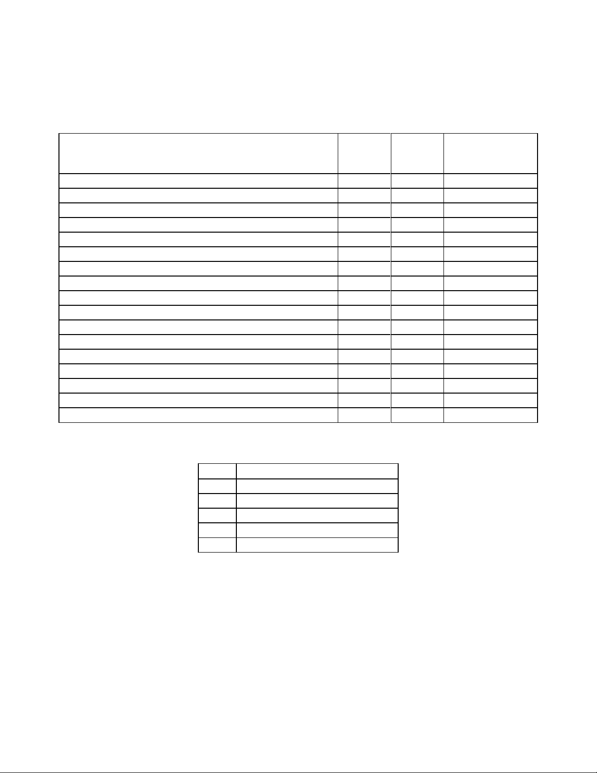
Table 1 below lists the IEEE 802.3af class, allocated power, and measured power of the Avaya
Avaya Powered Device
802.3af
Class
Volts
Measured
Power (W) (Idle)
Avaya 1603 IP Telephone with PoE Splitter
2
48.1
4.0
Avaya 1603SW IP Telephone with PoE Splitter
2
48.1
4.0
Avaya 1608 IP Telephone
2
48.1
4.0
Avaya 1616 IP Telephone
2
48.1
2.8
Avaya 1616 IP Telephone with BM32 Button Module
2
48.1
3.4
Avaya 9601 IP Telephone
1
48.1
1.9
Avaya 9608 IP Telephone
1
48.1
2.5
Avaya 9611G IP Telephone
1
48.1
2.5
Avaya 9620L IP Telephone
1
48.1
2.1
Avaya 9620C IP Telephone
2
48.1
4.0
Avaya 9621G IP Telephone
2
48.1
2.6
Avaya 9630G IP Telephone
2
48.1
3.8
Avaya 9640G IP Telephone
2
48.1
3.9
Avaya 9641G IP Telephone
2
48.1
2.7
Avaya 9641G IP Telephone with SMB24 Button Module
2
48.1
3.2
Avaya 9650C IP Telephone
2
48.1
4.0
Avaya 9670C IP Telephone
2
48.1
4.8
Class
PSE Output Max. Power (W)
0
15.4
1
4.0
2
7.0
3
15.4
4
Treat as Class 0
IP Telephones when connected to the 8500-G48T-e module. The power listed as measured by
the Extreme Networks BD8810 switch is for an idle phone. Cable length and impedance affects
power usage, so the measurements listed here may vary based on the cable used.
Table 2 below summarizes the IEEE 802.3af classes.
Page 5

TMA; Reviewed:
SPOC 6/21/2011
Solution & Interoperability Test Lab Application Notes
©2011 Avaya Inc. All Rights Reserved.
5 of 11
EXTR8500G48TPoE
2.3. Support
For technical support on Extreme Networks products, consult the support pages at
http://www.extremenetworks.com or contact the Extreme Networks at: 800-998-2408.
3. Reference Configuration
Figure 1 illustrates the configuration used in these Application Notes. All Avaya 16xx and 96xx
series telephones are registered with Avaya Aura® Communication Manager (H.323) or Avaya
Aura® Session Manager (SIP)
Figure 1 is for illustration purpose only and not all Avaya IP Telephones were simultaneously
powered on during testing.
Figure 1: PoE sample network configuration
Page 6

TMA; Reviewed:
SPOC 6/21/2011
Solution & Interoperability Test Lab Application Notes
©2011 Avaya Inc. All Rights Reserved.
6 of 11
EXTR8500G48TPoE
4. Equipment and Software Validated
Equipment
Software/Firmware
Avaya S8300D Server running Avaya Aura®
Communication Manager
Avaya Aura® Communication Manager 6.1
Avaya G450 Media Gateway
MGP
MM712 DCP Media Module
30 .13 .2
HW9
Avaya S8800 Server
Avaya Aura® Session Manager (6.1)
Avaya S8800 Server
Avaya Aura® System Manager (6.1)
Avaya 1603 IP Telephone with PoE Splitter
Avaya one-X™ Deskphone Value Edition H.323 (1.3)
Avaya 1603SW IP Telephone with PoE
Splitter
Avaya one-X™ Deskphone Value Edition H.323 (1.3)
Avaya 1608 IP Telephone
Avaya one-X™ Deskphone Value Edition H.323 (1.3)
Avaya 1616 IP Telephone with/without
BM32 Button Module
Avaya one-X™ Deskphone Value Edition 1.3 (H.323)
Avaya 9601 IP Telephone
Avaya one-X® Deskphone SIP (6.1)
Avaya 9608 IP Telephone
Avaya one-X® Deskphone SIP (6.1)
Avaya 9611G IP Telephone
Avaya one-X® Deskphone SIP (6.1)
Avaya 9620L IP Telephone
Avaya one-X™ Deskphone Edition H.323 (3.1.1)
Avaya 9620C IP Telephone
Avaya one-X™ Deskphone Edition H.323 (3.1.1)
Avaya 9621G IP Telephone
Avaya one-X® Deskphone SIP (6.1)
Avaya 9630G IP Telephone
Avaya one-X® Deskphone SIP (2.6)
Avaya 9640G IP Telephone
Avaya one-X® Deskphone SIP (2.6)
Avaya 9641G IP Telephone with/without
SMB24 Button Module
Avaya one-X® Deskphone SIP (6.1)
Avaya 9650C IP Telephone
Avaya one-X® Deskphone SIP (2.6)
Avaya 9670C IP Telephone
Avaya one-X® Deskphone SIP (2.6)
Extreme Networks BlackDiamond 8500
G48T-e 48-port 10/100/1000BASE-T RJ-45
with optional PoE
ExtremeXOS 12.1.5.6
BlackDiamond 8810
ExtremeXOS 12.1.5.6
The following equipment and software/firmware were used for the sample configuration
provided:
Page 7

TMA; Reviewed:
SPOC 6/21/2011
Solution & Interoperability Test Lab Application Notes
©2011 Avaya Inc. All Rights Reserved.
7 of 11
EXTR8500G48TPoE
5. Configure Avaya Telephony Equipment
Connect to the Extreme BlackDiamond 8810. Log in using the appropriate Login ID and
Password.
Login:
Password:
BD-8810.1#
BD-8810.2# configure vlan <VLAN NAME> delete ports <port>
BD-8810.3# create vlan vlan100
BD-8810.4# configure vlan100 ipaddress 10.32.100.254/24
BD-8810.5# enable ipforwarding vlan100
BD-8810.6# configure vlan100 add ports all
There is no configuration requirement on Avaya Aura® Communication Manager, Avaya Aura®
Session Manager or Avaya IP telephones to use the 8500 G48T-e 48 PoE module. It is assumed
that all Aura® Telephony components, appropriate licenses and authentication files have been
configured already, e.g., trunks, dial plans, etc, and will not be covered in this document. For
detailed information on the installation, maintenance, and configuration of Communication
Manager and Session Manager, please reference [1], [2], and [3].
6. Configure BlackDiamond 8810 Chassis
This section shows the necessary steps in configuring the 8500-G48T-e module installed in the
BlackDiamond 8810 chassis as shown in the Figure 1.
Install the BD 8800 S-POE power module onto the 8500-G48T-e. Insert the 8500-G48T-e back
into the BD 8810 chassis. In-line power is enabled by default; the configuration of the VLANs
and ports required to support the environment in Figure 1 are shown below:
1. Log into the Extreme BlackDiamond 8810 Switch.
2. If any of the ports are configured with VLAN information use the configure vlan <VLAN
NAME> delete ports <port> command to delete it.
3. Create VLAN 100 and add ports to the VLAN.
Page 8

TMA; Reviewed:
SPOC 6/21/2011
Solution & Interoperability Test Lab Application Notes
©2011 Avaya Inc. All Rights Reserved.
8 of 11
EXTR8500G48TPoE
7. Verification Steps
BD-8810.5 # show inline-power
Inline Power System Information
Configured : Enabled
System Power Surplus : 1164 Watts available for budgeting
Redundant Power Surplus : 600 Watts available for budgeting to maintain N+1
Power Usage Threshold : 70 percent (per slot)
Disconnect Precedence : deny-port
Budgeted Measured
Slot Inline-Power Firmware Status Power (Watts) Power (Watts) Legacy
7 Enabled Operational 50 W 0 W Disabled
BD-8810.6 # show inline-power stat slot 7
Inline-Power Slot Statistics
Slot: 7
Firmware status : Operational
Firmware revision : 605b2
Total ports powered : 0
Total ports awaiting power : 48
Total ports faulted : 0
Total ports disabled : 0
Inline Power over Ethernet (PoE) is supported on the Extreme Networks 8500-G48T-e module.
By default, PoE support is enabled on the system and on all ports.
Use the “show inline-power” command to verify available power available on the switch.
Use the “show inline-power stats slot <slot#>” command to display the PoE status of the
slot.
Page 9

TMA; Reviewed:
SPOC 6/21/2011
Solution & Interoperability Test Lab Application Notes
©2011 Avaya Inc. All Rights Reserved.
9 of 11
EXTR8500G48TPoE
Use the “show inline-power configuration port <port#>” command to verify available
BD-8810.7 # show inline-power configuration ports 7:4
Port Config Operator Limit Priority Label
7:4 Enabled 15400 mW Low
* BD-8810.10 # show inline-power info detail ports 7:4
Port 7:4
Configured Admin State: enabled
Inline Power State : delivering
MIB Detect Status : delivering
Label :
Operator Limit : 15400 milliwatts
PD Class : class2
Max Allowed Power : 15.400 W
Measured Power : 3.500 W
Line Voltage : 48.1 Volts
Current : 74 mA
Fault Status : None
Detailed Status : valid resistor detected, 802.3a
Priority : low
power available on the port.
Use the “show inline-power info detail port <port #>” command to display the PoE status
of the individual port.
8. Conclusion
These Application Notes describe the steps for configuring the Extreme Networks 8500-G48T-e
module to provide inline Power over Ethernet (PoE) to the Avaya 9600 and 1600 Series IP
Telephones.
Page 10

TMA; Reviewed:
SPOC 6/21/2011
Solution & Interoperability Test Lab Application Notes
©2011 Avaya Inc. All Rights Reserved.
10 of 11
EXTR8500G48TPoE
9. Additional References
Product documentation for Avaya products may be found at http://support.avaya.com
[1] Installing and Configuring Avaya Aura® Communication Manager, Doc ID 03-603558,
Release 6.0.1 December 2010
[2] Administering Avaya Aura™ Communication Manager, Release 6.0, Doc ID 03-300509 June
2010
[3] Installing and Configuring Avaya Aura® Session Manager, Doc ID 03-603473, Release 6.1
January 2011
[4] Administering Avaya Aura® Session Manager, Doc ID 03-603324, Release 6.1 November
2010
[5] Administering Avaya Aura® System Manager, Release 6.1 November 2010
[6] Installing and Upgrading Avaya Aura® System Manager, Release 6.1 November 2010
[7] Avaya one-X™ Deskphone SIP Administrator Guide, Release 6, Doc ID 16-603838
December 2010
[8] Avaya one-X™ Deskphone H.323 Administrator Guide Release, Doc ID 6.0 16-300698
August 2010
[9] Avaya one-X™ Deskphone Edition for 9600 Series IP Telephones Administrator Guide, Doc
ID 16-300698 Issue 7 November 2009
[10] Avaya one-X™ Deskphone SIP for 9600 Series IP Telephones Administrator Guide,
Release 2.6, Doc ID 16-601944
[11] Avaya 1600 Series IP Deskphones Administrator Guide, Release 1.3.x
Product documentation for Extreme Networks products may be found at
http://www.extremenetworks.com
[12] BlackDiamond 8800 Series Switches Hardware Installation Guide, Part number:100284-00
[13] ExtremeXOS® Command Reference Guide, Part number: 100376-00
Page 11

TMA; Reviewed:
SPOC 6/21/2011
Solution & Interoperability Test Lab Application Notes
©2011 Avaya Inc. All Rights Reserved.
11 of 11
EXTR8500G48TPoE
©2011 Avaya Inc. All Rights Reserved.
Avaya and the Avaya Logo are trademarks of Avaya Inc. All trademarks identified by ® and
™ are registered trademarks or trademarks, respectively, of Avaya Inc. All other trademarks
are the property of their respective owners. The information provided in these Application
Notes is subject to change without notice. The configurations, technical data, and
recommendations provided in these Application Notes are believed to be accurate and
dependable, but are presented without express or implied warranty. Users are responsible for
their application of any products specified in these Application Notes.
Please e-mail any questions or comments pertaining to these Application Notes along with the
full title name and filename, located in the lower right corner, directly to the Avaya
DevConnect Program at devconnect@avaya.com.
 Loading...