

Page 1

Title page
Nortel Communication Server 1000
IP Phone 1140E
User Guide
Page 2

Page 3

Revision history
January 2010
Standard 04.02. This document is up-issued to support Nortel
Communication Server 1000 Release 6.0 for UNIStim 4.0.
October 2009
Standard 04.01. Because of the similarity between
Communication Server 1000 Release 6.0 for UNIStim 4.0
features and Release 5.5 features, UNISt im 4.0 Release 6.0
documentation is also used for Release 5.
June 2009
Standard 03.02. This document is up-issued to support Nortel
Communications Server 1000 Release 6.0.
May 2009
Standard 03.01. This document is up-issued to support Nortel
Communications Server 1000 Release 6.0.
Revision history
January 2009
Standard 02.05. This document is up-issued to support Nortel
Communications Server 1000 Release 5.5 for UNIStim 3.0. This
document reflects changes in section Enabling USB Headset.
December 2008
Standard 02.04. This document is up-issued to support Nortel
Communications Server 1000 Release 5.5 for UNIStim 3.0. This
document reflects changes in sections Setting up a conference
call and Charging a call or charging a forced call.
April 2008
Standard 02.03. This document is up-issued to support Nortel
Communications Server 1000 Release 5.5 for UNIStim 3.0.
3
Page 4

Revision history
May 2007
Standard 01.01. This document is up-issued to support
CS 1000 Release 5.0. This document reflects the ne w document
number.
November 2006
Stan dard 5.00. This do cument is up- issued to reflect a n update to
Regulatory information.
June 2006
Standard 4.00. This document is issued to support
Nortel Communication Server 1000 Release 4.5 sof tware. Ad ded
support for new security features.
February 2006
Standard 3.00. This document is issued to support
Nortel Communication Server 1000 Release 4.5 software.
January 2006
Standard 2.00. This document is issued to support
Nortel Communication Server 1000 Release 4.5 software.
November 2005
Standard 1.00. This document is issued to support
Nortel Communication Server 1000 Release 4.5 software.
4
Page 5

Contents
About the Nortel IP Phone 1140E . . . . . . . . . . . . . . . . . . . . 11
Basic features . . . . . . . . . . . . . . . . . . . . . . . . . . . . . . . . . . . . . 11
Telephone controls . . . . . . . . . . . . . . . . . . . . . . . . . . . . . . . . . 13
Telephone display . . . . . . . . . . . . . . . . . . . . . . . . . . . . . . . . . 20
License Notification . . . . . . . . . . . . . . . . . . . . . . . . . . . . . . . . 20
Call features and Flexible Feature Codes . . . . . . . . . . . . . . . 21
Security features . . . . . . . . . . . . . . . . . . . . . . . . . . . . . . . . . . . 21
Using encrypted calling . . . . . . . . . . . . . . . . . . . . . . . . . . 21
Managing your Station Control Password (SCPW) . . . . . 21
Entering and editing text . . . . . . . . . . . . . . . . . . . . . . . . . . . 24
Entering text using the IP phone dialpad . . . . . . . . . . . . . . . . 24
Entering text using the USB keyboard . . . . . . . . . . . . . . . . . . 25
Editing text using the soft keys . . . . . . . . . . . . . . . . . . . . . . . . 25
Contents
Connecting the components . . . . . . . . . . . . . . . . . . . . . . . . 27
Before you begin . . . . . . . . . . . . . . . . . . . . . . . . . . . . . . . . . . 28
Connecting the components of the phone . . . . . . . . . . . . . . . 28
Virtual Private Network . . . . . . . . . . . . . . . . . . . . . . . . . . . . 34
Before you begin . . . . . . . . . . . . . . . . . . . . . . . . . . . . . . . . . . 34
Connecting your IP Phone . . . . . . . . . . . . . . . . . . . . . . . . . . . 35
QoS configuration recommendations . . . . . . . . . . . . . . . . 37
Installing and configuring VPN . . . . . . . . . . . . . . . . . . . . . . . . 38
Configuring Telephone Options . . . . . . . . . . . . . . . . . . . . . 53
Using the Telephone Options menu . . . . . . . . . . . . . . . . . . . . 54
Adjusting the volume . . . . . . . . . . . . . . . . . . . . . . . . . . . . 55
Adjusting the display screen contrast . . . . . . . . . . . . . . . . 56
5
Page 6

Contents
Selecting a language . . . . . . . . . . . . . . . . . . . . . . . . . . . . 57
Selecting date and time format . . . . . . . . . . . . . . . . . . . . 58
Accessing display diagnostics . . . . . . . . . . . . . . . . . . . . . 59
Choosing a local dialpad tone . . . . . . . . . . . . . . . . . . . . . 59
Viewing IP Phone information . . . . . . . . . . . . . . . . . . . . . 60
Diagnostics . . . . . . . . . . . . . . . . . . . . . . . . . . . . . . . . . . . . 61
Configuring call log options . . . . . . . . . . . . . . . . . . . . . . . 62
Choosing a ring type . . . . . . . . . . . . . . . . . . . . . . . . . . . . 66
Enabling or disabling Call Timer . . . . . . . . . . . . . . . . . . . 67
Enabling OnHook Default Path . . . . . . . . . . . . . . . . . . . . 68
Changing feature key labels . . . . . . . . . . . . . . . . . . . . . . . 68
Configuring the name display format . . . . . . . . . . . . . . . . 70
Configuring Live Dialpad . . . . . . . . . . . . . . . . . . . . . . . . . 71
Configuring Caller ID display order . . . . . . . . . . . . . . . . . 72
Configuring Normal mode indication . . . . . . . . . . . . . . . . 72
Configuring Local Menu options . . . . . . . . . . . . . . . . . . . . 74
Using the 1. Preferences submenu . . . . . . . . . . . . . . . . . . . . 76
Changing 1. Display Settings . . . . . . . . . . . . . . . . . . . . . . 76
Changing 2. Language . . . . . . . . . . . . . . . . . . . . . . . . . . . 77
Configuring 3. Headsets . . . . . . . . . . . . . . . . . . . . . . . . . . 78
Configuring 4. Bluetooth . . . . . . . . . . . . . . . . . . . . . . . . . . 85
Using the 2. Local Diagnostics submenu . . . . . . . . . . . . . . . . 97
1. IP Set&DHCP Information . . . . . . . . . . . . . . . . . . . . . . 97
2. Network Diagnostic Tools . . . . . . . . . . . . . . . . . . . . . . 97
3. Ethernet Statistics . . . . . . . . . . . . . . . . . . . . . . . . . . . . 97
4. IP Network Statistics . . . . . . . . . . . . . . . . . . . . . . . . . . 98
5. USB Devices . . . . . . . . . . . . . . . . . . . . . . . . . . . . . . . . 98
6. Advanced Diag Tools . . . . . . . . . . . . . . . . . . . . . . . . . . 98
7. DHCP Information . . . . . . . . . . . . . . . . . . . . . . . . . . . . 98
8. License Information . . . . . . . . . . . . . . . . . . . . . . . . . . . 98
9. VPN Information . . . . . . . . . . . . . . . . . . . . . . . . . . . . . . 99
10. Certificate Information . . . . . . . . . . . . . . . . . . . . . . . . 99
6
Page 7

Contents
Using the 3. Network Configuration menu . . . . . . . . . . . . . . . 99
Using the 4. Lock Menu . . . . . . . . . . . . . . . . . . . . . . . . . . . . 100
Making a call . . . . . . . . . . . . . . . . . . . . . . . . . . . . . . . . . . . . 101
Using Off-hook dialing . . . . . . . . . . . . . . . . . . . . . . . . . . . . . 101
Using On-hook dialing . . . . . . . . . . . . . . . . . . . . . . . . . . . . . 102
Using handsfree dialing . . . . . . . . . . . . . . . . . . . . . . . . . . . . 103
Using the Directory applications . . . . . . . . . . . . . . . . . . . . . . 105
Making a call using the Corporate Directory . . . . . . . . . 105
Making a call using the Personal Directory . . . . . . . . . . 106
Making a call using the Callers List . . . . . . . . . . . . . . . . 107
Making a call using the Redial List . . . . . . . . . . . . . . . . . 108
Using Predial . . . . . . . . . . . . . . . . . . . . . . . . . . . . . . . . . . . . 108
Using AutoDial . . . . . . . . . . . . . . . . . . . . . . . . . . . . . . . . . . . 109
Using Ring Again . . . . . . . . . . . . . . . . . . . . . . . . . . . . . . . . . 111
Using Last Number Redial . . . . . . . . . . . . . . . . . . . . . . . . . . 112
Using Speed Call . . . . . . . . . . . . . . . . . . . . . . . . . . . . . . . . . 113
Using System Speed Call . . . . . . . . . . . . . . . . . . . . . . . . . . . 114
Using HotLine . . . . . . . . . . . . . . . . . . . . . . . . . . . . . . . . . . . . 114
Using intercom calling . . . . . . . . . . . . . . . . . . . . . . . . . . . . . 115
Answering a call . . . . . . . . . . . . . . . . . . . . . . . . . . . . . . . . . 116
While on an active call . . . . . . . . . . . . . . . . . . . . . . . . . . . . 117
Placing a call on hold . . . . . . . . . . . . . . . . . . . . . . . . . . . . . . 117
Transferring a call . . . . . . . . . . . . . . . . . . . . . . . . . . . . . . . . . 118
Using Timed Reminder Recall . . . . . . . . . . . . . . . . . . . . . . . 119
Using Attendant Recall . . . . . . . . . . . . . . . . . . . . . . . . . . . . . 120
Using Call Park . . . . . . . . . . . . . . . . . . . . . . . . . . . . . . . . . . . 120
Recording a Calling Party Number . . . . . . . . . . . . . . . . . . . . 123
Displaying incoming calls . . . . . . . . . . . . . . . . . . . . . . . . . . . 123
7
Page 8

Contents
Tracing a malicious call . . . . . . . . . . . . . . . . . . . . . . . . . . . . 124
Incoming calls . . . . . . . . . . . . . . . . . . . . . . . . . . . . . . . . . . . 125
Using Automatic Answerback . . . . . . . . . . . . . . . . . . . . . . . . 125
Using Call Pickup . . . . . . . . . . . . . . . . . . . . . . . . . . . . . . . . . 125
Using Call Waiting . . . . . . . . . . . . . . . . . . . . . . . . . . . . . . . . 127
While away from your desk . . . . . . . . . . . . . . . . . . . . . . . . 129
Using Call Forward . . . . . . . . . . . . . . . . . . . . . . . . . . . . . . . . 129
Using Internal Call Forward . . . . . . . . . . . . . . . . . . . . . . . . . 130
Using Remote Call Forward . . . . . . . . . . . . . . . . . . . . . . . . . 131
Securing your IP Phone . . . . . . . . . . . . . . . . . . . . . . . . . . . . 133
Talking with more than one person . . . . . . . . . . . . . . . . . 135
Using the Call Join feature . . . . . . . . . . . . . . . . . . . . . . . . . . 135
Setting up a conference call . . . . . . . . . . . . . . . . . . . . . . . . . 135
Using Conferee Selectable Display . . . . . . . . . . . . . . . . . . . 137
Using Group Call . . . . . . . . . . . . . . . . . . . . . . . . . . . . . . . . . 138
Working without interruption . . . . . . . . . . . . . . . . . . . . . . 141
Using Make Set Busy . . . . . . . . . . . . . . . . . . . . . . . . . . . . . . 141
Additional call features . . . . . . . . . . . . . . . . . . . . . . . . . . . 142
Using AutoDial Transfer . . . . . . . . . . . . . . . . . . . . . . . . . . . . 142
Using the Buzz signal . . . . . . . . . . . . . . . . . . . . . . . . . . . . . . 143
Using Call Page Connect to make an announcement . . . . . 143
Using Centrex/Exchange Line Switchhook Flash . . . . . . . . . 144
Charging a call or charging a forced call . . . . . . . . . . . . . . . 145
Using Enhanced Override . . . . . . . . . . . . . . . . . . . . . . . . . . 148
Using Forced Camp-on feature . . . . . . . . . . . . . . . . . . . . . . 149
Overriding a busy signal . . . . . . . . . . . . . . . . . . . . . . . . . . . . 150
8
Page 9

Contents
Using Privacy Release . . . . . . . . . . . . . . . . . . . . . . . . . . . . . 151
Using Radio Page . . . . . . . . . . . . . . . . . . . . . . . . . . . . . . . . . 151
Using Voice Call . . . . . . . . . . . . . . . . . . . . . . . . . . . . . . . . . . 153
Additional phone features . . . . . . . . . . . . . . . . . . . . . . . . . 155
Using the Personal Directory . . . . . . . . . . . . . . . . . . . . . . . . 155
Using the Callers List . . . . . . . . . . . . . . . . . . . . . . . . . . . . . . 158
Using the Redial List . . . . . . . . . . . . . . . . . . . . . . . . . . . . . . . 160
Using Virtual Office . . . . . . . . . . . . . . . . . . . . . . . . . . . . . . . . 162
Logging in to Virtual Office . . . . . . . . . . . . . . . . . . . . . . . 163
Using Virtual Office on your Remote IP Phone . . . . . . . 164
Using Virtual Office on your Office IP Phone . . . . . . . . . 166
Logging out of Virtual Office . . . . . . . . . . . . . . . . . . . . . . 168
Troubleshooting Virtual Office . . . . . . . . . . . . . . . . . . . . 169
Using Media Gateway 1000B . . . . . . . . . . . . . . . . . . . . . . . . 171
Using Test Local Mode . . . . . . . . . . . . . . . . . . . . . . . . . 172
Using Resume Normal Mode . . . . . . . . . . . . . . . . . . . . . 172
Troubleshooting MG 1000B . . . . . . . . . . . . . . . . . . . . . . 173
Using Hospitality features . . . . . . . . . . . . . . . . . . . . . . . . . 174
Configuring Automatic Wake-Up . . . . . . . . . . . . . . . . . . . . . 174
Activating Message Registration . . . . . . . . . . . . . . . . . . . . . 176
Using Maid Identification . . . . . . . . . . . . . . . . . . . . . . . . . . . 177
Displaying Room Status . . . . . . . . . . . . . . . . . . . . . . . . . . . . 178
Accessing External Server Applications . . . . . . . . . . . . . 181
Flexible Feature Codes (FFCs) . . . . . . . . . . . . . . . . . . . . . 182
Regulatory and safety information . . . . . . . . . . . . . . . . . . 183
Other . . . . . . . . . . . . . . . . . . . . . . . . . . . . . . . . . . . . . . . . . . . 186
DenAn regulatory notice for Japan . . . . . . . . . . . . . . . . . . . . 187
9
Page 10

Contents
Terms you should know . . . . . . . . . . . . . . . . . . . . . . . . . . 189
Index . . . . . . . . . . . . . . . . . . . . . . . . . . . . . . . . . . . . . . . . . . 193
10
Page 11

Regulatory and safety information
Regulatory and safety
information
This equipment has been tested and found to comply with the limits for a
Class B digital device, pursuant to part 15 of the FCC Rules. These limits
are designed to provide reasonable protection against harmful
interference in a residential installation. This equipment generates, uses
and can radiate radio frequency energy and, if not installed and used in
accordance with the instructions, may cause harmful interference to radio
communications. However, there is no guarantee that interference will not
occur in a particular installation. If this equipment does cause harmful
interference to radio or television reception, which can be determined by
turning the equipment off and on, the user is encouraged to try to correct
the interference by one or more of the following measures:
• Reorient or relocate the receiving antenna .
• Increase the separation between the equipment and receiver.
• Connect the equipment into an outlet on a circuit different fr om that to
which the receiver is connected.
• Consult the dealer or an experienced radio/ TV technician for help.
Note: The user should not make changes or modifications not
expressly approved by Nortel Networks. Any such changes could
void the user’s authority to operate the equipment
This Class B digital apparatus complies with Canadian ICES-003. Cet
appareil numérique de la classe B est conforme à la norme NMB-003 du
Canada.
Warnings:
• This is a Class B product. In a domestic environment this product can
cause radio interference in which case the user must take adequate
measures.
• Operation is subject to the following two conditions: (1) this device
may not cause interference, and (2) this device mus t acce p t any
interference, including interference that may cause undesired
operation of the device."
• Privacy of communications may not be ensured when using this
IP Phone.
11
Page 12

Regulatory and safety information
• This equipment complies with FCC radiation exposure limits set forth
for an uncontrolled environment. This equipment should be installed
and operated with a minimum distance of 20cm between the radiator
and your body (excluding the handset). This transmitter must not be
colocated or operated in conjunction with any other antenna or
transmitter.
To prevent radio interference to the licensed service, this device must be
operated indoors only and should be kept away from windows to provide
maximum shielding.
この装置は、情報処理装置等電波障害自主規制協議会(VCCI)の基準に基づくクラス
B情報技術装置です。この装置は、家庭環境で使用することを目的としていますが、この
装置がラジオやテレビジョン受信機に近接して使用されると、受信障害を引き起こすこと
があります。
取扱説明書に従って正しい取り扱いをして下さい。
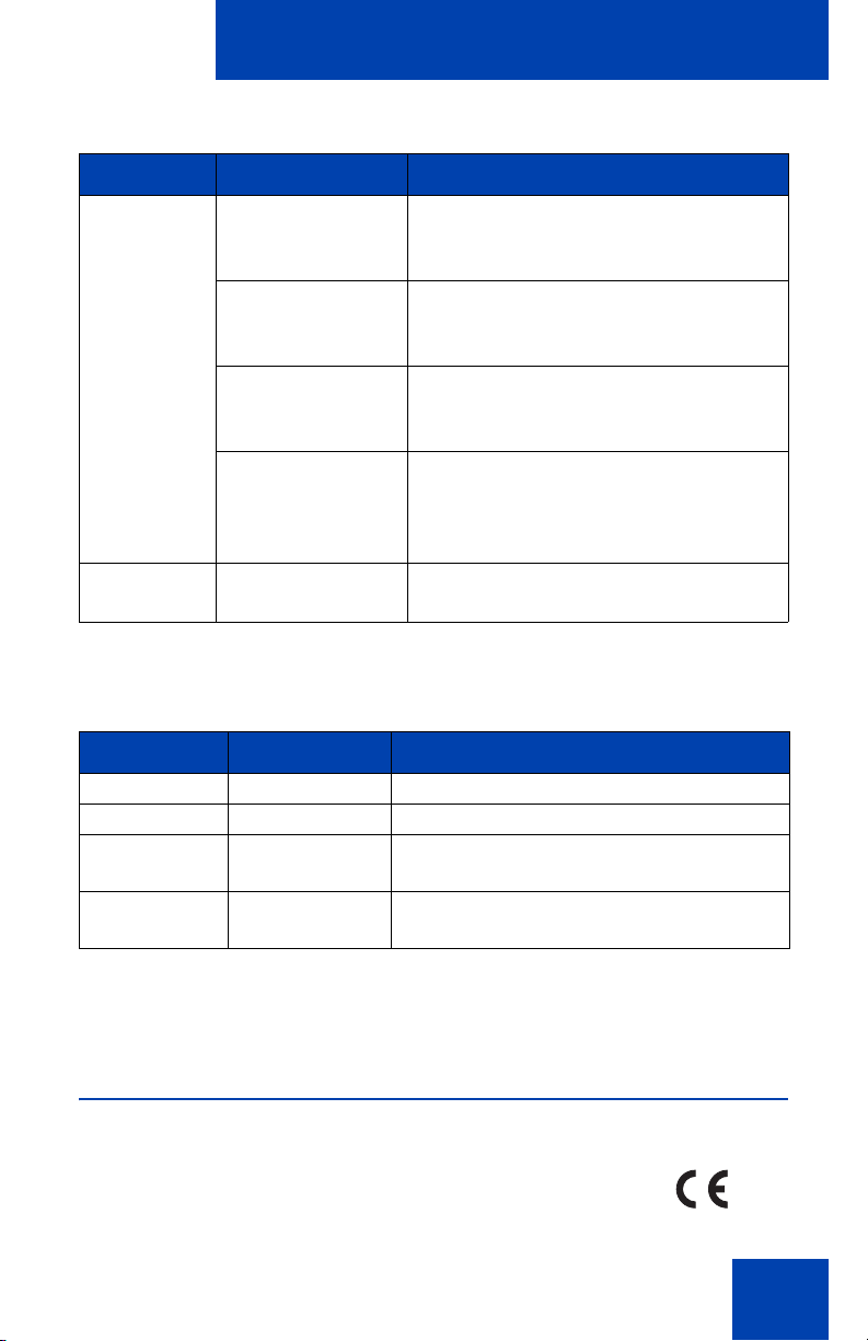
Table 1 lists EMC compliance for various jurisdictions.
Table 1: EMC compliance (Part 1 of 2)
Jurisdiction Standard Description
United
States
FCC CFR 47 Part 15Class B Emissions: FCC Rules for
Radio Frequency Devices (see Notes
1 and 2)
Canada ICES-003 Class B Emissions: Interference-
Causing Equipment Standard: Digital
Apparatus
Australia/
New
Zealand
AS/NZS 3548
CISPR 22
Class B Emissions: Information
technology equipment - Radio
disturbance
12
Page 13
Regulatory and safety information
Table 1: EMC compliance (Part 2 of 2)
Jurisdiction Standard Description
European
Community
EN 55022 Class B Emissions: Information
technology equipment - Radio
disturbance
EN 55024 Information technology equipment -
Immunity characteristics
Limits and methods of measurement
EN 61000-3-2 Limits for harmonic current emissions
(equipment input current <= 16 A per
phase)
EN 61000-3-3 Limitation of voltage fluctuations and
flicker in low-voltage supply systems
for equipment with rated current <= 16
A
Japan VCCI Regulations for voluntary control
measures.
Table 2 lists Safety compliance for various jurisdictions.
Table 2: Safety compliance
Jurisdiction Standard Description
United States UL 60950-1 Safety of Information T echnology Equipment
Canada CSA 60950-1-03 Safety of Information T echnology Equipment
European
Community
Australia/New
Zealand
EN 60950-1 ITE equipment - Safety - Part 1: General
requirements
AS/NZS
60950.1:2003
Safety of Information T echnology Equipment
Other Safety Approvals: IEC 60950-1: ITE equipment - Safety - Part 1:
General requirements.
Other
US/Canada: Hearing Aid Compatibility (HAC) as per FCC Part 68
This equipment complies with the CE Marking requirements.
13
Page 14
Regulatory and safety information
EU Countries: This device complies with the essential requirements and
other relevant provisions of Directive 1999/5/EC. A copy of the
Declaration may be obtained from www.nortel.com or Nortel Networks
GmbH address: Ingolstaedter Strasse 14-18, 80807 Munich Germany
Australia: AS/ACIF S004: Voice Frequency Performance Requirements
for Customer Equipment
Bluetooth wireless technology: This portable device with its antenna
complies with FCCs RF radiation exposure limits for an uncontrolled
environment. To maintain compliance, this transmittter must not be
cololcated or operate in conjunction with any oth er ante nna or tra nsmitter.
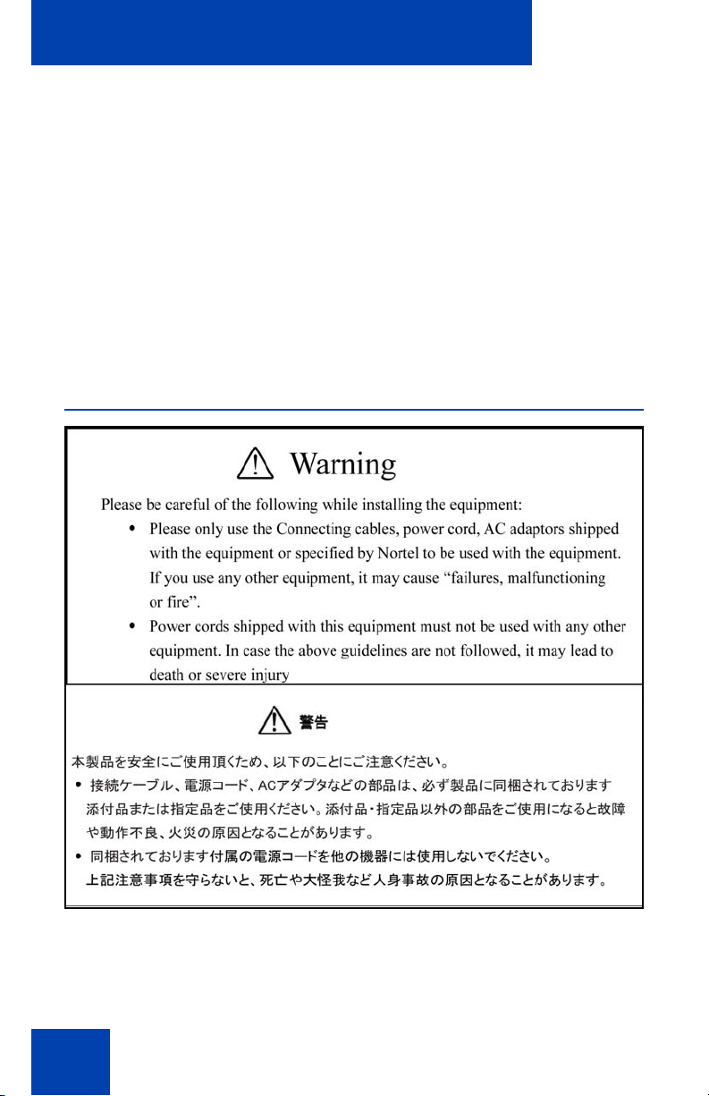
DenAn regulatory notice for Japan
14
Page 15

How to get Help
How to get Help
This section explains how to get help for Nortel products and services.
Getting Help from the Nortel Web site
The best way to get technical support for Nortel products is from the
Nortel Technical Support Web site:
http://www.nortel.com/support
This site provides quick access to software, documentation, bulletins, and
tools to address issues with Nortel products. More sp ec ifica lly, th e site
enables you to:
• download software, documentation, and product bulletins
• search the Technical Support Web site and the Nortel Knowledge
Base for answers to technical issues
• sign up for automatic notification of new software and documentatio n
for Nortel equipment
• open and manage technical support cases
Getting Help over the phone from a Nortel Solutions Center
If you don’t find the information you require on the Nortel Technical
Support Web site, and have a Nortel support contract, you can also get
help over the phone from a Nortel Solutions Center.
In North America, call 1-800-4NORTEL (1-800-466-7835).
Outside North America, go to the following Web site to obtain the phone
number for your region:
http://www.nortel.com/callus
Getting Help from a specialist by using an Express Routing Code
To access some Nortel Technical Solutions Centers, you can use an
Express Routing Code (ERC) to quickly route your call to a specialist in
15
Page 16

How to get Help
your Nortel product or service. To locate the ERC for your product or
service, go to:
http://www.nortel.com/erc
Getting Help through a Nortel distributor or reseller
If you purchased a service contract for your Nortel product from a
distributor or authorized reseller, contact the technical support staff for
that distributor or reseller.
16
Page 17

About the Nortel IP Phone 1140E
About the Nortel IP Phone 1140E
Your Nortel IP Phone 1140E brings voice and data to the desktop by
connecting directly to a Local Area Network (LAN) thro ug h an Ethe r ne t
connection.
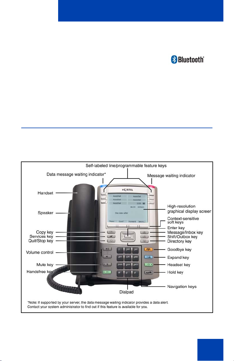
In this guide, self-labeled line/programmable feature key labels appear
beside the keys, and context-sensitive soft key labels appear directly
above the keys. Figure 1 shows self-labeled line/programmable feature
keys and context-sensitive soft keys.
Figure 1: Self-labeled line/programmable feature keys and
context-sensitive soft keys
Basic features
Your IP Phone 1140E supports the following features:
• six self-labeled line/programmable feature keys with labels and
indicators
• four context-sensitive soft keys
For information about context-sensitive soft keys, see Features and
Services Fundamentals (NN43001-106).
17
Page 18

About the Nortel IP Phone 1140E
Note: Some IP Phone 1140E phones are not configured to support
soft key functionality. Consult your system administrator.
• graphical, high-resolution LCD display, backlit, with adjustable
contrast
• high-quality speaker phone
• volume control keys for adjusting ringer, speaker, handset, and
headset volume
• six specialized feature keys:
—Quit
— Directory
— Message/Inbox
— Shift/Outbox
— Services
—Copy
• six call-processing fixed keys:
—Mute
— Handsfree
— Goodbye
— Expand
— Headset
—Hold
• gigabit Ethernet ports
• built-in gigabit Ethernet switch for shared PC access
• headset jack with an On/Off key
• USB port to support a keyboard, mouse, wireless headset, or an
audio device. The USB audio devices include the Nortel Enhanced
USB Headset Adapter, the Nortel Mobile USB Headset Adapter, the
Algo 4900 USB Analog Terminal Adapter (ATA), and wireless
headsets from GN Netcom and Plantronics. Powered downstream
1.1-compliant USB hubs are supported, including USB 2.0 hubs, if
they offer USB 1.1 backwards compliancy.
• automatic network configuration
18
Page 19
About the Nortel IP Phone 1140E
• Graphical XAS
• hearing aid compatibility
• wireless headset support using a Bluetooth® 1.2
wireless technology compliant Audio Gateway
(Headset Profile, Bluetooth Power Class 2).
• Accessory Expansion Module port to connect the Expansion Module
for IP Phone 1100 Series (Expansion Module)
For information about using the Expansion Module, see the Expansion
Module for IP Phone 1100 Series User Guide (NN43130-101).
Telephone controls
Figure 2 shows the IP Phone 1140E.
Figure 2: IP Phone 1140E
19
Page 20
About the Nortel IP Phone 1140E
Z
This section describes the controls on your IP Phone 1140E. In some
geographic regions, the IP Phone 1140E is offered with key caps that
have English text labels. In this document, text in parentheses indicates
the labels that appear on the key caps, for example, (Services).
Context-sensitive soft keys are located
below the display area. The LCD label above
each key changes based on the active
feature.
When a triangle appears before a soft key
label, the feature is active.
Press the More key to access the next layer
of context-sensitive soft keys (self-labeled).
The keys on either side of the LCD display
area are self-labeled line/programmable
feature keys, with labels on the LCD. These
keys also function as line (DN) keys.
20
A steady LCD light beside a line (DN) key
indicates that the line is active. A flashing
LCD light indicates the line is on hold or the
feature is being programmed.
A steady LCD light beside a feature key
indicates that the feature is active. A flashing
LCD light indicates that the feature is being
programmed.
Page 21
About the Nortel IP Phone 1140E
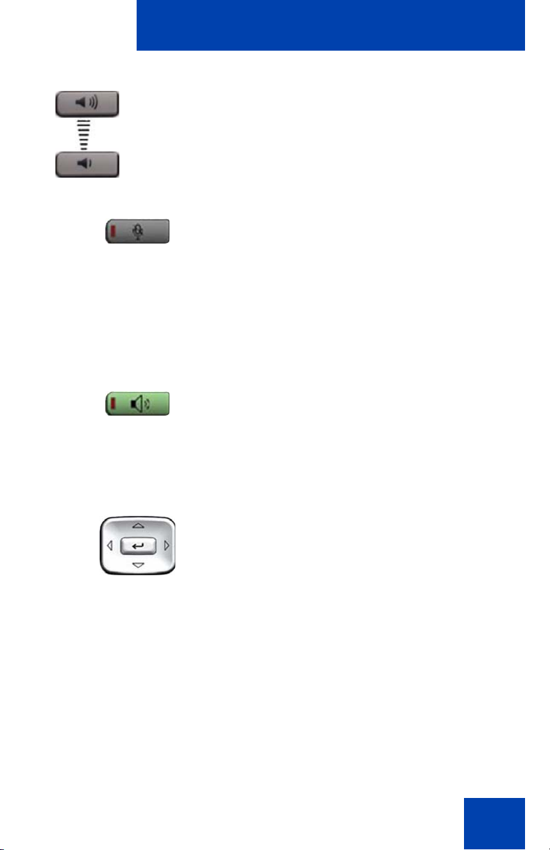
(Volume +)
(Volume -)
(Mute)
(Handsfree)
Use the Volume control buttons to adjust
the volume of the ringer, handset, headset,
speaker, and the Handsfree feature. Press
the top button to increase the volume, and
press the bottom button to decrease the
volume.
Press the Mute key to listen to the receiving
party without transmitting. Press the Mute
key again to return to two-way conversation.
The Mute key a pplies to handsfree, handset,
and headset microphones.
The Mute LED indicator, located on the Mute
key, flashes to indicate that the microphone
is muted.
Press the Handsfree key to activate
handsfree.
The Handsfree LED indicator, located on the
Handsfree key, lights to indicate when
handsfree is active.
Use the Navigation keys to scroll through
menus and lists appearing on the LCD
display screen. The outer part of this key
cluster rocks for up, down, left, and right
movements.
Use Up and Down to scroll up and down in
lists, and the Left and Right keys to position
the cursor. In some dialog boxes that app ear
on your phone, you can also use the Left
and Right keys to select editable fields;
press the Right key to select the field below
the current selection, or the Left key to
select the one above.
21
Page 22
About the Nortel IP Phone 1140E
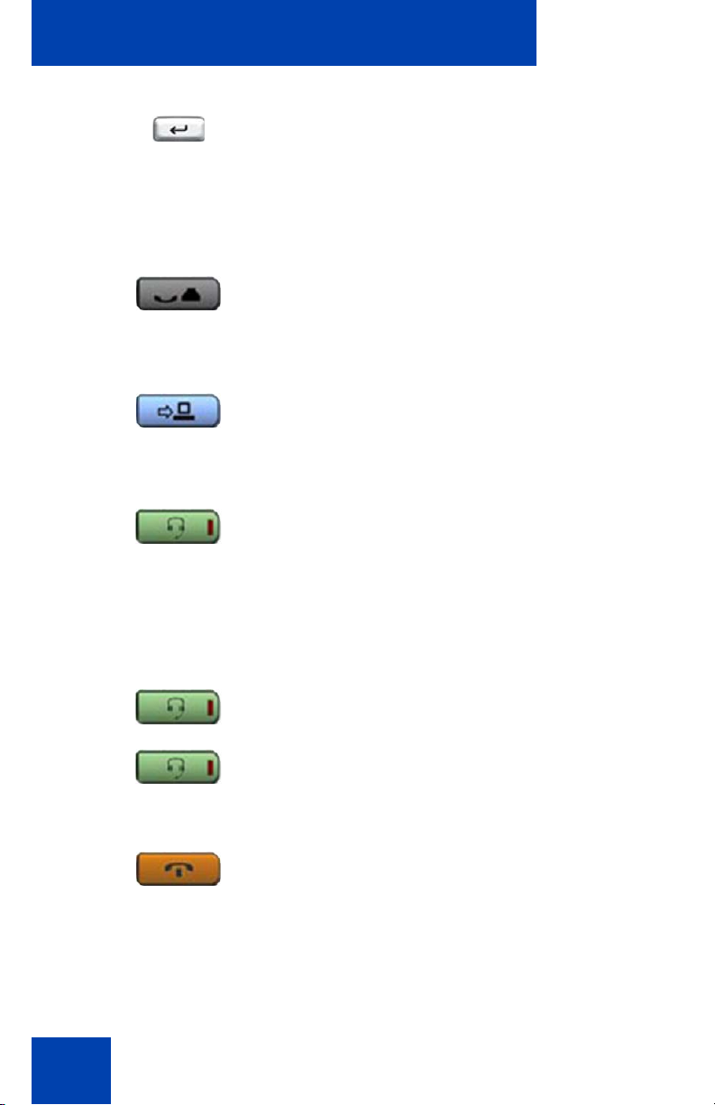
(Hold)
(Expand)
(Headset)
(Headset)
(Headset)
(Goodbye)
Use the Enter key, at the center of the
Navigation key cluster, to confirm menu
selections.
In most menus, you can use the Enter key
instead of the Select soft key.
Press the Hold key to put an active call on
hold. Tap the flashing line (DN) soft key to
return to the caller on hold.
Use the Expand key to access external
server applications
Press the Headset key to answer a call
using the headset or to switch a call from the
handset or handsfree to the headset.
22
The Headset LED indicator, located on the
Headset key, lights to indicate that the
headset is in use.
Press the Headset key twice to open the
Bluetooth Setup menu.
If Bluetooth wireless technology is not
enabled on your phone, this menu is not
available.
Use the Goodbye key to terminate an active
call.
Page 23
About the Nortel IP Phone 1140E
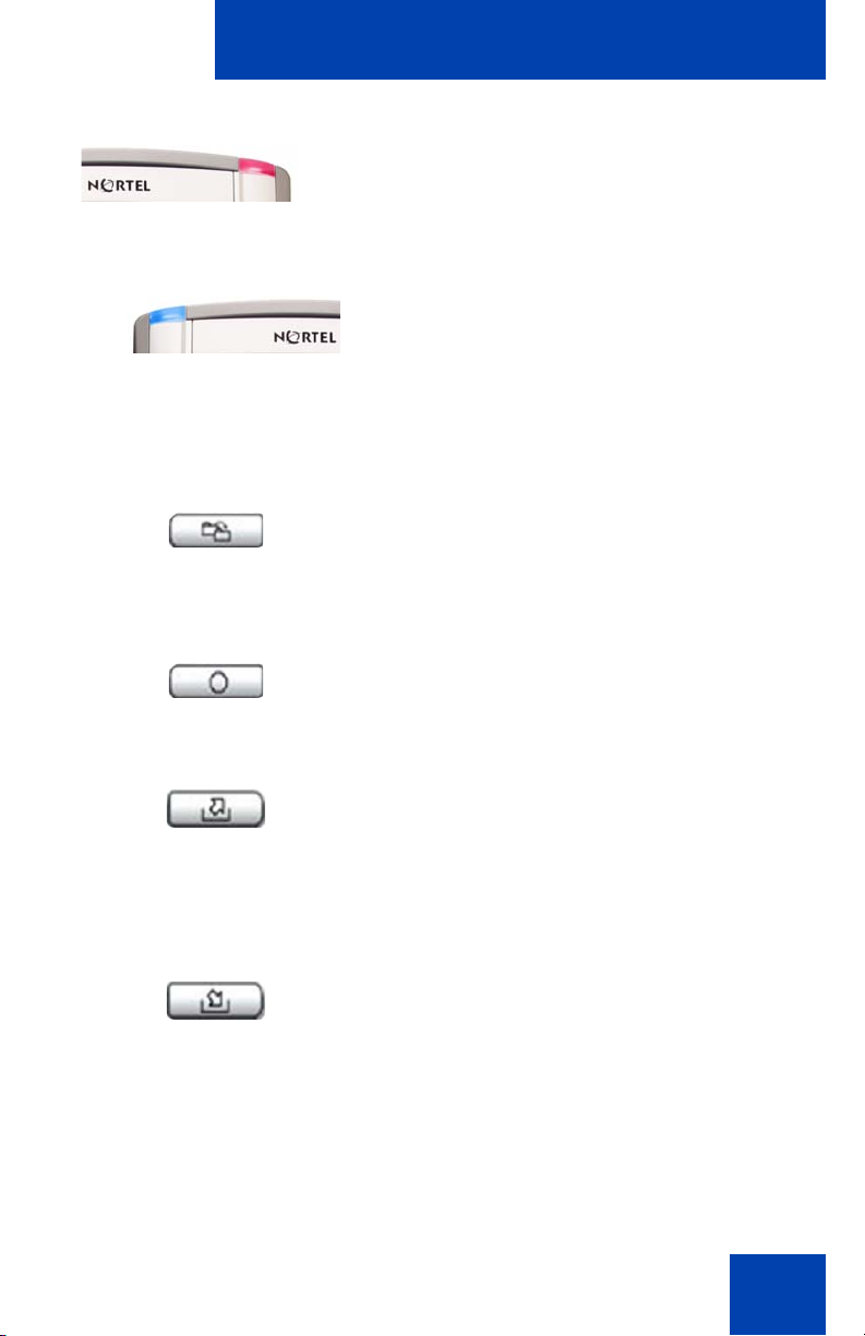
(Copy)
(Quit)
(Shift/Outbox)
(Msg/Inbox)
When a message is waiting, the red Visual
Alerter/Message Waiting indicator lights.
Also, when the ringer sounds, this indicator
flashes.
When your IP Phone 1140E firmware is
being updated, the blue Feature Status
Lamp indicator flashes.
To find out if additional features are
supported for this lamp, contact your
administrator.
Press the Copy Key to copy entries to your
Personal Directory from other lists, such as
the Caller List, Redial List, and Corporate
Directory.
Press the Quit/Stop key to exit an active
menu or dialog. Pressing the Quit/Stop key
does not affect the status of active calls.
Press the Shift/Outbox key to toggle
between two feature key pages and to
access an additional six lines/features.
This function is not available on all phones;
consult your system administrator.
Press the Message/Inbox key to access
your voice mailbox.
This function is not available on all phones;
consult your system administrator.
23
Page 24

About the Nortel IP Phone 1140E
(Directory)
(Services)
Press the Directory key to access directory
services.
Press the Services key and use the
navigation keys to access the following
items:
• Telephone Options:
— Volume adjustment
— Contrast adjustment
— Language
— Date/Time
— Display diagnostics
— Local Dialpad Tone
— Set Info
— Diagnostics
— Call Log Options
— Ring type
— Call Timer
— On hook default path
— Change Feature Key Label
— Name Display Format
— Live Dialpad
24
— Caller ID display order
— Normal mode indication
Page 25

(continued)
(Services)
(Services)
(Services)
About the Nortel IP Phone 1140E
• Password Admin:
— Station Control Password
The Password Admin menu is not
available on all IP Phone 1140E phones.
Consult your system administrator.
• Display Network Diagnostics Utilities
Only your system administrator
or service provider can use Display
Network Diagnostics Utilities to perform
Internet diagnostics.
• Virtual Office Login and Virtual Office
Logout (if Virtual Office is configured)
• Test Local Mode and Resume Local
Mode (if Media Gateway 1000B is
configured)
Press the Services key to exit from any
menu or menu item.
Press the Services key twice to access the
Local Tools menu, and use the navigation
keys to access the following items:
• 1. Preferences
• 2. Local Diagnostics
• 3. Network Configuration
•4. Lock Menu
If you attempt to access the Local Tools
menu and a dialog box appears
prompting you for a password, contact
your system administrator. Your system
administrator can establish a password
for the Local Tools menu.
25
Page 26
About the Nortel IP Phone 1140E
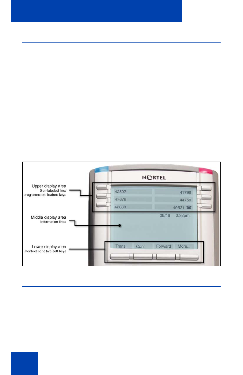
Telephone display
Your IP Phone 1140E has three display areas:
• The upper display area provides labels for the six self-labeled line/
programmable feature key labels.
• The middle display area contains single-line information for items
such as caller number, caller name, Call Timer, feature prompt
strings, user-entered digits, date and time information, and IP Phone
information.
• The lower display area provides labels for the four context-sensitive
soft keys.
Figure 3 shows an idle LCD screen.
Figure 3: IP Phone 1140E LCD screen
License Notification
Notify your system administrator if your phone displays a message in a
pop-up window about the licensing feature or evaluation period. License
notification provides details to help diagnose why the features are
disabled on the phone. You can press the Stop key or lift the handset to
close the window. The window redisplays every 24 hours at 1:00 AM
(default). The time and time frame can be configured when you provision
26
Page 27

About the Nortel IP Phone 1140E
the phone. For information about provisioning the IP Phones, see Nortel
Communication Server 1000 IP Phones Fundamentals (NN43001-368).
Call features and Flexible Feature Codes
Some features are not available on all IP Phones. Call features and
Flexible Feature Codes (FFC) must be assigned to your IP Phone and
supported by system software. Contact your system administrator to
configure these features and codes on your IP Phone.
Security features
The following security features are available on your IP Phone 1140E:
• Using encrypted calling
• Managing your Station Control Password (SCPW)
Using encrypted calling
Your IP Phone 1140E supports secure communication using SRTP
media encryption. If the feature is enabled, a security icon ( q) appears on
the screen when your call is secured using SRTP media encryption.
Contact your system administrator to find out if this feature is available for
your use.
Managing your Station Control Password (SCPW)
Your Station Control Password (SCPW) enables the following security
features:
• Electronic Lock to prevent others from making calls from your IP
Phone
• password-protected IP Phone features (for example, Personal
Directory, Redial List, and Callers List)
Your system administrator defines your initial SCPW. Contact your
system administrator for detailed inform at ion .
27
Page 28
About the Nortel IP Phone 1140E
(Services)
To change your SCPW:
1. Press the Services key.
2. Press the Up/Down keys to scroll and
highlight Password Admin.
3. Press the Enter key.
4. Use the dialpad to enter your password
at the prompt.
5. Press the Up/Down keys to scroll and
highlight New Password.
6. Press the Enter key.
7. Use the dialpad to enter the new
password.
8. Press the Select soft key to accept the
new password.
If you are locked out of your
IP Phone 1140E, or if you forget your
SCPW, contact your system
administrator.
Note: The default configuration for Password Protection is off.
28
Page 29
About the Nortel IP Phone 1140E
(Directory)
or
To turn Password Protection on or off:
1. Press the Directory key.
2. Press the Up/Down navigation keys to
scroll and highlight Change Protection
Mode.
3. Use the dialpad to enter your password
(if Password Protection is enabled).
4. Press the Enter soft key.
5. Press the Up/Down navigation keys to
scroll and highlight one of the following:
— Enable Password Protection
— Disable Password Protection
6. Choose one of the following soft keys:
— Yes to accept the se lection
— No to return to the Directory menu
7. Press the Done soft key.
29
Page 30

Entering and editing text
Entering and editing text
You can enter and edit text on your IP Phone 1140E using the following
methods:
• “Entering text using the IP phone dialpad” on page 30
• “Entering text using the USB keyboard” on page 31
• “Editing text using the soft keys” on page 31
The use of any of these methods for text entry or editing depends on the
application. Table 3 shows the applications and input devices that you
can use for text entry.
Table 3: Application text entry
For: Use:
Call Server-related applications
(for example, changing feature
key labels, adding personal
directory entries, or dialing)
Graphical applications USB keyboard
Local Tools menu USB keyboard
Dialpad
USB keyboard for numeric
entries only
Dialpad for numeric entries
Entering text using the IP phone dialpad
You can use the dialpad to enter text when you use features such as
Personal Directory, Redial List, and Callers List. Use the dialpad in
conjunction with the soft keys.
For example, if you want to enter the letter A, press the number 2 key
once. If you want to enter the letter C, press the number 2 key three
times. No letters are associated with the number 1 or the 0 keys.
30
Page 31

Entering and editing text
Entering text using the USB keyboard
You can use the USB keyboard, when connected, to enter text in the tools
and graphical applications.
For number entry in phone applications (for example, when dialing), you
can use the keyboard to enter digits (0 to 9), as well as * and #. Other
characters are ignored.
When on a call, you can use the function keys (f1, f2, f3, f4, f5, f6, f7, and
f8) to control the IP Phone. Table 4 shows the function keys and their
associated action during IP Phone calls.
Table 4: USB keyboard function keys during IP Phone calls
Function key Action
f1 Go to Handsfree mode
f2 Go to Headset mode
f3 Place the current call on hold
f4 Mute the current call
f5 Volume up
f6 Volume down
f7 Copy
f8 Quit
Editing text using the soft keys
You can use soft keys to edit text when you use features such as
Personal Directory, Redial List, and Callers List. Use the soft keys in
conjunction with the dialpad.
31
Page 32

Entering and editing text
To edit an entry in your Personal Directory, press the Directory key, and
select the desired entry from your Personal Directory.
To edit text with the soft keys:
1. Press the Edit soft key.
2. Press the Left/Right navigation keys to move through the text.
3. Select the appropriate editing soft key for the operation you want to
perform.
4. If the character you want is not visible, press the More soft key to
access the next layer of soft keys.
5. To add non-alphanumeric symbols, press the Symbol soft key, and
perform the following:
a. Press the Up navigation key to access the symbols.
b. Press the Left/Right navigation keys to move to a specific
symbol.
c. Press the Choose soft key to select a symbol.
6. Press the Next soft key to submit your changes.
When you are editing text using the soft keys, various commands are
available on the soft keys to help you, as described in Table 5.
Table 5: Editing soft key description
Soft key Description
Cancel Cancel an action.
Choose Select a non-alphanumeric symbol (available
only after the Symbol soft key is selected).
Clear Clear the input field.
Case Switch the next character to either uppercase or
lowercase.
Delete Backspace one character.
Done/Select/Enter Varies, depending on the state of your phone.
More Access additional soft keys.
32
Page 33

Connecting the components
Connecting the components
Figure 4 shows connections on the IP Phone 1140E.
Figure 4: IP Phone 1140E connections
WARNING
Ensure that the protective rubber cap on the Accessory
Expansion Module port is in place when the port is not in
use. Connecting anything other than the proper
Expansion Module for IP Phone 1100 Series connector
to this port can cause damage to the IP Phone.
33
Page 34

Connecting the components
Before you begin
CAUTION
Damage to Equipment
Do not plug your IP Phone 1140E into a regular
phone jack. This results in severe damage to the
IP Phone. Consult your system administrator to
ensure that you plug your IP Phone into a 10/
100BaseT Ethernet jack.
CAUTION
Your IP Phone 1140E is designed for use in an
indoor environment only.
Connecting the components of the phone
WARNING
Your IP Phone 1140E is shipped with the base locked in
position. To avoid damaging your phone, press the wallmount lever, located just under the Handsfree key as
indicated in Figure 5 on page 35, to release the base
and pull it away from the phone.
34
Page 35

Connecting the components
Figure 5: Release the IP Phone 1140E from the stand
Use the following steps to connect the components of your phone.
1. Remove the stand cover. Pull upward on the center catch as
indicated in Figure 6 on page 36, and remove the stand cover. The
cable routing tracks are now accessible.
35
Page 36

Connecting the components
Figure 6: Remove the stand cover
2. Connect the global power supply (optional). Connect the global power
supply to the AC adapter jack in the bottom of the phone. Form a
small bend in the cable, and then thread the adapter cord through the
channels in the stand.
WARNING
Use your IP Phone 1140E with the approved global
power supply (model NTYS17BAE6).
Note 1: Your IP Phone 1140E supports both AC power and Power
over Ethernet options, including IEEE 802.3af stand ard power . To use
local AC power, th e optional global power supply can be ordered
separately. To use Power over Ethernet, where power is delivered
36
Page 37

Connecting the components
over the CAT5e cable, the LAN must support Power over Ethernet,
and a global power supply is not required.
Note 2: You must use CAT5e (or later) cables if you want to use
gigabit Ethernet.
3. Install the handset. Connect the end of the handset cable with the
short straight section into the handset. Connect the end of the
handset cable with the long straight section to the back of the phone,
using the RJ-9 handset jack marked with the symbol
bend in the cable, and then thread the handset cord through the
channels in the stand so that it exits behind the handset on the right
side, in the Handset cord exit in the stand base, as shown in Figure 7
on page 38.
4. Install the headset (optional). If you are installing a headset, plug the
connector into the RJ-9 headset jack on the back of the phone
marked with the symbol ), and thread the headset cord along with
the handset cord through the channels in the stand, so that the
headset cord exits the channel marked with the symbol ).
5. Install the Ethernet cable. Connect one end of the supplied Ethernet
cable to the back of your phone using the RJ-45 connector marked
with the symbol %, and thread the network cable through the channel
marked with the symbol %.
+. Form a small
6. If you are connecting your PC through the ph on e , you requir e a
second CAT5e cable. Only one cable is included with the
IP Phone 1140E package. Install the Ethernet cable connecting the
PC to the phone (optional). Connect one end of the PC Ethernet
cable to your phone using the RJ-45 connector marked with the
symbol ( and thread it through the channel mark ed with th e sy mbo l
(. Connect the other end to the LAN connector on the back of your
PC.
7. Install additional cables. If applicable, plug in optional USB devices.
Connect the Ethernet cable to the LAN Ethernet connection. If you
are using a global power supply, plug the global power supply into an
AC outlet.
37
Page 38

Connecting the components
Figure 7: Cable routing tracks and mounting holes
8. Wall-mount your phone (optional). Your IP Phone 1140E can be
mounted either by: (Method A) using the mounting holes on the
bottom of the phone stand, or (Method B) using a traditional-style
wall-mount box with RJ-45 connector and 15-cm (6-inch) RJ-45 cord
(not provided).
Complete steps 1-7, as needed, before you wall-mount your phone:
Method A: Press the wall-mount lever, and pull the phon e away from
the stand, as shown in Figure 5 on page 35. Using the stand cover
(the part you removed in step 1), mark the wall-mount holes by
pressing the bottom of the stand cover firmly against the wall in the
location where you wish to install the phone. Four small pins on the
bottom of the stand cover make marks on the wall. Use the marks as
a guideline for installing the wall-mount screws (not provided). Install
the screws so that they protrude 3 mm (1/8 inch) from the wall, and
then install the phone stand mounting holes over the screw heads.
You may need to remove the phone from the wall to adjust the lower
screws. When the lower screws are snug, install the phone on the
38
Page 39

Connecting the components
mounting screws, and then tighten the top screws. See Figure 7 on
page 38.
Method B: Attach the 15-cm (6-inch) CAT5e cable, position the stand
over the mounting rivets, and slide the phone down the wall so that
the rivets fit into the slots on the stand, indicated in Figure 7 on page
38 (Method B).
9. Replace the stand cover. Ensure that all cables are neatly routed and
press the stand cover into place until you hear a click.
10. Put the phone in the wall-mount position (optional). If you wallmounted your phone, put it in the wall-mount position by holding the
Tilt Lever and pressing the phone towards the base until the phon e is
parallel with the base. Release the Tilt Lever and continue to push the
phone towards the base until you hear an audible click. Ensure the
phone is securely locked in position.
39
Page 40

Virtual Private Network
Virtual Private Network
A Virtual Private Network (VPN) is a network that uses a public network
infrastructure, such as the Internet, to provide you with secure access to
the private network of your organization.
The IP Phone VPN feature allows you to connect to your organization’s
private network from a public or remote network. For example, you can
use your home public Internet connection to connect to your
organization’s private network.
This chapter describes the procedure to upgrade the software of your IP
Phone (if required) and configure the VPN on your IP Pho ne . An
installation wizard helps you perform the necessary steps.
Note: The INortel Phone VPN Configuration Wizard uses the default
language of the operating system of your PC. If the language is not
supported by the wizard, the default wizard language is English.
Your system administrator provides you with all the necessary files you
require to configure your IP Phone for VPN, and helps you to resolve any
errors that occur during configuration.
Before you begin
Before you upgrade the IP Phone software and configure VPN on your IP
Phone, complete the following checklist.
• Ensure that your PC is using one of the following operating systems:
— Windows XP
— Windows Vista
— Macintosh OS
• Ensure that you received a copy of the provisioning files from your
network administrator. The following files should be included:
— Nortel Phone VPN Configuration Wizard.jar
— provisioning files (for example: system.prv)
40
Page 41

Virtual Private Network
— .bin files (for example: 0625C7C.bin)
• Java Virtual Machine (JVM) version 1.5 or later must be installed on
your PC. Check Start, Settings, Control Panel, Java to see if JVM
is installed on your machine and the version of it. If it is not installed,
contact your system administration to help you to install it. To
download the latest JVM, go to www.java.com.
• Ensure that your PC has a firewall that allows incoming
communication to the following ports:
— UDP Port 69 (TFTP)
— TCP Port 80 (HTTP)
— UDP Port 4900 0
Note: The Nortel Phone VPN Configuration Wizard.jar file creates a
log.txt file during execution. This file is helpful to troubleshoot
problems you experience using the Nortel Phone VPN Configuration
Wizard.jar. The log.txt file is located in the same directory as
Nortel Phone VPN Configuration Wizard.jar.
Connecting your IP Phone
Before you connect your IP Phone to your PC, ensure that components
of your phone are connected properly. For more information about
connecting your IP Phone, see “Connecting the components” on page33.
Connect your IP Phone using one of the following methods:
• connect to your modem. See Figure 8 on page 42.
• connect to your router. See Figure 9 on page 42.
• connect to your wireless access point and modem. See Figure 10 on
page 43.
41
Page 42

Virtual Private Network
Figure 8: IP Phone connected to the modem
Figure 9: IP Phone connected to the router
42
Page 43

Virtual Private Network
Figure 10: IP Phone connected to the wireless access point
and modem
Note: If your home network is not configured as described in the
above figures, contact your system administrator for assistance.
Note: You cannot connect multiple PCs directly to the PC port on the
IP Phone.
Note: The Nortel Phone VPN Configuration Wizard requires direct
communication with the IP Phone on the network. Ensure that your
network allows devices to communicate with each other on the local
network. Some network equipment allows you to isolate devices from
each other . If you are unsu re, it is recommen ded that you tempo rarily
connect your PC to the IP Phone to run the initial Nortel Phone VPN
Configuration Wizard. See Figure 8 on page 42.
QoS configuration recommendations
Nortel recommends that you connect the PC to the IP Phones PC
Ethernet Port as the IP Phone provides Quality of Service (QoS) on
outbound traffic automatically.
If other PCs share the internet connection then Nortel recommends that
you configure QoS for outbound traffic and prioritize the IP Phone traffic.
Typical QoS methods that are available are port based priority, MAC
Address based Priority , and IP Address ba sed Priority. T o configure QoS,
see your router documentation.
43
Page 44

Virtual Private Network
Installing and configuring VPN
Use the following procedure to install and configure VPN on your IP
Phone.
Note: Depending on the version of software installed on your IP
Phone you may need to upgrade the software on the IP Phone prio r
to configuring the VPN feature.
To install and configure VPN
1. Follow the instructions provided by your system administrator to
obtain the required files.
2. Power-down the IP Phone.
3. Run the Nortel Phone VPN Configuration Wizard.jar file.
The Welcome & language select ion window of the Wizard ap pears,
as shown in Figure 11.
Figure 11: Welcome & language selection window
44
Page 45

4. Select your language preference.
The following languages are supported:
• Arabic
• Chinese - simplified
• Chinese - traditional
• Czech
•Danish
•Dutch
• English
•Finnish
•French
•German
•Greek
•Hebrew
• Hungarian
Virtual Private Network
• Italian
• Japanese - Katakana
• Japanese - Kanji
• Korean
•Latvian
• Norwegian
•Polish
• Portuguese
• Russian
• Spanish
•Swedish
• Turkish
5. Click Next.
45
Page 46

Virtual Private Network
The Equipment Setup and VPN window appears, as shown in
Figure 12.
Figure 12: Equipment Setup and VPN window
6. Verify that the modem, IP Phone, and PC are connected properly.
7. Disconnect any VPN connection currently running on your PC. See
Figure 4 on page 33 to confirm that your LAN Ethernet Port and PC
Ethernet Port on the IP Phone are connected corre ct ly.
Note: Connect the IP Phone LAN Ethernet port, marked with the %
symbol on the back of the phone to your network equipment only.
Connect only 1 PC (if applicable) to the PC Ethernet port, marked
with the ( symbol on the back of the phone.
Note: Optional: Click More to read a description of VPN.
8. Click Next.
The Locate Data Files window appears, as shown in Figure 13 on
page 47.
46
Page 47

Virtual Private Network
Figure 13: Locate Data Files window
9. Click Browse to locate the provisioning files provided by your system
administrator, if the wizard was not able to locate the files.
10. Click Next.
The Prepare Phone for Configuration window appears as sho wn in
Figure 14 on page 48.
47
Page 48

Virtual Private Network
Mute
Mute
Figure 14: Prepare Phone for Configuration window
11. Power on your IP Phone.
Note: Depending on the current software version on the IP Phone
“Listening Mode” may not be detected. If your phone does not enter
“Listening Mode”, follow the steps below.
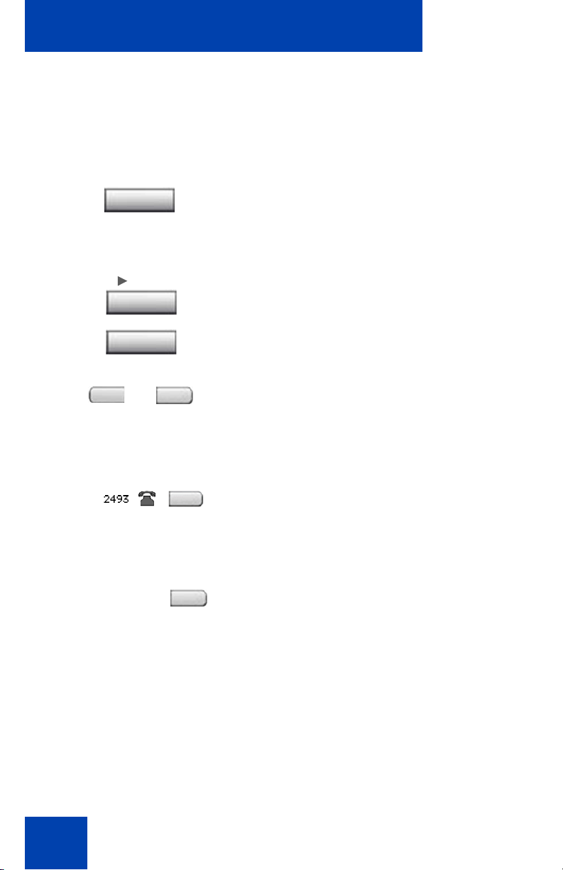
12. After you hear the chimes tune and the te xt NORTEL appears on the
IP Phone display screen, quickly press the following keys in order.
13. Verify that the IP Phone displays Listening Mode.
Note: The IP Phone can take up to 60 seconds for “Listening Mode”
to appear in the display area.
If the IP Phone displays Listening Mode, click Yes and go to Step 15
on page 53.
OR
If the IP Phone does not display Listening Mode, click No.
48
Page 49

Virtual Private Network
Mute
Mute
The Prepare Phone for Configuration (Try again) window appears,
as shown in Figure 15 on page 49.
Figure 15: Prepare Phone for Configuration (Try again)
window
a. Power off your IP Phone and power it back on again.
14. After you hear the chimes tune and the te xt NORTEL appears on the
IP Phone display screen, quickly press the following keys in order.
Note: The IP Phone can take up to 60 seconds for “Listening Mode”
to appear in the display area.
b. If the IP Phone displays Listening Mode, click Yes and go to
Step 15 on page 53.
OR
If the IP Phone does not display Listening Mode then your IP
Phone requires a software upgrade in order to proceed.
49
Page 50

Virtual Private Network
Click No to proceed to a software upgrade. Follow the next steps
to perform a software upgrade on your phone.
The Prepare Phone for Configuration window appears as
shown in Figure 16.
Figure 16: Prepare Phone for Configuration window
c. Double-press the Services key on the IP Phone quickly.
Select the Network Configuration menu item.
Move the cursor to locate Provision: or (TFTP IP:) in the
Network Configuration menu, and then write down the existing
address of the provisioning server so you can revert to it after you
complete this procedure.
Note: If a password prompt dialog box appears, press Cancel. Wait
until your IP Phone display completes the “Starting DHCP…” screen
then perform Step c again.
For information about entering and editing text in the Local menu , see
“Entering and editing text” on page 30.
d. If you are able to navigate to the Provision: or (TFTP IP:)
parameter, and edit this field, click Yes.
50
Page 51

Virtual Private Network
The Prepare Phone for Configuration (Input Provisioning
Server IP address) window appears, as shown in Figure 18 on
page 52.
OR
If you are not able to navigate and edit the address in Provision:
or (TFTP IP:) in the Network Configuration menu or you were not
able to edit this field, click No.
The Prepare Phone f or Configuration (A lternate Provisioning
Server) window appears. See Figure 17.
Figure 17: Prepare Phone for Configuration (Alternate
Provisioning Server) window
e. Press the Auto soft key on the IP Phone.
Navigate to 12. Provisioning Server.
Clear the Provisioning Server check box.
f. Press the Config soft key on the IP Phone.
Navigate to the Provision: item.
Note: If you can locate the existing provisioning server address, write
it down so you can revert to it after you co mplete this procedu re, then
click Yes.
Observe the Provision: or (TFTP IP) address, as shown in Figure 18
51
Page 52

Virtual Private Network
on page 52. This is the IP Address of your PC running the Wizard
tool. Use the IP Phone keypad to enter the Provision: or (TFTP IP)
address of the provisioning server.
Note: To enter a dot (period) when entering an IP address using the
IP Phone keypad, press the 1 key repeatedly or you can double-press
the asterisk (*) key.
Figure 18: Prepare Phone for Configuration (Input
Provisioning Server IP address) window
OR
If you cannot locate the Provisioning Server address, contact
your system administrator to obtain the IP address and follow the
administrator instructions.
Click No to return to the Prepare Phone for Configuration
window shown in Figure 16 on page 50.
g. To reset the IP Phone and begin the software update, press the
Apply&Reset key on the IP Phone.
The progress bar displays the percent complete of the software
transfer.
52
Page 53

Virtual Private Network
h. Restart your IP Phone.
i. Click Next.
j. Go back to Step 12 on page 48 and repeat the steps.
15. When the Autodiscover Phone window appears, as shown in
Figure 19 on page 54, click Autodiscover Phone to discover
connected IP Phones.
Note: Click Stop to stop the search.
The text “Searching for connected phones” displays while the
connected IP Phones are located. The text “Autodiscovery complete”
displays in the Nortel Phone VPN Configuration Wizard tool when the
search is finished.
If the search is successful, “Listening Mode: Connected” appears in
the IP Phone display area.
If the search is not successful, do the following
• Ensure that the IP Phone continues to display “Listening
Mode: Listening…” during the Autodisc ove r y pro ce ss. If
your IP Phone does display this message, power down the
IP Phone and repeat the steps, starting with Step 11 on
page 48.
• Ensure that UDP Port 49000 is not currently blocked by
your PC firewall.
• Ensure that UDP Port 49000 is not already in use by
existing applications on your PC.
• Review the log.txt file for additional information.
53
Page 54

Virtual Private Network
Figure 19: Autodiscover Phone window
16. Click Next.
If more than one connected IP Phone was discovered, the
Autodiscover Phone (More than one phone was discovered)
window appears. See Figure 20 on page 55.
54
Page 55

Virtual Private Network
Figure 20: Autodiscover Phone (more than one phone was
discovered) window
a. Obtain the MAC address of the IP Phone for which you are
configuring the VPN. The MAC address is printed on a label
located on the back of the IP Phone.
b. Select the IP Phone to configure from the drop-down list.
c. Click Next.
17. When the Configure phone window appears, as shown in Figure21
on page 56, click Configure phone to initiate the provisioning
session that configures the VPN feature on the IP Phone.
55
Page 56

Virtual Private Network
Figure 21: Configure phone window
The progress bar displays the percent complete of the provisioning
file transfer.
Configuring phone is displayed during the file transfer.
18. When Phone configuration complete is displayed, click Next.
The Confirmation & Finish window appears. See Figure 22 on page
57.
56
Page 57

Virtual Private Network
Figure 22: Confirmation & Finish window
19. Verify that the IP Phone is successfully configured.
Note: You may be prompted to enter a User ID an d Password be fo re
the IP Phone registers with the system. This information is provided
by your system administrator. The following list provides character
key mappings.
Key Generates
0 0
1 _ - . ! @ $ % & + & ^ \ 1
2 a b c A B C 2
3 d e f D E F 3
4 g h i G H I 4
5 j k l J K L 5
57
Page 58

Virtual Private Network
Key Generates
6 m n o M N O 6
7 p q r s P Q R S 7
8 R U V T U V 8
9 w x y z W X Y Z 9
* ., - + = ^ ; : ‘ \ “ *
# { } | ( ) < > [ ] #
a. Look for the following information on the IP Phone display:
—Date
—Time
— Type of call server
— Directory number
b. Lift the IP Phone handset and listen for a dial tone.
If the IP Phone is not configured successfully, ensure that the basic
requirements are met; repeat the steps in the Nortel Phone VPN
Configuration Wizard or contact your system administrator. For more
information about basic requirements, see “Before you begin” on
page 40.
58
Page 59

Configuring Telephone Options
Contrast adjustment
Volume adjustment
Language
Date/Time
On hook default path
Local Dialpad Tone
Name Display Format
Set Info
Display diagnostics
Change Feature Key Label
Live Dialpad
Diagnostics
Call Log Options
Ring type
Call Timer
Configuring Telephone Options
Your IP Phone 1140E Services menu lists the following submenus:
•The Telephone Options menu enables you or your system
administrator to configure IP Phone preferences. The Telephone
Options menu offers the options shown in Figure 23.
•The Password Admin menu enables you or your system
administrator to change the Station Control Password (SCPW).
•The Virtual Office Login and Test Local Mode (for branch office)
menus are listed when an IP Phone 1140E Class of Service is
configured for Virtual Office and branch office. (For more information,
see “Using Virtual Office” on page 168).
Note: The Password Admin, Virtual Office Login, and Test Local
Mode menus are not available on all IP Phone 1140E phones.
Consult your system administrator.
Figure 23: Telephone Options menu
Note: When an option has a sublist, an ellipsis (...) appears after the
option.
59
Page 60

Configuring Telephone Options
(Services)
Using the Telephone Options menu
Use the Telephone Options menu to access the following:
• “Adjusting the volume” on page 61
• “Adjusting the display screen contrast” on page 62
• “Selecting a language” on page 63
• “Selecting date and time format” on page 64
• “Accessing display diagnostics” on page 65
• “Choosing a local dialpad tone” on page 65
• “Viewing IP Phone information” on page 66
• “Diagnostics” on page 67
• “Configuring call log options” on page 68
• “Choosing a ring type” on page 72
• “Enabling or disabling Call Timer” on page 73
• “Enabling OnHook Default Path” on page 74
• “Changing feature key labels” on page 74
• “Configuring the name display format” on page 76
• “Configuring Live Dialpad” on page 77
• “Configuring Caller ID display order” on page 78
• “Configuring Normal mode indication” on page 78
To use the Telephone Options menu:
1. Press the Services key.
2. Press the Up/Down navigation keys to
scroll and highlight Telephone Options.
60
Page 61

Configuring Telephone Options
or
3. Press the Enter key.
4. Press the Up/Down navigation keys
to scroll and highlight an option
(for example, Language…).
5. Press the Enter key. The display
provides information required to adjust
your selection.
6. Choose one of the following:
— Press the Select soft key to save
changes and return to the
Telephone Options menu.
— Press the Cancel soft key to keep
existing configurations.
Adjusting the volume
To adjust the volume, press the Services key and select Telephone
Options, and select Volume adjustment…
To adjust the volume:
1. Press the Up/Down navigation keys to
scroll and highlight one of the following:
— Ringer
— Handset listen
— Handsfree listen
— Headset listen
—Buzzer
61
Page 62

Configuring Telephone Options
or
or
2. Press the Enter key.
3. To increase or decrease the volume, do
or
4. Choose one of the following:
one of the following:
— Press the Down and Up soft keys.
—Press the Up/Down navigation keys.
—Press the Select soft key to save t he
volume level and return to the
Telephone Options menu.
— Press the Cancel soft key to keep
existing configurations.
Adjusting the display screen contrast
To adjust the LCD screen contrast, press the Services key, select
Telephone Options, and select Contrast adjustment.
You can also adjust the contrast using the Local Tools menu; Nortel
recommends that you use the control in the Telephone Options menu.
Note: If you have an Expansion Module for IP Phone 1100 Series
attached to your IP Phone, adjusting the IP Phone LCD screen
contrast also adjusts the display screen contrast configuration for
the Expansion Module for IP Phone 1100 Series.
62
Page 63

To adjust the display screen contrast:
or
or
1. To increase or decrease the display
contrast level, choose one of the
following:
Configuring Telephone Options
or
— Press the Down and Up soft keys.
—Press the Up/Down navigation keys.
2. Choose one of the following:
—Press the Select soft key to save the
changes and return to the
Telephone Options menu.
— Press the Cancel soft key to keep
existing configurations.
Selecting a language
The display is available in multiple languages. To choose a language,
press the Services key, select Telephone Options, and select
Language…
This language setting controls the language used by features on your
phone only. To set the language used elsewhere on your phone, press
Services twice, select Preferences, and select Language.
63
Page 64

Configuring Telephone Options
or
To select a language:
1. Press the Up/Down navigation keys to
scroll and highlight the desired language
(for example, German [Deutsche]).
Note: Some languages may not be
installed on your IP Phone. Contact your
system adminstrator for more
information about available languages.
2. Choose one of the following:
—Press the Select soft key to save the
desired language and return to the
Telephone Options menu.
— Press the Cancel soft key to keep
existing configurations.
Selecting date and time format
Several date and time formats are available. Formats are based on the
12-hour and 24-hour clocks. To select the date and time fo rmat, press the
Services key, select Telephone Options, and select Date/Time…
To select a date and time format:
1. Press the Up/Down navigation keys to
scroll and highlight the desired format.
Sample formats appear on the upperright side of the display area.
64
Page 65

Configuring Telephone Options
or
2. Choose one of the following:
—Press the Select soft key to save the
format and return to the
Telephone Options menu.
— Press the Cancel soft key to keep
existing configurations.
Accessing display diagnostics
The Display diagnostics option tests the IP Phone display screen and
indicator lights.To access Display diagnostics, press the Services key,
select Telephone Options, and select Display diagnostics.
To use Display diagnostics:
1. Press the Up/Down navigation keys to
scroll through the list to view display
capabilities.
2. Press the Cancel soft key to return to
the Telephone Options menu.
Choosing a local dialpad tone
The Local DialPad Tone option produces Dual-Tone Multi-Freque ncy
(DTMF) sounds, a single tone, or no sound when you press a key on the
dialpad. To choose a local dialpad tone, press the Services key, select
Telephone Options, and select Local DialPad Tone.
65
Page 66

Configuring Telephone Options
or
To choose a local dialpad tone:
1. Press the Up/Down navigation keys to
2. Choose one of the following:
scroll and highlight one of the following
dialpad tones:
— None to disable all tones
— Short Click to enable a single tone
for all keys
— DTMF to turn on a separate DTMF
tone for each key
—Press the Select soft key to save the
tone selection and return to the
Telephone Options menu.
— Press the Cancel soft key to keep
existing configurations.
Viewing IP Phone information
The Set Info option displays the following phone-specific information:
• General Info
• Set IP Info
• Ethernet Info
• Server Info
• Encryption Info
To view IP Phone information, press the Services key, select Telephone
Options, and select Set Info.
66
Page 67

Configuring Telephone Options
To view IP Phone information:
1. Press the Up/Down navigation keys to
scroll through the list to view IP Phone
information.
2. Press the Cancel soft key to return to
the Telephone Options menu.
Diagnostics
The Diagnostics option displays the following phone-specific information:
• Diag Tools (Ping, do Route Traces)
• EtherSt ats (Speed, Auto Neg, CRC Errors, Collision)
• IP Stats (Packet Info)
• RUDP St ats (Message receive or transmit)
•QOS Stats
To view diagnostic information, press the Services key, select
Telephone Options, and select Diagnostics.
To view diagnostic information:
1. Press the Up/Down navigation keys to
scroll through the list of diagnostic
information.
2. Press the Cancel soft key to return to
the Telephone Options menu.
67
Page 68

Configuring Telephone Options
or
Configuring call log options
Use the call log option to configure the following preferences:
• “Configuring the Callers List log” on page 68
• “Configuring New Call Indication” on page 69
• “Configuring Preferred Name Match” on page 70
• “Configuring Area Code Setup” on page 70
Configuring the Callers List log
You can configure the Callers List to log all incoming calls or only
unanswered calls. The default configuration is Log all calls. To log only
unanswered calls, press the Services key, select Telephone Options,
and select Call Log Option.
To log only unanswered calls:
1. Press the Up/Down navigation keys to
scroll and highlight the Log Mode
option.
68
2. Press the Enter key.
3. Press the Up/Down navigation keys to
scroll and highlight Log unanswered
calls.
4. Choose one of the following:
—Press the Select soft key to save the
configuration.
— Press the Cancel soft key to keep
existing configurations.
Page 69

Configuring Telephone Options
or
Configuring New Call Indication
You can configure your IP Phone 1140E to display a message to indicate
that a new incoming call was received. The default configuration is On. To
configure new call indication, press the Services key, select Telephone
Options, and select Call Log Option.
To configure New Call Indication:
1. Press the Up/Down navigation keys to
scroll and highlight the Log Mode
option.
2. Press the Enter key.
3. Press the Up/Down navigation keys to
scroll and highlight New Call Indication.
4. Press the Enter key.
5. Press the Up/Down navigation keys to
scroll and highlight one of the following:
— New call indication off
— New call indication on
6. Choose one of the following:
—Press the Select soft key to save the
configuration.
— Press the Cancel soft key to keep
existing configurations.
69
Page 70

Configuring Telephone Options
or
Configuring Preferred Name Match
You can configure your IP Phone 1140E to display the name of the caller
as defined in your Personal Directory. The default configu ration is Off. To
configure Preferred Name Match, press the Services key, select
Telephone Options, and select Call Log Option.
To configure Preferred Name Match:
1. Press the Up/Down navigation keys to
scroll and highlight Preferred Name
Match.
2. Press the Enter key.
3. Press the Up/Down navigation keys to
scroll and highlight one of the following:
— Preferred name match on
— Preferred name match off
4. Choose one of the following:
—Press the Select soft key to save the
configuration.
— Press the Cancel soft key to keep
existing configurations.
Configuring Area Code Setup
Use the Area Code Setup menu to save up to three area codes. When
an incoming call arrives with an area code that matches one of the three
stored area codes, the incoming call number is reordered to display the
phone number followed by the area code (as opposed to the area code
followed by the phone number).
70
Page 71

Configuring Telephone Options
or
This reordering is also performed when you scroll through yo ur Callers
List. To configure area codes, press the Services key, select Telephone
Options, and select Call Log Option.
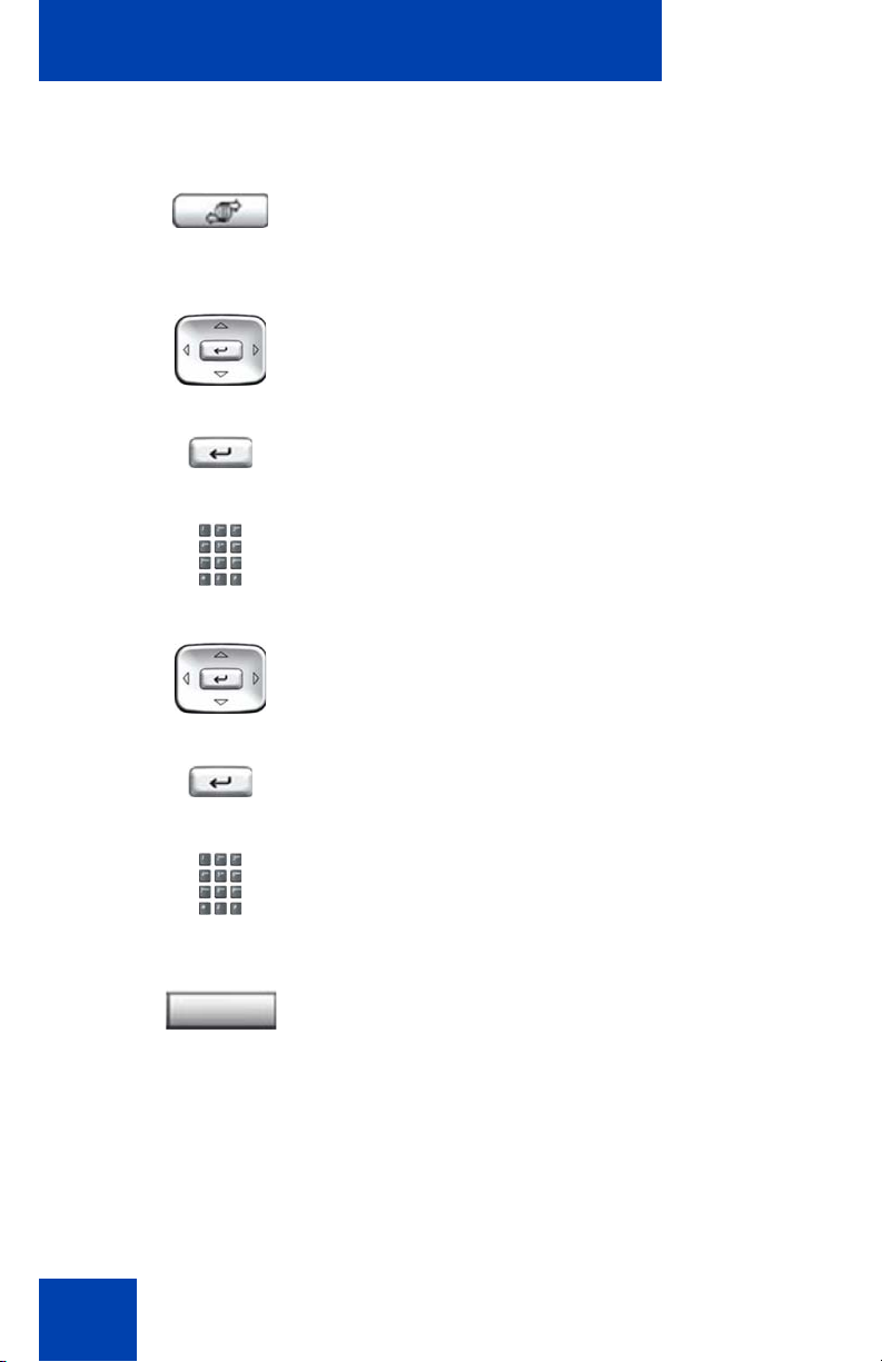
To configure default area codes (maximum of three):
1. Press the Up/Down navigation keys to
scroll and highlight Area Code Setup.
2. Press the Enter key.
3. Press the Up/Down navigation keys to
scroll and highlight one of the following:
— Area Code # 1
— Area Code # 2
— Area Code # 3
4. Press the Enter key.
5. Use the dialpad to enter the number at
the prompt.
6. Choose one of the following:
—Press the Select soft key to save the
configuration.
— Press the Cancel soft key to keep
the existing configurations.
71
Page 72

Configuring Telephone Options
or
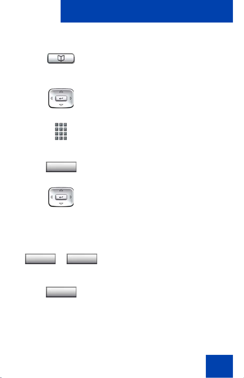
To edit area code display:
1. Press the Up/Down navigation keys to
2. Press the Enter key.
3. Press the Up/Down navigation keys to
4. Press the Enter key.
scroll and highlight Area Code Setup.
scroll and highlight one of the following:
— Area Code # 1
— Area Code # 2
— Area Code # 3
5. Use the dialpad to edit the number.
6. Choose one of the following:
—Press the Select soft key to save the
configuration.
— Press the Cancel soft key to keep
existing configurations.
Choosing a ring type
The Ring type… option configures the IP Phone ring tone. To choose a
ring type, press the Services key, select Telephone Options, and select
Ring type…
72
Page 73

To select a ring type:
or
Configuring Telephone Options
1. Press the Up/Down navigation keys to
scroll and highlight one of the ring types.
2. Press the Play soft key to sample the
ring tone.
3. Choose one of the following:
—Press the Select soft key to save the
ring type and return to the
Telephone Options menu.
— Press the Stop soft key and use the
Up/Down navigation keys to select a
different ring type.
— Press the Cancel soft key to keep
existing configurations.
Enabling or disabling Call Timer
The call timer measures how long you are on each call. To enable Call
Timer, press the Services key, select Telephone Options, and select
Call Timer.
To enable or disable Call Timer:
1. Choose one of the following:
— To turn on the call timer, press the
On soft key.
— To turn off the call timer, press the
Off soft key.
73
Page 74

Configuring Telephone Options
or
or
2. Choose one of the following:
—Press the Select soft key to save the
configuration and return to the
Telephone Options menu.
— Press the Cancel soft key to keep
existing configurations.
Enabling OnHook Default Path
The OnHook Default Path option allows you to choose whether to use a
headset or the Handsfree feature to operate your IP Phone while it is onhook.To enable OnHook Default Path, press the Services key, select
Telephone Options, and select OnHook Default Path.
To enable OnHook Default Path:
1. Press the Up/Down navigation keys to
highlight one of the following:
— Handsfree enable
— Headset enable
2. Choose one of the following:
—Press the Select soft key to save t he
default path and return to the
Telephone Options menu.
— Press the Cancel soft key to keep
existing configurations.
Changing feature key labels
The Change feature key label option renames the label displayed next to
each feature key or restores the default labels to the keys (collectively or
individually). To rename feature key labels, press the Services key,
select Telephone Options, and select Change feature key labels.
74
Page 75

Configuring Telephone Options
or
Note: If a feature key is configured as an auto-dial key, the label does
not change if the auto-dial key configuration changes.
To rename the labels:
1. Press the Enter key.
2. Press the feature key that you are
changing.
If you press a prime DN key, an error
message appears.
3. Enter the new information for the feature
key label. To enter special characters,
press the Up navigation key. For
information about entering text, refer to
“Entering text using the IP phone
dialpad” on page 30.
4. Choose one of the following:
—Press the Select soft key to save the
changes and return to the
Telephone Options menu.
— Press the Cancel soft key to keep
existing configurations.
To restore the default labels:
To restore feature key labels, press the Services key, select Telephone
Options, and select Change feature key labels.
5. Press the Enter key.
75
Page 76

Configuring Telephone Options
6. Use the Up/Down navigation keys to
scroll and highlight one of the following:
a. Restore all key labels
— Press the Yes soft key to change all
feature keys to default values.
b. Restore one key label
— Press the Select soft key.
— Press the feature key.
—Press the Yes soft key to change the
selected feature key label to the
default value.
Note: If labels are changed to default
values, you cannot undo the change.
The label configurations must be
reentered.
Configuring the name display format
You can configure your IP Phone 1140E to display the name of the
incoming calling party in the following formats:
• first name, last name
• last name, first name
To configure name display format, press the Services key, select
Telephone Options, and select Name Display Format.
To configure name display format:
1. Press the Up/Down navigation keys to
scroll and highlight Name display
format.
76
Page 77

Configuring Telephone Options
or
2. Press the Enter key.
3. Press the Up/Down navigation keys to
scroll and highlight one of the following:
— first name, last name
— last name, first name
4. Choose one of the following:
—Press the Select soft key to save the
configuration.
— Press the Cancel soft key to keep
existing configurations.
Configuring Live Dialpad
The Live Dialpad option activates the Primary DN key when you make a
call by dialing a directory number on the dialpad without picking up the
handset or pressing the handsfree key.
To configure Live Dialpad, press the Services key, select Telephone
Options, and select Live Dialpad.
To configure Live Dialpad:
1. Press the Up/Down navigation keys to
scroll and highlight Live Dialpad.
2. Press the Enter key.
77
Page 78

Configuring Telephone Options
or
3. Press the Up/Down navigation keys to
scroll and highlight one of the following:
— On
— Off (default)
4. Choose one of the following:
—Press the Select soft key to save the
configuration.
— Press the Cancel soft key to keep
existing configurations.
Configuring Caller ID display order
Caller ID display order appears in 2 formats:
• Number, name (default)
• Name, Number
Use the following procedure to configure Caller ID display order.
1. Press the Services key, select Telephone Options and select Caller
ID display order.
2. Press the Up/Down navigation keys to scroll and select one of the
following:
— Number, name (default)
— Name, number
3. Press the Select soft key to save the configuration, else press the
Cancel key to cancel the modifications.
Configuring Normal mode indication
The Normal mode display indication can be On or Off when the IP Phone
is in normal mode.
Use the following procedure to configure Normal mode indication.
78
Page 79

Configuring Telephone Options
1. Press the Services key, select Telephone Options, and select
Normal mode indication.
2. Press the Up/Down navigation keys to scroll and select one of the
following:
— On
— Off
3. Press the Select soft key to save the configuration, else press the
Cancel key to cancel the modifications.
79
Page 80

Configuring Local Menu options
Configuring Local Menu options
Note: Many of the options discussed in this section are for
administrator use only. Do not make any changes unless instructed
by an administrator.
Your system administrator can establish a password for the Local Tools
menu. When the password is enabled, a password prompt dialog box
appears when you attempt to access this menu. If this happens, contact
your system administrator.
Your IP Phone 1140E has both local and server-based options. Press th e
Services key twice to access the Local Tools menu, which is organized
into the following submenus:
• “Using the 1. Preferences submenu” on page 82
• “Using the 2. Local Diagnostics submenu” on page 103
• “Using the 3. Network Configuration menu” on page 105
• “Using the 4. Lock Menu” on page 106
If a menu entry has a number in front of it, you can select that entry by
pressing the associated key on the dialpad. For example, in the Local
Tools menu, you can access 2. Local Diagnostics by pressing the 2 key
on the dialpad.
The function of some keys on the IP Phone varies depending on the
situation. The key functions in the menus are descr ibed in Table 6.
Table 6: Navigation key functions in menus (Part 1 of 2)
Key Function
Down arrow keys Move the highlight down
Up arrow keys Move the highlight up
Right arrow key Select the current menu item
Left arrow key Close the menu
Enter key Select the current menu item
80
Page 81

Configuring Local Menu options
Table 6: Navigation key functions in menus (Part 2 of 2)
Key Function
Enter digits on the
Select the associated menu item
dialpad
Stop soft key Close the menu
The key functions in dialog boxes are described in Table 7.
Table 7: Navigation key functions in dialog boxes
Key Function
Down arrow keys Scroll the window down
Up arrow keys Scroll the window up
Right arrow key Go to the next Edit item
Left arrow key Go to the previous Edit item
Enter key Toggle Edit mode on or off
Toggle the check box status
If you are working in Edit mode, the first field of the item is highlighted and
a blinking cursor is to the right of the current edit positio n. The navigation
key functions in Edit mode are described in Table 8.
Table 8: Navigation key functions in Edit mode (Part 1 of 2)
Key Function
Down arrow keys Open the list
Move the highlight down the list
Up arrow keys Move the highlight up list
Right arrow key Select the current list item
Move the cursor to the right
Left arrow key Delete a character in the edit field
81
Page 82

Configuring Local Menu options
Table 8: Navigation key functions in Edit mode (Part 2 of 2)
Key Function
Enter key Select the highlighted item in the
Exit edit mode box
Enter characters
or digits on the
dialpad
If you are using a USB mouse, you can right-click on the Telephony
screen to open the Local Tools menu, and click on an item to select it.
Insert characters or digits at the current cursor
position
Using the 1. Preferences submenu
The Local Tools menu 1. Preferences submenu offers the following
choices:
• “Changing 1. Display Settings” on page 82
• “Changing 2. Language” on pag e 83
• “Configuring 3. Headsets” on page 84
• “Configuring 4. Bluetooth” on page 91
Changing 1. Display Settings
The Display Settings menu provides access to two tools: Contrast and
Sleep. Use the Contrast tool to alter the physical settings of the display.
Use the Sleep tool to control how long the display remains lit if th e phone
is inactive.
Note: Changes you make to contrast in this men u ar e lost if the
phone is reset. To avoid losing your changes, Nortel recommends
that you use the Contrast Adjustment control in the Telephone
Options menu.
To adjust Contrast or Sleep settings, press the Services key twice to
open the Local Tools menu, press the 1 key on the dialpad to select
1. Preferences, and press the 1 key on the dialpad to select
1. Display Settings.
82
Page 83

To adjust Contrast or Sleep settings:
1. Press the Up/Down arrow keys to scroll
and highlight one of the following:
— Contrast
— Sleep
Sleep appears in the format xxx, where
xxx is a time in minutes or hours.
2. Press the Enter key.
3. Press the Up/Down arrow keys to
increase or decrease the selected value.
Available values for Sleep are as follows:
5m (5 minutes)
15m (15 minutes)
30m (30 minutes)
1h (1 hour — default)
2h (2 hours)
Never (screen does not go black)
Configuring Local Menu options
Note: Extending the sleep time, or
setting it to Never, reduces the life span
of the display screen.
4. Press the Exit soft key to exit to the main
display. Changes are saved
automatically.
Changing 2. Language
Use the Preferences menu item to configure local preferences. Use the
Language tool to select the language used on your phone.
83
Page 84

Configuring Local Menu options
or
Note: This language setting controls the language used in the local
menus on your phone only. To select the language used by features
on your phone, press the Services key, select Telephone Options,
and select Language…
To select the language used in the local menus, press the Services key
twice to open the Local Tools menu, press the 1 key on the dialpad to
select 1. Preferences, and press the 2 key on the dialpad to select
2. Language.
To select the language used in local menus:
1. Press the Up/Down navigation keys to
scroll and highlight the desired language
(for example, German [Deutsche]).
2. Choose one of the following:
—Press the Select soft key to save the
desired language and return to the
Telephone Options menu.
— Press the Cancel soft key to keep
existing configurations.
3. Press the Exit soft key to exit to the main
display. Changes are saved
automatically.
Configuring 3. Headsets
Selecting Active Headset Devicee
To select the Active Headset Device, press the Enter key. Press the Up/
Down navigation keys to select the desired headset.
84
Page 85

To select the active headset device
or
1. Press the Up/Down navigation keys to
scroll and highlight the Headsets menu.
2. Choose one of the following:
—Press the Apply soft key to save the
— Press the Cancel soft key to keep
Note: You can select a headset
regardless of its connection status. It
does not have to be physically
connected to the IP Phone 1140E.
3. Press the Cancel soft key to exit to the
main display. Changes are saved
automatically.
Configuring Local Menu options
desired headset and return to the
Telephone Options menu.
existing configurations.
Enabling HID Commands
To enable HID Commands, press the Right/Left navigation key to open
the Local Tools menu, press the 1 key on the dialpad to select
1. Preferences, and press the 3 key on the dialpad to select 3.Headsets.
To enable HID Commands:
1. Press the Up/Down navigation keys to
scroll and highlight the Headsets menu.
85
Page 86

Configuring Local Menu options
or
2. Select the Enable HID Commands
checkbox.
3. Choose one of the following:
—Press the Apply soft key to save the
desired selection and return to the
Telephone Options menu.
— Press the Cancel soft key to keep
existing configurations.
4. Press the Cancel soft key to exit to the
main display. Changes are saved
automatically.
Enabling USB Headset
The wireless USB headset support included in UNIStim firmware release
3.1 for IP Phones is the Jabra GN9330E USB4 and the Plantronics CS50USB and CS60-USB. The Plantronics CS50-USB utilizes 900MHz
wireless technology whereas the Plantronics CS60- USB and Jabra
GN9330E USB utilize 1.9Mz DECT wireless technology. These wireless
headsets provide wireless freedom typically in the range of 60 meters or
200 feet. The actual distance allowed, before acceptable audio quality is
threatened, is dependant on the operating environment.
Included in the support of the Jabra and Plantronics headsets is
compliance to GN Netcom’s and Plantronic’s USB Human Interface
Device (HID) respectively. Compliance to their HID allows the phone to
recognize call controlling features from the headset including off-hook
(call answer/call initiate), on-hook (call release), mute, and volume
control.
To enable USB headset
86
Page 87

Configuring Local Menu options
1. Select the Headset option in the Preferences menu of the IP Phone
1120E, IP Phone 1140E, and IP Phone 1150E. See the following
Figure.
Making a change in the Headset menu page will take affect immediately,
but only temporarily depending on what further action is taken.
2. Press the Apply button to make the changes permanent.
3. Press Cancel button to discard any changes.
87
Page 88

Configuring Local Menu options
4. Select the appropiate headset type in the Active Headset Device
field from a list of Wired, USB, or Bluetooth as depicted in the
following figure.
5. Select the Enable HID Commands check box to provide full
HID for supported headsets.
6. Select the Headset type from the following list of headsets.
• DuraPlus-B (GN Netcom DuraPlus Binaural Headset)
• DuraPlus-M (GN Netcom DuraPlus Monaural Headset)
• GN2020 (GN Netcom GN2020 NC Monaural Headset)
• GN2100 (GN Netcom GN2100 Monaural Headset)
• GN2115 (GN Netcom GN2115 ST Binaural Headset)
• GN2117 (GN Netcom GN2117 ST Monaural Headset)
• GN2125 (GN Netcom GN2125 NC Binaural Headset)
• GN2220 (GN Netcom GN2220 NC Monaural Headset)
• GN2225 (GN Netcom GN2225 NC Binaural Headset)
• Nortel Handset
You can select the headset type and configure as the active headset
device regardless of whether the headset is connected or not.
88
Page 89

Configuring Local Menu options
Note: You can select the Headset Type only for the Nortel USB
Headset Adapters. If the Nortel USB Headset Adapter is not
detected, the Headset Type selection is disabled and cannot be
modified.
7. Select the Back Light check box to control the backlight on the
Nortel USB Headset Adapters. This check box is selected by
default.
Note: If the Nortel USB Headset Adapter is not detected this item is
disabled and cannot be modified.
Limitations and Advisories
• USB headsets consume power from the USB port in order to op erate.
The USB port on the IP Phone imposes a limit of only 100mA.
The
limit of 100mA is sufficient to power the Nortel USB Adapters
but is not sufficient to power the wireless headsets from GN
Netcom an Plantronics. Also 100mA is not sufficient to power
the Algo 4900 USB ATA.
• USB Audio support does not include stereo audio.
• Changes have occurred regarding the provisioning of Bluetooth on
the IP phone 1140E and 1150E.
setup page no longer provides the option to select Bluetooth
With UNIStim 3.1, the Bluetooth
89
Page 90

Configuring Local Menu options
headset since this choice has been moved to the Headset
menu.
• Users of USB Audio on an IP Phone 1120E or IP Phone 1140E when
connected to a BCM system may experience constant beeping from
the wireless headsets if the user inadvertently hits a call control keys
in error.
• For the Nortel USB Adapters it is a requirement that the firmware of
this device be V2.0.32 or later.
• For the Algo 4900 USB ATA it is a requirement that the firmware of
this device be v1.00.32 or later.
• The Algo 4900 USB ATA is classified as a high power USB device
and must be connected to the phone through a powered USB hub.
• The Plantronics CS50-USB and CS60-USB must be AC powered
prior to connecting them to phone.
• For the Plantronics CS50-USB and CS60-USB please make sure the
headset base is in ready mode (i.e. the green LED on th e rig ht ha n d
side of the headset cradle is solid) before using the headset.
• For the Plantronics CS50-USB and CS60-USB the On Hook/Off Ho ok
button must be depressed for 3 seconds to go off hook.
• At the time of this writing, GN Netcom produces four models of the
Jabra GN9300 series headsets: Jabra GN9330, Jabra GN 9330E,
Jabra GN 9350 and Jabra GN9350E.
The USB Audio feature in
the IP Phones only supports the Jabra GN9330E and Jabra
GN9350E connected via USB.
• For the GN Netcom 9300 series occasionally a single ring is lost
between the phone and the headset but is recovered at the next ring.
• For the GN Netcom 9300 series occasionally a drop in audio quality
may be experienced when a 3-way conference is established.
Nortel Mobile Headset Adapter properties
You can use the Nortel Mobile Headset Adapter to answer calls whenever
the IP Phone 1140E is running.
To access the Nortel Mobile Headset Adapter (MHA) properties, press
the Services key twice to open the Local Tools menu, press the 1 key on
90
Page 91

Configuring Local Menu options
the dialpad to select 1. Preferences, and press the 3 key on the dialpad to
select 3.Headsets.
Note: The Headset type and Backlight options are only available
when MHA is attached.
Table 7 describes the features of the Nortel Mobile Hea ds et Adapte r.
Table 9: Nortel Mobile Headset Adaptor elements and
functions
Key Function
Answer key Press to answer an incoming
call.
If there is no incoming call, the IP
1140E handset selects a line and
you hear a dial tone. This is also
referred to as Off-hook.
Release/Goodbye key This is also referred to as On-
hook.
Mute key Press the Mute key to listen to
the receiving party without
transmitting.
Press the Mute key again to
return to two-way conversation.
Volume key Use the Volume buttons to
increate or decrease the volume
of the headset.
Backlight The backlight illuminates when
you connect your headset to the
IP Phone 1140E.
Configuring 4. Bluetooth
Your IP Phone 1140E is equipped with a radio system to support
Bluetooth wireless technology enabled headsets. Double press the
Headset key to open the Bluetooth Setup dialog box. You must be
91
Page 92

Configuring Local Menu options
(Headset)
familiar with the operation of the navigation keys to work in the Bluetooth
Setup dialog box; see the Navigation keys description on page 21.
The Bluetooth Setup menu entry is not available on all phones. If the
Bluetooth Setup menu entry appears dimmed, or fails to open when you
double press the Headset key, the feature is not enabled on your phone.
Before you can use a wireless headset with your phone, the feature must
be enabled by the system administrator. Contact your administrator to
find out if Bluetooth wireless technology functionality is available for your
use.
Note: Nortel recommends that you not p air mo re than on e headset of
the same model, because they have identical names in the Paired
list.
To pair a wireless headset with your phone:
1. Double-press the Headset key to open
the Bluetooth Setup dialog box.
The Enable Bluetooth check box is
highlighted.
92
If the Bluetooth Setup menu fails to open
when you double press the Headset key,
Bluetooth wireless technology feature is
not enabled on your phone. Contact your
administrator.
2. Press the Enter key to activate
Bluetooth wireless technology.
A check mark is displayed on the Enable
Bluetooth item to indicate that the
Bluetooth wireless technology is
activated. The message “Bluetooth
Enabled” appears at the bottom of the
display.
Page 93

Configuring Local Menu options
3. Put your Bluetooth technology headse t
in its pairing or search mode. The
procedure for doing this can be different
for each headset. Refer to the
documentation that accompanied your
headset, or contact the vendor.
93
Page 94

Configuring Local Menu options
4. Search devices.
a. Ensure that your headset is in
Pairing or Search Mode.
b. Press the Right navigation key
twice, and highlight the Search
button, displayed next to the Search
Devices item.
c. Press the Enter key.
The message "Searching…." appears. It
can take up to two minutes for the
search to complete.
If the search is successful, the message
"Search Completed Found Device(s)"
appears, and a list of devices that
support Bluetooth wireless technology
appears in the Found: list.
d. Choose one of the following:
— If the search is successful, proceed
to step Step 5 on page 95.
94
— If the search is not successful, the
message "Search completed. No
device found" appears. If this
happens, or if the headset times out
and exits search/pairing mode,
power off the headset, and repeat
steps Step 3 on page 93 and Step 4
on page 94.
If pairing is still unsuccessful, pair
the phone to another wireless
headset, or contact the headset
vendor.
Page 95

Configuring Local Menu options
5. When the name of your headset appears
in the Found: box, press the Stop soft
key or wait for the search to finish. Whe n
the search is complete, the message
"Search Completed Found Device(s)"
appears.
6. Choose one of the following:
• If the name of your headset appears in
the Found: box, proceed to step Step 7
on page 96.
• If your headset is not displayed in the
Found: box, select your headset from
the list, as follows:
a. Press the Right navigation key one
or more times to highlight the
Found: box. Press the Enter key to
start the edit mode.
b. Press the Down navigation key to
open the Found: list. Press the Up/
Down navigation keys to scroll and
highlight your headset.
c. Press the Enter key to select the
headset and close the list. Press the
Enter key to exit edit mode.
95
Page 96

Configuring Local Menu options
7. Press the Right navigation key one or
more times to highlight the Pair button
(next to the Pair Device item) and press
the Enter key.
a. A dialog box appears, with the
prompt "Enter PIN#".
b. Use the phone dialpad to enter the
PIN for the wireless headset and
press the Enter key.
Check your headset documentation
to find its PIN (sometimes called a
passkey). Typically this value is
0000.
96
Page 97

Configuring Local Menu options
8. Choose one of the following:
• If the headset is successfully paired with
your phone, proceed to step S tep 9 on
page 98. To verify that the pairing was
successful, ensure that the headset
appears in the list next to the Paired:
item. If pairing is successful, the
message "Pair completed" also appears
at the bottom of the screen.
• If the headset is not successfully paired
with your phone, an error message
appears at the bottom of the screen. If
an error message appears:
— Confirm that the wireless headset is
still in search/pair mode.
— If the headset timed out and exited
search/pairing mode, put the
headset in pairing mode, as
discussed in step Step 3 on page 93,
and repeat step Step 7 on page 96.
— Check that you are using the correct
PIN and repeat step Step 7 on page
96.
97
Page 98

Configuring Local Menu options
9. Choose one of the following:
• If the name of your headset appears in
• If more than one device is paired, and
the Paired: box, proceed to step Step 10
on page 99.
the one you wish to use is not shown in
the Paired: box, navigate to the one you
want, as follows:
a. Press the Right navigation key one
or more times to highlight the
Paired: box. Press the Enter key to
start the edit mode.
b. Press the Up/Down navigation keys
to open the list. Press the Up/Down
navigations key to scroll in the
Paired: list and highlight your
headset.
c. Press the Enter key to select the
headset and close the list. Press the
Enter key to exit edit mode.
98
Page 99

Configuring Local Menu options
10. Choose one of the following:
• If only one headset is paired, proceed to
step Step 11 on page 99.
• If more than one wireless headset is
paired, the first headset paired is
automatically made the active device. To
make a different headset active, do the
following.
— Press the Right navigation key one
or more times to highlight the Set
button (next to the Set Active Device
item).
— Press the Enter soft key.
The message "Set active: “device name”
appears. This means the headset
named is now the active headset and is
used when you press the headset key.
11. Press the Exit soft key to exit to the main
display. Changes are saved
automatically.
Dual Pairing Headsets
Take special care when using a "dual pairing" type of Bluetooth wireless
technology headset, which can be paired to its base as well as to the
1140E. If it is paired to both, the 1140E is the second device, and the
following applies:
Press the headset "telephone" key:
• If a single tone sounds, the headset is connected to the base.
• If a double beep sounds, the headset is connected to the 1140E.
If the base is powered off, the headset is only paired to the 1140E and
pressing the "telephone" key connects you to the 1140E.
99
Page 100

Configuring Local Menu options
(Headset)
Note: Unless you need to dual pair a headset, o perating the headset
with the 1140E is simpler if the headset is only used with its chargingonly base. The desktop IP Phone base should be powered off if it is
not in use.
Interaction with wired headsets
If you connect a Bluetooth wireless technology headset and a wired
headset to the same IP Phone 1140E, the “Use Bluetooth headset” item
switches between the wired headset and the Bluetooth headset. If you
select the “Use Bluetooth Headset” check box, the Bluetooth headset
provides the audio. If you clear the “Use Bluetooth Headset” check box,
the wired headset provides the audio.
The Bluetooth wireless technology headset can work only if it is within
range of the phone; as the wireless headset approaches the edge of its
radio range, the audio quality degrades and radio interference noise
increases. When the wireless headset is in connecting range, the
Headset key controls the wireless headset, even if a wired headset is
attached. If a wireless headset moves out of connecting range, a special
beep sounds in the headset indicating the connection was lost.
When you do not want to use your Bluetooth technology headset
If a Bluetooth wireless technology headset is connected, and you want to
use the wired headset, you can switch between the two. It is not
necessary to unpair or disable the wireless headset.
You can switch between a wired and wireless headset and back again
either when the phone is idle or during an active call.
To switch between a wired headset and a wireless headset:
1. Double-press the Headset key to open
the Bluetooth Setup dialog.
2. Press the Left/Right navigation key to
select the “Use BT Headset” item.
100
 Loading...