

Avaya 100A Installation And User Instructions Manual
7KH$$QDORJ,QWHUIDFH0RGXOH
(for connection with the 6416D+M and 6424D+M Telephones)
Installation and User Instructions
[This module meets U.S. Analog Telephone Interface Requirements.]
Document Ordering No. 555-233-707
Comcode 108241951
Issue 1
June 1999
---------- INSTALLATION ----------
1
1A
2
1B
2
2
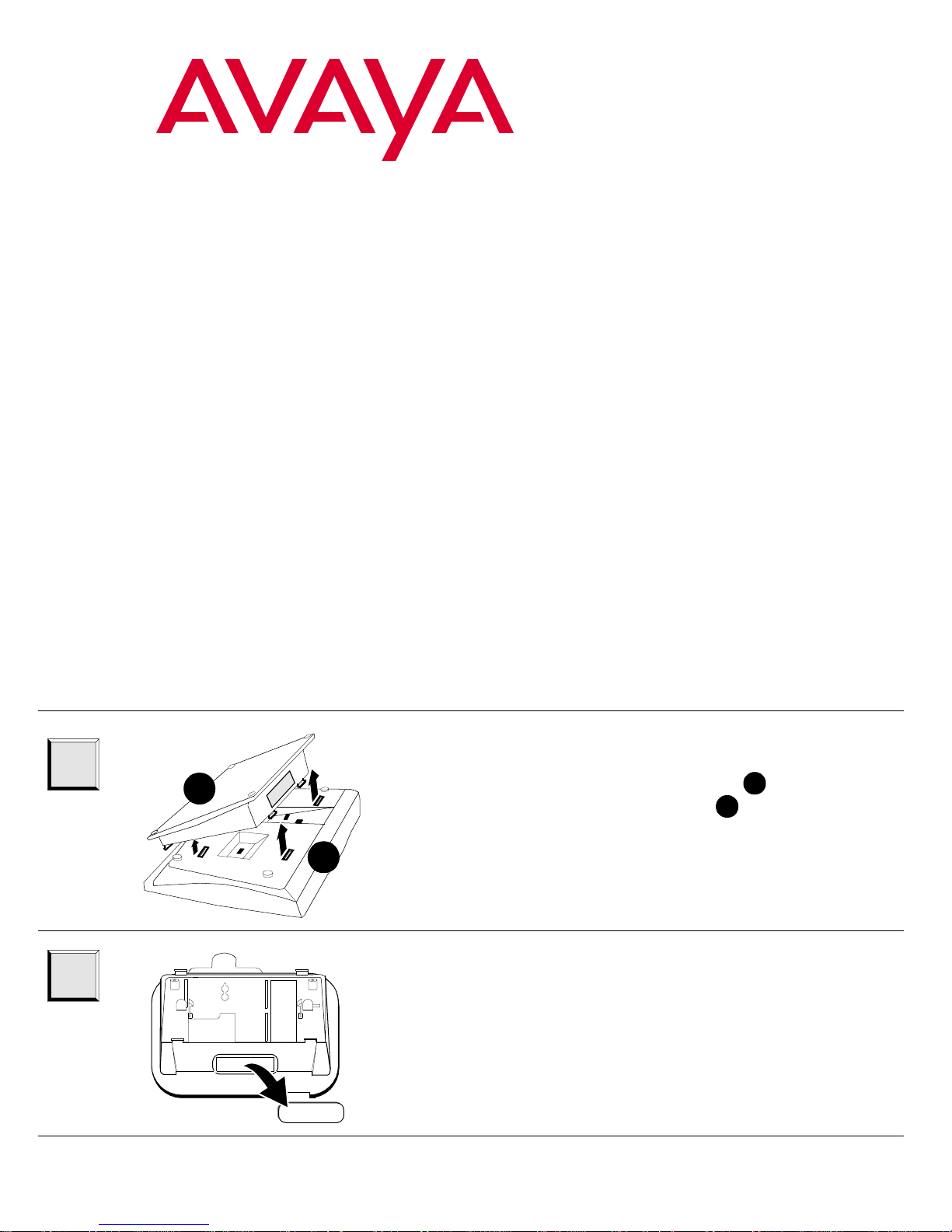
Remove the desktop stand ( ) from the
2
bottom of the telephone ( ). Push inward on
the top of the stand until you can lift the top of
the stand from the tab slots on the telephone.
Remove the cover from the module opening in
the desktop stand.
Hint: Keep the module opening cover nearby
for later use. See Step 8 for instructions on
storing the cover.
1
1A
1B
3
4
3B
3A
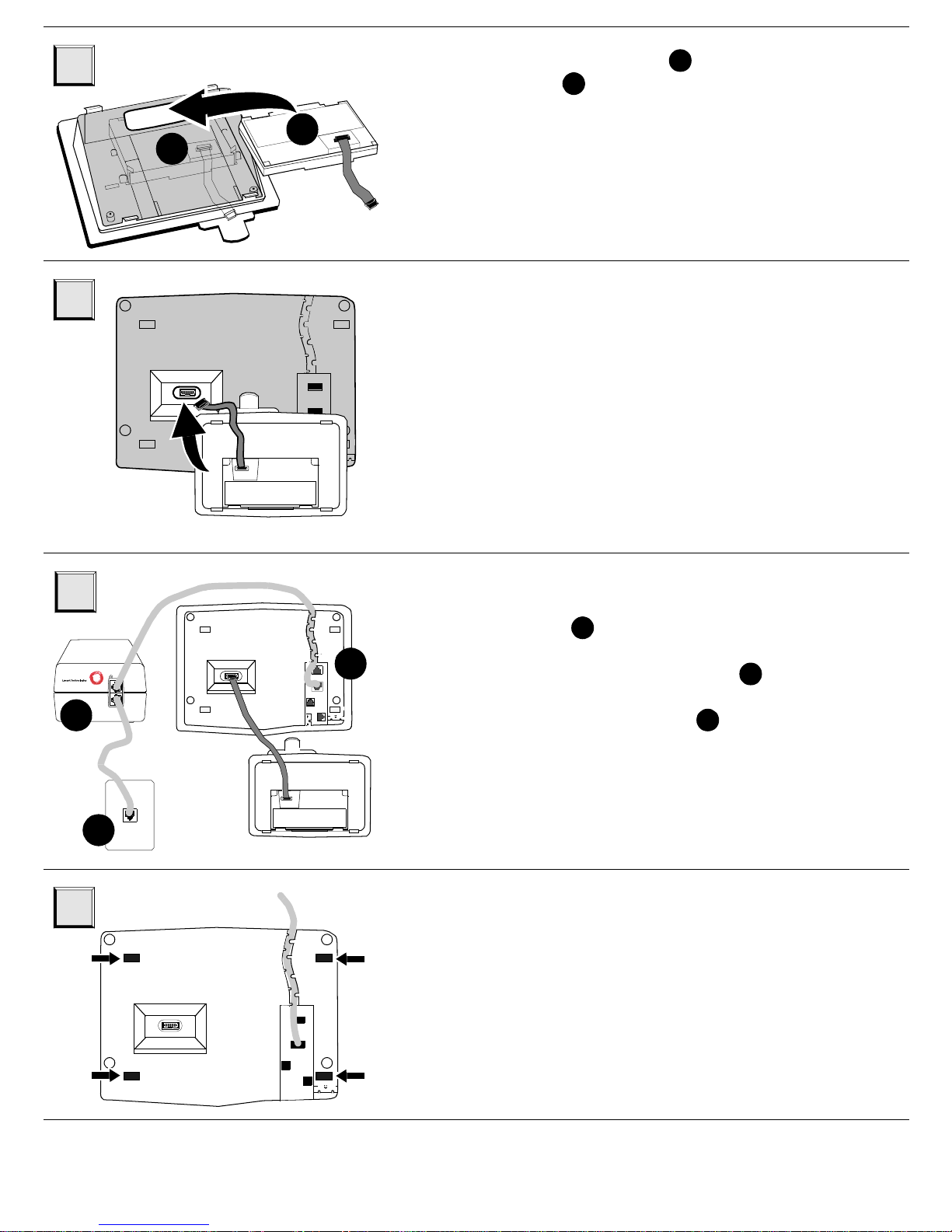
Install the module ( ) in the desktop
stand ( ). Push down until you hear the
3B
3A
module snap in place.
Hint: The analog adjunct jack on the module
should be poin ti ng tow ar d the module opening
on the desktop stand and the cable on the
module should be facing up.
Carefully align the module ribbon cable to the
mating receptacle on the bottom of the
telephone and insert slowly.
5
5A
6
D2R
5C
POWER ON
D8W
PHONE
-7 +8
LINE
5B
Connect the stand-alone local auxiliary power
supply ( ). With the D8W cord, connect the
5A
auxiliary power supply (the PHONE jack) to the
Line jack on the tele phone ( ). Then, conne ct
5B
the power supply (the LINE jack on the power
supply) to a wall jack ( ).
5C
Hint: The 100A module requires auxiliary
power, and you must use an 8-wire line cord
from the telephone to the power supply.
Replace the stand and m odule by lo weri ng the
desktop stand onto the bottom of the
telephone. The tabs on the stand must snap
into the appropriate slots on the bottom of the
telephone. (These slots are marked with
arrows in the accompanying drawing on the
left.)
2
 Loading...