


630
English
630/635/640
Operator’s Manual
2016-

Table of contents
600 Series
2
TABLE OF CONTENTS
Table of contents...............................................2
Introduction, warranty .....................................3
Safety instructions ........................................... 4
Description of the loader..................................7
Main parts of the loader..................................8
Signs and decals...............................................9
Technical specification...................................10
Load diagram ................................................12
Transporting instructions and tie down points .12
Operating instructions....................................13
Controls........................................................14
Control of loader boom, auxiliary
hydraulics and other functions ......................15
Attachment control switch pack...................15
Dashboard ....................................................16
Controls in the footwell................................16
Suspension seat.............................................17
Seat heater....................................................17
Battery disconnect switch.............................17
Telescopic boom...........................................17
Boom self levelling ........................................17
Boom floating................................................17
Smooth drive ................................................17
Joystick..........................................................18
Engine block heater ......................................18
Trailer coupling .............................................18
Hydraulic lifting device in the rear ................18
Extra counterweights....................................18
Drive release valve .......................................18
Anti slip valve ................................................18
Work light kit ................................................18
Headlight, beacon, blinker & reflector kit.....18
Tilt adapter ...................................................19
Extra auxiliary hydraulics outlets,
front and rear................................................19
Drive speed range selection switch (640).....19
Parking brake switch.....................................19
Snow chains ..................................................19
Light bar........................................................19
Starting the engine ........................................20
Stopping the engine ......................................20
Drive control ................................................21
Steering of the machine ................................22
Loader control ..............................................22
Using the auxiliary hydraulics........................22
Cabs ..............................................................23
Requirements for attachments......................24
Coupling the attachments.............................24
Hydraulic attachment coupling plate ............24
Coupling the hydraulic hoses of the attachment
......25
Service and maintenance instructions ...........26
Safety instructions for maintenance ..............26
Releasing the pressure of hydraulic system...26
Installing of service support and frame lock..27
Daily inspections ...........................................27
Maintenance schedule...................................27
Cleaning of the machine ...............................28
Greasing of the machine ...............................28
Battery check................................................28
Hydraulic oil level..........................................28
Changing of hydraulic oil filters.....................28
Hydraulic oil change......................................28
Check and tightening of bolts, nuts etc.........28
Check pressure of hydraulic system .............28
Adjust pressure of hydraulic system .............29
Adjust and change of slide pads on telescopic boom
29
Calibration of load sensor.............................30
Service, engine ..............................................30
Storage of the machine .................................30
Fuse box........................................................30
Jump start and auxiliary power .....................30
Safety instructions when handling the battery..30
Greasing points .............................................31
Refueling........................................................31
Light bulbs.....................................................31
Metal structures of the loader ......................31
Filters ............................................................32
Troubleshooting............................................33
Service history ..............................................34
EC Declaration of Conformity ........................35
Original instructions

Introduction, warranty
600 Series
3
Introduction
AVA NT TECNO OY wants to thank you for purchasing this AVANT loader. It is the result of Avants long
experience in design and manufacturing of compact loaders.
We ask you that you read and understand the contects of this manual completely before operating the loader.
This will improve your operating and maintenance efficiency, help avoid breakdowns and damage and extend
your machines life.
Contact your local AVANT dealer for any questions, service, spare parts or about any problems that may occur
with the operation of your machine.
Keep this Operators Manual with the machine at all times. If this Manual gets lost, ask for a new copy from
your Avant dealer. Remember also to give this Manual to the new owner when the machine changes ownership.
AVANT 600 series warranty
This warranty specifically applies to the AVANT 600 series loader only and not to any attachments used with
this product.
Any repairs or modifications performed without the prior authorisation of Avant Tecno Oy will cancel this
warranty.
During the first two years of operation or first 1000 hours (whichever is the soonest) Avant Tecno Oy warrants
to replace any part or repair any defect which may occur, subject to the terms detailed below:
1) The product has received regular maintenance in accordance with schedules given by the manufacturer.
2) Any damage caused by operation in a negligent manner or exceeding the approved specifications detailed
in this manual is excluded.
3) Avant Tecno Oy accepts no responsibility for interruption to working or any other consequential losses
resulting from any failure of the product.
4) Only Avant Tecno Oy approved replacement or original quality parts shall be used during routine maintenance.
5) Any damage caused by the use of incorrect fuel, lubricants, cooling liquid or cleaning solvents is excluded.
6) The Avant Warranty excludes any consumable parts (e.g. tyres, batteries, filters, belts etc.) except where
it can be clearly shown that these parts were defective on original supply.
7) Any damage caused resulting from the use of attachments not approved for use with this product is excluded.
8) In the event a fault occurs which is attributable to manufacturing or assembly defect you should arrange
to return your AVANT to your authorised dealer for repair. Travel and freight costs are excluded.
Intended use
AVANT 600 series loader is an articulated compact loader, designed and manufactured for both professional
and private use. The loader can be equipped with attachments offered by Avant Tecno Oy, which enables
doing of several different jobs. Because of this multi purpose nature of the machine and the various attachments
and tasks, read always not only this Manual but also the Operators Manual of the attachment, and follow all
instructions. Every person who has to do with this machine must follow work safety regulations, all other
generally accepted rules related to work health and safety, and all road traffic regulations.
Remember that safety consists of several factors. The loader, equipped with an attachment is very powerful
and can cause serious personal injuries or property damages if it is operated in a wrong or careless way. Do
not operate an attachment unless you have familiarised yourself with the use of it and the eventual dangers
related to it.
These operating instructions are intended to help to:
operate this machine safely and efficiently
observe and prevent situations that may cause a risk or danger
keep the machine in good condition and its life span as long as possible
This loader has been designed to require as little maintenance as possible. The operator can perform the most
common maintenance operations. There are however more demanding service operations that can be done
by professional service personnel only. It is allowed to perform service operations only when wearing appropriate
protective equipment. Original spare parts must be used. Familiarise yourself with the service and maintenance
instructions in this Manual.
Contact your local AVANT dealer, if you are uncertain of anything concerning the operation and maintenance
of this loader, or for any questions, service or spare parts.
Safety first
Following symbols are used throughout this Manual
to point out important things related to safety:
This safety symbol indicates important
safety instructions in this Manual. It warns
of an immediate hazardous situation that
can cause serious personal injuries or
property damages. Read carefully the
warning text next to this symbol and
make sure that all other operators are
aware of the warnings as well. It is a
question of safety of persons.
This attention symbol indicates important
instructions concerning correct use and
maintenance of this machine. If these
instructions are not followed, the
consequence can be breakdown of the
machine or property damage.
An incorrect or careless operation of the
loader may be the origin of a serious accident.
Before putting the machine into operation,
familiarise yourself with the use of the machine
and read and understand this Operators
Manual as well as the safety instructions.
Understand the limitations of speed, braking, steering
and stability as well as loading capacity of the machine
before starting operation. Make sure that every one
who operates or works with this equipment is familiar
with these safety precautions.
If you have no previous experience of the machine,
make sure to do all testing at a safe and open place
with no persons in the area of operation.
Read this Operators Manual, and also the
Operators Manual of the attachment(s) and
other safety instructions before starting operation.
General instructions
1. Remember the correct working position. When
driving be comfortably seated in the driver's seat,
fasten seat belt and keep it fastened always when
driving and working with the machine, keep your
feet in their proper place in the footwell and at
least one hand on the steering wheel.
2. Start the operation slowly and carefully. Practice
driving of the machine at a safe and open place
before connecting any attachment, follow the
instructions in this Manual.
3. Operate the control levers with ease and without
hesitation. Avoid abrupt movements when handling
the load, in order to prevent the load from falling
and to keep the machine stable.
4. Keep away from the danger zone of the lifted
boom and dont let anyone go there.
5. Keep your hands, feet and clothing away from all
moving parts, hydraulic components and hot surfaces.
6. Make sure that there is enough open space around
the machine for safe driving.
7. Do not transport the load with the boom lifted.
Always carry bucket or attachment as low as
possible, and put the load down whenever you
leave the machine.
8. Before leaving drivers seat:
Lower the loader boom and place attachment
flat on ground
Engage the parking brake
Stop the engine, remove the ignition key
9. It is not allowed to transport persons with this
machine. Do not transport or lift persons in the
bucket or in any other attachment. Lifting of persons
is only allowed with the attachment designed for
this purpose: Avant Leguan 50, following the
instructions in the Operators Manual of Leguan 50.
10. Do not exceed rated operating capacity. Familiarise
yourself with and follow the load diagrams in this
Manual.
11. When turning with the machine, remember that
the driver´s seat extends beyond the turning
radius of the wheels (collision risk).
12. Do not operate the loader in an explosive
environment or in a place where dust or/and gases
can create a fire or explosion hazard.
13. Keep the engine area clean of flammable materials.
14. Read the transportation instructions on page 12.
15. Switch off the battery disconnect switch during storage.
16. Follow all inspection, service and maintenance
instructions. If you notice any faults or damages
on the machine, these must be repaired before
starting operation.
17. Before any maintenance or repair operation always
stop the engine, lower the boom down and release
pressure from hydraulic system. Read safety
instructions for maintenance on page 26.
18. Do not let any person operate this loader who
has not read safety instructions and is not familiar
with the safe and correct use of this loader.
Operation on gradients
19. Load, unload, and turn on flat level ground only.
Drive slowly on uneven terrains. Do not drive on
too steep a gradient - watch out for ditches,
manholes and steep gradients.
20. Do not park the machine on a surface with a
gradient. Should this be necessary, engage the
parking brake and preferably turn the machine
sideways and put down the load. If needed, use
chocks behind the wheels.
Safety instructions
4
600 Series
Safety instructions
5
Handling of heavy loads and load sensor
The loader is equipped with a load sensor system. It
gives an audible warning signal and at the same time
an indicator lights in the dashboard when there is a risk
that the machine tips over its front axle. When the
system gives a warning signal the load that is being lifted
is too heavy in relation with the lift capacity of the
loader. In this case one has to either put more counterweights
on the loader or relieve the load that is being lifted.
When the load sensor starts to warn, there is
a risk that the machine tips over its front axle.
In this case stop lifting of the boom, retract
the telescopic boom and lower down the boom
slowly. When the load sensor is warning do
not steer the machine before the boom is
lowered down close to ground level. Lift the
boom only when the loader chassis is straight.
Keep the load as close to ground as possible.
Never take a heavy load on the loader from
high level e.g. from truck, shelf etc. risk
of tipping over!
Always put the load down on the ground before
leaving the machine. When loading, always
keep the loader chassis as straight as possible.
Personal safety and protective equipment
Wear safe clothing and personal protective equipment
(PPE). Protect yourself against work hazards like noise,
ejecting debris or dust for example.
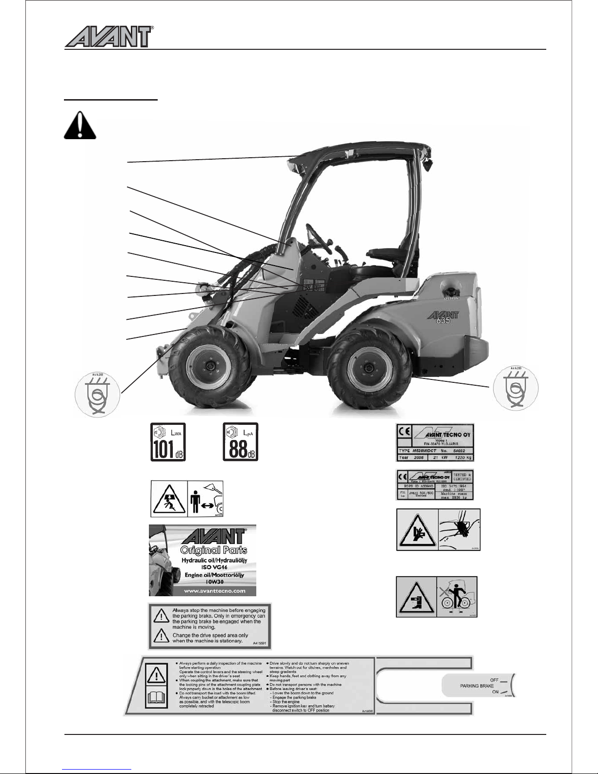
Noise level at drivers seat can exceed
85 dB(A). Wear hearing protection
when working with the loader.
It is recommended to wear safety
footwear when working with the loader.
Wear protective gloves when handling
hydraulic hoses.
Follow regulations regarding
protective equipment. Wear eye
protection and hard hat or other
protective equipment as needed.
Read Operators Manual of the attachment for more information
about protective equipment needed in the work.
Safety frame (ROPS) and safety canopy (FOPS)
Safety frame (ROPS) protects the operator in
case the machine tips over. Always fasten the
seat belt in order to stay inside the safety frame
protective area. Never take off the safety frame.
The loader is also equipped with a falling objects
protective canopy (FOPS).
Electric system
Lead acid batteries can produce flammable and
explosive gases. Make sure that the ventilation is
sufficient and keep arcs, sparks, flames and lighted
tobacco away from battery.
Battery acid causes severe burns. In case of acid
contact, wash immediately with water for several
minutes and get medical attention in case of eye
contact.
Read the instructions for jump start on page 30.
Never charge a frozen battery.
600 Series

Safety instructions
6
600 Series

Description of the loader
600 Series
Description of the loader
7
Identification of the loader
Write down the identification information of your loader in the following
fields, it facilitates ordering of spare parts etc.
1. Loader model___
__________________________________________
2. Loader serial no.___________
________________________________
3. Engine serial no.___________________________________________
Serial number of the loader is printed on the type plate (see page 9),
which also indicates the loader model.
Location of engine serial number can be found in the Operators Manual
of the engine.
Dealer:____________________________________________________
Contact information:__________________________________________
__________________________________________
Multi connector
Pressure 2
Tank line
Pressure 1
Attachment
control switch
pack socket
(option)
l
j
k
m
n
o
p
q
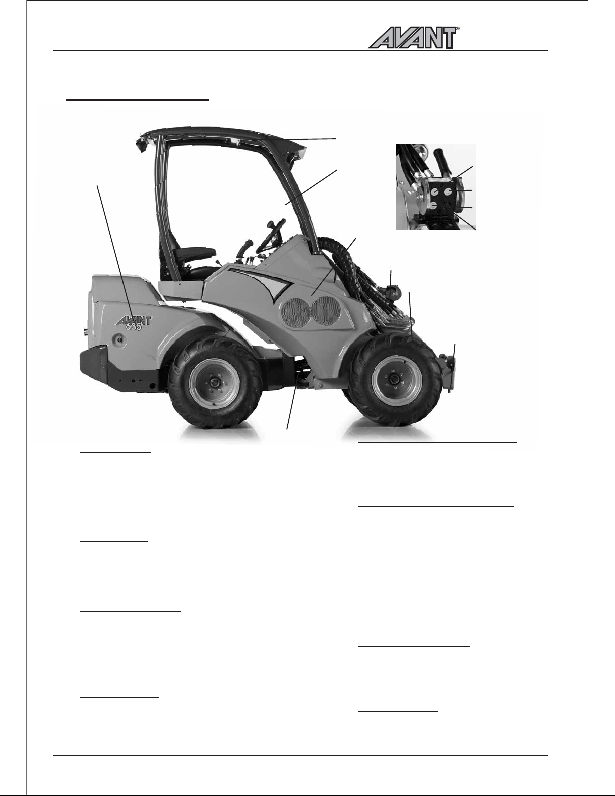
Main parts of the loader
Following picture shows the main parts of the loader:
l
j
k
m
Front frame
On the front frame are mounted: drivers seat,
operating controls, parking brake, hydraulic control
valves, hydraulic oil tank, auxiliary hydraulics outlet,
front wheels, hydraulic motors and the loader boom
with attachment coupling plate.
Back frame
On the back frame are mounted: engine with
accessories, battery, fuel tank, hydraulic pumps, rear
wheels, hydraulic motors.
Articulation joint
Articulation joint connects the front and back frame.
The loader is steered hydraulically by the steering
cylinder which is mounted between the front and
back frames. Hydraulic hoses and electric wires are
conducted through the articulation joint.
n
o
Attachment coupling plate
Attachments are mounted on the
attachment coupling plate. The locking pins
on the plate can be operated manually
(standard) or hydraulically (option).
Auxiliary hydraulics outlet
The hydraulic hoses of hydraulically operated
attachments are mounted on this outlet. The
outlet is equipped with the multi connector
quick coupling system and is double acting: it
has two pressure lines and one tank line. Also
the optional attachment control switch pack
socket is mounted on the multi connector. In
addition, as an option, it is also possible to install
a single or double acting auxiliary hydraulics
outlet in the rear of the machine, or a double
acting outlet in the front under the multi connector.
p
q
ROPS safety frame
ROPS frame (Roll-over protective structure)
complies with the standard ISO 3471:1994
with Amendment 1:1997 and Technical
Corrigendum 1:2000.
FOPS canopy
FOPS canopy (Falling objects protective
structure) mounts on the ROPS. It meets
the ISO 3449:1992 (1365 J) criteria.
Loader boom
The attachment coupling plate is mounted on the
lower end of the boom. The boom is telescopic,
extending 600 mm hydraulically.
Description of the loader
8
600 Series
l
A417273
m
r
A414690
A414664
n
o
p
q
A415591
l
p
q
j
k
m
n
o
r
Signs and decals
Make sure that the following signs and decals clean, undamaged and readable. If any of these
decals is missing or is unreadable it should be replaced without delay. Ask for new decals
from your local Avant dealer.
j
k
600 Series
Description of the loader
9
Risk of crushing, keep hands and feet within
the drivers area
Risk of crushing, do not grip the steering
wheel from outside the machine or when
getting into the drivers seat.
Sound power level / Sound pressure level at drivers seat
Keep out from the danger zone of
the machine 2 pcs
A43600
A411047
A411456
A411455

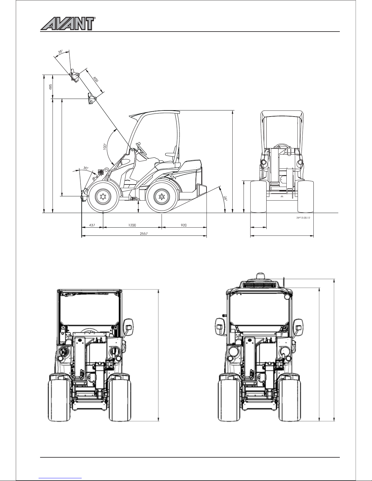
Technical specification
Model
Engine make & type
Function
Cooling system
Number of cylinders
Starter
Bore * stroke
Displacement
Max. output (ISO Gross)
Fuel
Fuel tank capacity
Engine oil type
Engine oil capacity
Charging current max.
Battery
Tipping load, see diagram on page 11.
Tyr e
23x10.50-12
23x10.50-12
27 x 8.50-15
26x12.00-12
320/60-12
26,5x14.00-12
Tyre pressure
2,5 bar
2,5 bar
2,5 bar
2,0 bar
2,0 bar
2,0 bar
Part no.
65997 TR
65996 Grass
65414 TR
65739 TR
65212 Grass
65224 TR
65787 Grass *)
Machine width
1130 mm
1130 mm
1030 mm
1290 mm
1290 mm
1480 mm
AVANT 630
Kubota D 1105
4 stroke
water
3
electric
78,0 * 78,4 mm
1124 cm
³
19 kW (26 hp)
diesel
30 l
API CC SAE 10W-30
5,1 l
40 A
12V 60Ah
AVANT 635/640
Kubota V1505
4 stroke
water
4
electric
78,0 * 78,4 mm
1498 cm
³
28 kW (37,5 hp)
diesel
30 l
API CC SAE 10W-30
6,4 l
40 A
12V 60Ah
AVANT 630/635/640
2557 mm
1290 mm
2034 mm
252 mm
1500/1530/1590 kg
26x12.00-12 tractor/grass
0 - 22 km/h
hydrostatic
38 l
AVANT 630: 44 l/min 200 bar
AVANT 635/640: 66 l/min 200 bar
900 / 2190 mm
2835 mm
1180 -1390 daN
1400 kg
1250 kg
88 dB (A)
101 dB (A)
< 2,5 m/s
²
< 0,5 m/s
²
Model
Length
Width
(with 26x12.00-12 wheels)
Height
Ground clearance
Weight, starting from
Standard wheels
Drive speed (depending on model)
Transmission, drive
Hydraulic oil tank capacity
Auxiliary hydraulics
Turning radius inside/outside
Max. lifting height
Max. pulling force
(depending on model)
Max. lifting capacity (hydr.)
Max. breakout force / 50 cm
Sound power level 2000/14/EC Lp
Sound pressure level 2000/14/EC Lw
Hand-arm vibration, total
Whole-body vibration, max.
Description of the loader
10
600 Series
Auxiliary hydraulics oil flow
1 pump
2 pump
0
10
20
30
40
50
60
70
80
1500
1600
1700
1800
1900
2000
2100
2200
2300
2400
2500
2600
2700
2800
2900
3000
3100
3200
3300
rpm
l/min
Max. auxiliary hydraulics oil flow can not
be used with all attachments. Check correct
engine rpm and auxiliary hydraulics pump
configuration for the attachment with the
help of this table and Operators Manual of
the attachment.
1 pump
2 pump
Avant 635/640
Avant 630
*) Requires spacer kit A418958 on the machine
(4 pcs 40 mm spacers, 5-bolt, part. no A417486)
600 Series Description of the loader
11
2835
1995
2034
252
620
300
2350
1030-1480
LX Cab, 2056
DLX Cab, 2083
DLX Cab with A/C on the roof, 2219
 Loading...