

Page 1
English
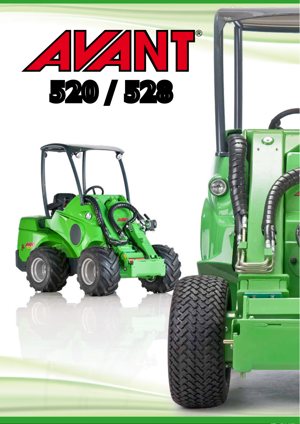
520 / 528
Operator’s Manual
2016-
Page 2

Table of contents
TABLE OF CONTENTS
500 Series
Table of contents...............................................2
Introduction, warranty .....................................3
Safety instructions ........................................... 4
Description of the loader..................................7
Main parts of the loader..................................8
Signs and decals...............................................9
Technical specification...................................10
Load diagram ................................................11
Transporting instructions and tie down points .12
Operating instructions....................................13
Controls........................................................14
Control of loader boom, auxiliary
hydraulics and other functions ......................15
Attachment control switch pack...................15
Dashboard ....................................................16
Controls in the footwell................................16
Suspension seat.............................................17
Telescopic boom ...........................................17
Boom self levelling ........................................17
Boom floating................................................17
Joystick..........................................................17
Work light kit ................................................17
Engine block heater ......................................18
Trailer coupling .............................................18
Extra counterweights....................................18
Headlight, beacon, blinker & reflector kit.....18
Drive circuit release switch ..........................18
Anti slip valve ................................................18
Battery disconnect switch.............................18
Light bar........................................................18
Tilt adapter ...................................................19
Extra auxiliary hydraulics outlets,
front and rear................................................19
Hydraulic lifting device in the rear ................19
Parking brake switch.....................................19
Snow chains ..................................................19
Starting the engine ........................................20
Stopping the engine ......................................20
Drive control ................................................21
Steering of the machine ................................22
Loader control ..............................................22
Using the auxiliary hydraulics........................22
Cabs ..............................................................23
Requirements for attachments......................24
Coupling the attachments.............................24
Hydraulic attachment coupling plate ............24
Coupling the hydraulic hoses of the attachment
Service and maintenance instructions ...........26
Safety instructions for maintenance ..............26
Releasing the pressure of hydraulic system...26
Installing of service support and frame lock..27
Daily inspections ...........................................27
Maintenance schedule...................................27
Cleaning of the machine ...............................28
Greasing of the machine ...............................28
Battery check................................................28
Hydraulic oil level..........................................28
Hydraulic oil filter change .............................28
Hydraulic oil change......................................28
Check and tightening of bolts, nuts etc.........28
Check of hydraulic pressure .........................29
Adjustment of hydraulic pressure .................29
Adjust and change of slide pads on telescopic boom
Service, engine ..............................................30
Storage of the machine .................................30
Fuse box........................................................30
Jump start and auxiliary power .....................30
Safety instructions when handling the battery..30
Greasing points .............................................31
Refueling........................................................31
Light bulbs.....................................................31
Metal structures of the loader ......................31
Filters ............................................................32
Troubleshooting ............................................33
Service history ..............................................34
EC Declaration of Conformity ........................35
......25
29
Original instructions
2
Page 3

500 Series
Introduction, warranty
Introduction
AVA NT TECNO OY wants to thank you for purchasing this AVANT loader. It is the result of Avants long
experience in design and manufacturing of compact loaders.
We ask you that you read and understand the contects of this manual completely before operating the loader.
This will improve your operating and maintenance efficiency, help avoid breakdowns and damage and extend
your machines life.
Contact your local AVANT dealer for any questions, service, spare parts or about any problems that may occur
with the operation of your machine.
Keep this Operators Manual with the machine at all times. If this Manual gets lost, ask for a new copy from
your Avant dealer. Remember also to give this Manual to the new owner when the machine changes ownership.
Intended use
AVANT 520/528 is an articulated compact loader, designed and manufactured for both professional and private
use. The loader can be equipped with attachments offered by Avant Tecno Oy, which enables doing of several
different jobs. Because of this multi purpose nature of the machine and the various attachments and tasks,
read always not only this Manual but also the Operators Manual of the attachment, and follow all instructions.
Every person who has to do with this machine must follow work safety regulations, all other generally accepted
rules related to work health and safety, and all road traffic regulations.
Remember that safety consists of several factors. The loader, equipped with an attachment is very powerful
and can cause serious personal injuries or property damages if it is operated in a wrong or careless way. Do
not operate an attachment unless you have familiarised yourself with the use of it and the eventual dangers
related to it.
These operating instructions are intended to help to:
operate this machine safely and efficiently
observe and prevent situations that may cause a risk or danger
keep the machine in good condition and its life span as long as possible
This loader has been designed to require as little maintenance as possible. The operator can perform the most
common maintenance operations. There are however more demanding service operations that can be done
by professional service personnel only. It is allowed to perform service operations only when wearing appropriate
protective equipment. Original spare parts must be used. Familiarise yourself with the service and maintenance
instructions in this Manual.
Contact your local AVANT dealer, if you are uncertain of anything concerning the operation and maintenance
of this loader, or for any questions, service or spare parts.
AVANT 520/528 WARRANTY
This warranty specifically applies to the AVANT 520/528 loader only and not to any attachments used with
this product.
Any repairs or modifications performed without the prior authorisation of Avant Tecno Oy will cancel this
warranty.
During the first two years of operation or first 1000 hours (whichever is the soonest) Avant Tecno Oy warrants
to replace any part or repair any defect which may occur, subject to the terms detailed below:
1) The product has received regular maintenance in accordance with schedules given by the manufacturer.
2) Any damage caused by operation in a negligent manner or exceeding the approved specifications detailed
in this manual is excluded.
3) Avant Tecno Oy accepts no responsibility for interruption to working or any other consequential losses
resulting from any failure of the product.
4) Only Avant Tecno Oy approved replacement or original quality parts shall be used during routine maintenance.
5) Any damage caused by the use of incorrect fuel, lubricants, cooling liquid or cleaning solvents is excluded.
6) The Avant Warranty excludes any consumable parts (e.g. tyres, batteries, filters, belts etc.) except where
it can be clearly shown that these parts were defective on original supply.
7) Any damage caused resulting from the use of attachments not approved for use with this product is excluded.
8) In the event a fault occurs which is attributable to manufacturing or assembly defect you should arrange
to return your AVANT to your authorised dealer for repair. Travel and freight costs are excluded.
3
Page 4
Safety instructions
500 Series
Safety first
Following symbols are used throughout this Manual
to point out important things related to safety:
This safety symbol indicates important
safety instructions in this Manual. It warns
of an immediate hazardous situation that
can cause serious personal injuries or
property damages. Read carefully the
warning text next to this symbol and
make sure that all other operators are
aware of the warnings as well. It is a
question of safety of persons.
This attention symbol indicates important
instructions concerning correct use and
maintenance of this machine. If these
instructions are not followed, the
consequence can be breakdown of the
machine or property damage.
An incorrect or careless operation of the
loader may be the origin of a serious accident.
Before putting the machine into operation,
familiarise yourself with the use of the machine
and read and understand this Operators
Manual as well as the safety instructions.
Understand the limitations of speed, braking, steering
and stability as well as loading capacity of the machine
before starting operation. Make sure that every one
who operates or works with this equipment is familiar
with these safety precautions.
If you have no previous experience of the machine,
make sure to do all testing at a safe and open place
with no persons in the area of operation.
Read this Operators Manual, and also the
Operators Manual of the attachment(s) and
other safety instructions before starting operation.
General instructions
1. Remember the correct working position. When
driving be comfortably seated in the driver's seat,
fasten seat belt and keep it fastened always when
driving and working with the machine, keep your
feet in their proper place in the footwell and at
least one hand on the steering wheel.
2. Start the operation slowly and carefully. Practice
driving of the machine at a safe and open place
before connecting any attachment, follow the
instructions in this Manual.
3. Operate the control levers with ease and without
hesitation. Avoid abrupt movements when handling
the load, in order to prevent the load from falling
and to keep the machine stable.
4. Keep away from the danger zone of the lifted
boom and dont let anyone go there.
5. Keep your hands, feet and clothing away from all
moving parts, hydraulic components and hot surfaces.
6. Make sure that there is enough open space around
the machine for safe driving.
7. Do not transport the load with the boom lifted.
Always carry bucket or attachment as low as
possible, and put the load down whenever you
leave the machine.
8. Before leaving drivers seat:
Lower the loader boom and place attachment
flat on ground
Engage the parking brake make sure that it
locks into locking position
Stop the engine, remove the ignition key
9. It is not allowed to transport persons with this
machine. Do not transport or lift persons in the
bucket or in any other attachment. Lifting of persons
is only allowed with the attachment designed for
this purpose: Avant Leguan 50, following the
instructions in the Operators Manual of Leguan 50.
10. Do not exceed rated operating capacity. Familiarise
yourself with and follow the load diagrams in this
Manual.
11. When turning with the machine, remember that
the driver´s seat extends beyond the turning
radius of the wheels (collision risk).
12. Do not operate the loader in an explosive
environment or in a place where dust or/and gases
can create a fire or explosion hazard.
13. Keep the engine area clean of flammable materials.
14. Read the transportation instructions on page 12.
15. Switch off the battery disconnect switch during storage.
16. Follow all inspection, service and maintenance
instructions. If you notice any faults or damages
on the machine, these must be repaired before
starting operation.
17. Before any maintenance or repair operation always
stop the engine, lower the boom down and release
pressure from hydraulic system. Read safety
instructions for maintenance on page 26.
18. Do not let any person operate this loader who
has not read safety instructions and is not familiar
with the safe and correct use of this loader.
Operation on gradients
19. Load, unload, and turn on flat level ground only.
Drive slowly on uneven terrains. Do not drive on
too steep a gradient - watch out for ditches,
manholes and steep gradients.
20. Do not park the machine on a surface with a
gradient. Should this be necessary, engage the
parking brake and preferably turn the machine
sideways and put down the load. If needed, use
chocks behind the wheels.
4
Page 5
500 Series
Handling of heavy loads
Never take a heavy load on the loader from
high level e.g. from truck, shelf etc. risk
of tipping over!
Always put the load down on the ground before
leaving the machine. When loading, always
keep the loader chassis as straight as possible.
Personal safety and protective equipment
Wear safe clothing and personal protective equipment
(PPE). Protect yourself against work hazards like noise,
ejecting debris or dust for example.
Noise level at drivers seat can exceed
85 dB(A). Wear hearing protection
when working with the loader.
It is recommended to wear safety
footwear when working with the loader.
Wear protective gloves when handling
hydraulic hoses.
Follow regulations regarding
protective equipment. Wear eye
protection and hard hat or other
protective equipment as needed.
Safety instructions
Read Operators Manual of the attachment for more information
about protective equipment needed in the work.
Safety frame (ROPS) and safety canopy (FOPS)
Safety frame (ROPS) protects the operator
in case the machine tips over. Always fasten
the seat belt in order to stay inside the safety
frame protective area. Never take off the
safety frame.
The loader is also equipped with a falling objects
protective canopy (FOPS).
Electric system
Lead acid batteries can produce flammable and
explosive gases. Make sure that the ventilation is
sufficient and keep arcs, sparks, flames and lighted
tobacco away from battery.
Battery acid causes severe burns. In case of acid
contact, wash immediately with water for several
minutes and get medical attention in case of eye
contact.
Read the instructions for jump start on page 30.
Never charge a frozen battery.
5
Page 6

Safety instructions
500 Series
6
Page 7

500 Series
Description of the loader
Description of the loader
Identification of the loader
Write down the identification information of your loader in the following
fields, it facilitates ordering of spare parts etc.
1. Loader model___
2. Loader serial no.___________
3. Engine serial no.___________________________________________
Serial number of the loader is printed on the type plate (see page 9),
which also indicates the loader model.
Location of engine serial number can be found in the Operators Manual
of the engine.
Dealer:____________________________________________________
Contact information:__________________________________________
__________________________________________
__________________________________________
________________________________
7
Page 8
Description of the loader
Main parts of the loader
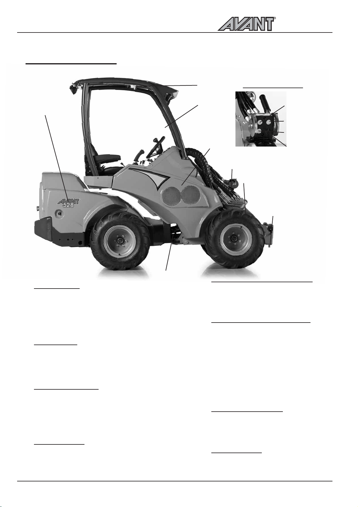
Following picture shows the main parts of the loader:
500 Series
k
q
p
j
Multi connector
o
m
n
Pressure 2
Tank line
Pressure 1
Attachment
control switch
pack socket
(option)
Front frame
j
On the front frame are mounted: drivers seat,
operating controls, parking brake, hydraulic control
valves, hydraulic oil tank, auxiliary hydraulics outlet,
front wheels, hydraulic motors and the loader boom
with attachment coupling plate.
Back frame
k
On the back frame are mounted: engine with
accessories, battery, fuel tank, hydraulic pumps, rear
wheels, hydraulic motors.
Articulation joint
l
Articulation joint connects the front and back frame.
The loader is steered hydraulically by the steering
cylinder which is mounted between the front and
back frames. Hydraulic hoses and electric wires are
conducted through the articulation joint.
Loader boom
m
The attachment coupling plate is mounted on the
lower end of the boom. The boom is telescopic,
extending 600 mm hydraulically.
l
Attachment coupling plate
n
Attachments are mounted on the
attachment coupling plate. The locking pins
on the plate can be operated manually
(standard) or hydraulically (option).
Auxiliary hydraulics outlet
o
The hydraulic hoses of hydraulically operated
attachments are mounted on this outlet. The
outlet is equipped with the multi connector
quick coupling system and is double acting: it
has two pressure lines and one tank line. Also
the optional attachment control switch pack
socket is mounted on the multi connector. In
addition, as an option, it is also possible to install
a single or double acting auxiliary hydraulics
outlet in the rear of the machine, or a double
acting outlet in the front under the multi connector.
ROPS safety frame
p
ROPS frame (Roll-over protective structure)
complies with the standard ISO 3471:1994
with Amendment 1:1997 and Technical
Corrigendum 1:2000.
FOPS canopy
q
FOPS canopy (Falling objects protective
structure) mounts on the ROPS. It meets
the ISO 3449:1992 (1365 J) criteria.
8
Page 9
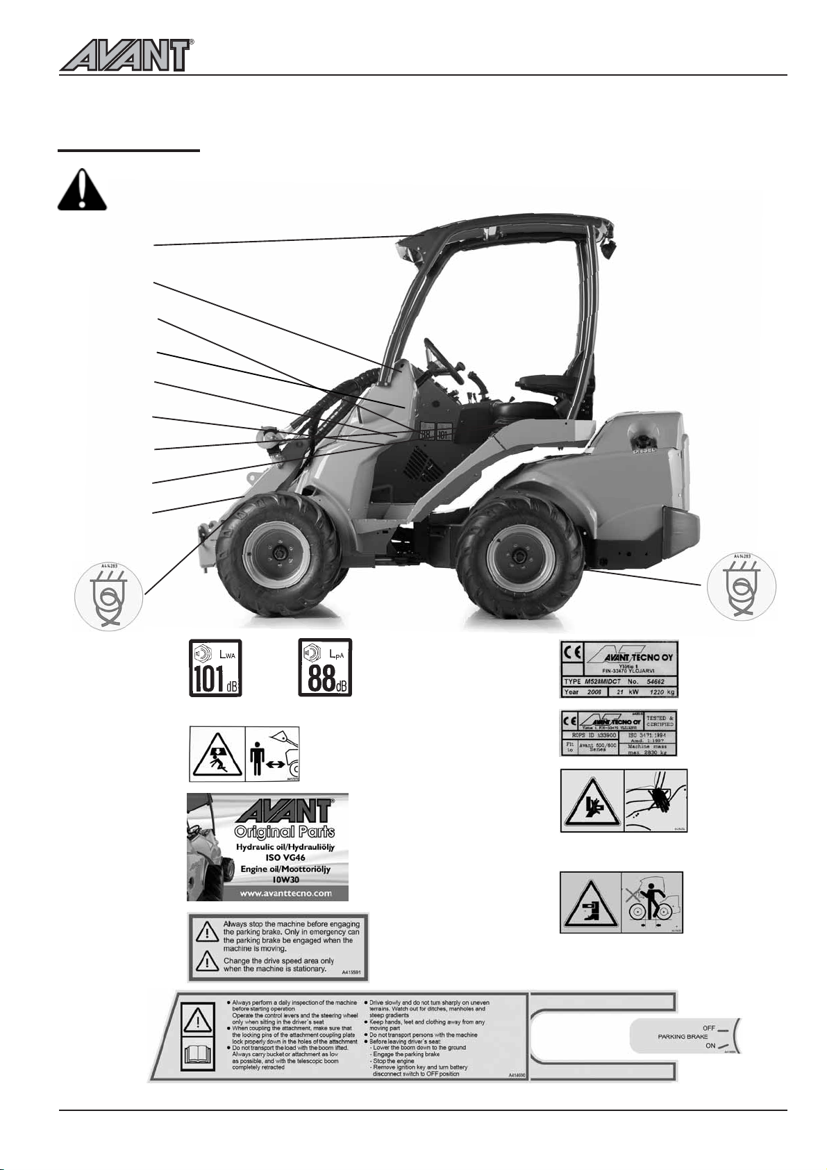
Signs and decals
Make sure that the following signs and decals clean, undamaged and readable. If any of these
decals is missing or is unreadable it should be replaced without delay. Ask for new decals
from your local Avant dealer.
o
n
j
r
l
m
p
500 Series
Description of the loader
q
k
j
k
l
A411047
Sound power level / Sound pressure level at drivers seat
Keep out from the danger zone of
the machine 2 pcs
A417273
A43600
n
o
p
A411456
Risk of crushing, keep hands and feet within
the drivers area
m
r
A415591
q
A411455
Risk of crushing, do not grip the steering
wheel from outside the machine or when
getting into the drivers seat.
A414690
A414664
9
Page 10
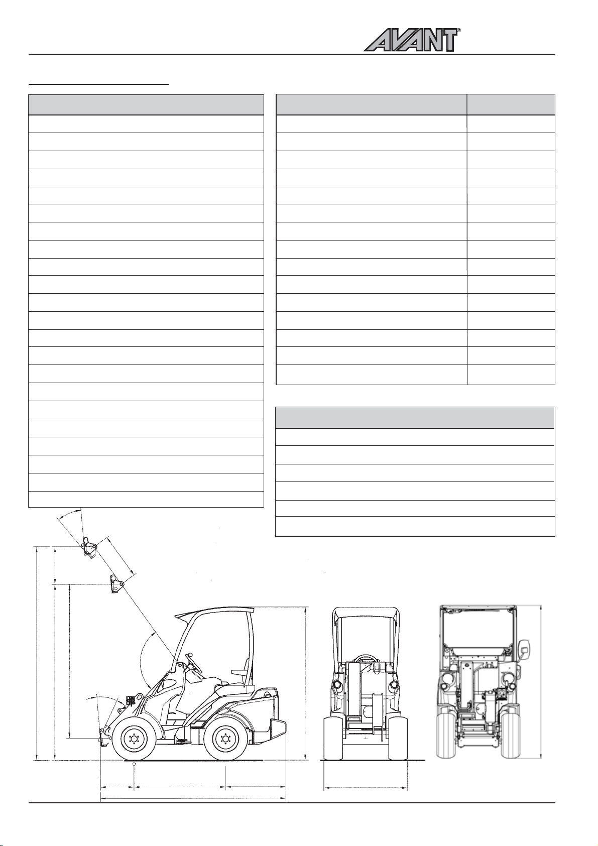
Description of the loader
Technical specification
500 Series
Model
Length
AVANT 520/528
2420/2550 mm
Width (with 23x10.50-12 wheels)
Height (with 23x10.50-12 wheels)
Ground clearance
Weight, starting from
Standard wheels
23x10.50-12
200 - 235 mm
1350/1400 kg
Drive speed
Transmission, drive
Hydraulic oil tank capacity
Auxiliary hydraulics
AVANT 520: 31 l/min 185 bar
AVANT 528: 36 l/min 200 bar
Turning radius inside/outside
995 / 2050 mm
Max. lifting height (with telescopic boom)
with 23x10.50-12 wheels
with 26x12.00-12 wheels
Max. pulling force
Max. lifting capacity (hydr.)
Max. breakout force / 50 cm
(depending on model)
1350/1500 kg
1100/1250 kg
Sound pressure level 2000/14/EC Lp
Sound power level 2000/14/EC Lw
100/96 dB (A)
Hand-arm vibration, total
Whole-body vibration, max.
35°
1130 mm
1985 mm
grass/TR
10 km/h
hydrostatic
38 l
2790 mm
2820 mm
700/750 kp
87/81 dB (A)
< 2,5 m/s
< 0,5 m/s
Model
Engine make & type
Function
Cooling system
Number of cylinders
Starter
Bore * stroke
Displacement
Max. output (ISO Gross)
14 kW (20 hp)
Fuel
Fuel tank capacity
Engine oil type
Viscosity
Engine oil capacity
Charging current max.
Battery
Tipping load, see diagram on page 11.
Tyr e
27 x 8.50-15
23x8.50-12
23x10.50-12
²
26x12.00-12
²
320/60-12
26.5x14.00-12
Part no.
65414 TR
65995 TR
65994 Grass
65997 TR
65996 Grass
65739 TR
65212 Grass
65224 TR
65787 Grass
AVANT 520
Kubota D 722
4 stroke
water
3
electric
67 * 68 mm
719 cm
³
diesel
20 l
API CC
SAE 10W-30
3,8 l
40 A
12V 60Ah
Tyre pressure
2,5 bar
2,0 bar
2,0 bar
2,0 bar
2,0 bar
2,0 bar
AVANT 528
Kubota D 1105
4 stroke
water
3
electric
78,0 * 78,4 mm
1124 cm
³
19 kW (26 hp)
diesel
30 l
API CC
SAE 10W-30
5,1l
40 A
12V 60Ah
Machine width
1030 mm
1080 mm
1130 mm
1290 mm
1290 mm
1480 mm*)
485
2050
2790 - 2820
2305 - 2335
600
100°
35°
430 1200 790/920
2420/2550
*) Requires spacer kit A418958 on the machine
(4 pcs 40 mm spacers, 5-bolt, part. no A417486)
1985 - 2020
Cabs
1030 - 1480
10
LX 2010 - 2038
DLX 2030 - 2118
Page 11
500 Series
Description of the loader
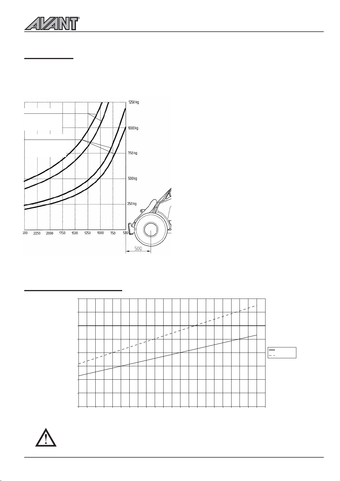
Load diagram
The lifting capacity of the loader is limited by the possibility of tipping around the front axle. The diagram
below shows the tipping loads and max. allowed loads in different loading situations on an even level surface
with the loader chassis in maximum articulation.
Tipping load with the loader
in max. articulation
Rear weight 170 kg
Driver 75 kg
Max. load, ISO 14397-1
The loader in max. articulation
Rear weight 170 kg
Driver 75 kg
Distance from front axle mm
528 520
528
520
The diagrams can be interpreted as follows:
The diagrams show tipping load and max. load with
the load at different distances
from the front axle of the loader
Example: If the center of gravity of the load is
750 mm in front of the front axle, max. load is about
700 kg(520) and 820 kg(528) with a driver weighing
75 kg and with the 170 kg integrated rear weight
mounted on the loader.
NOTICE: If the driver leaves the machine, tipping
and max. loads are reduced respectively.
Tipping load and max. load depend both on the
weight of the driver and the eventual extra weights
mounted on the loader.
Please note that the diagrams are based on the
machine operating on a level, even and firm
supporting ground. Loads should be significantly
reduced when operating on gradients and/or on soft
ground.
Read the safety instructions regarding handling of
heavier loads.
AVANT 520/528 load diagram
Auxiliary hydraulics oil flow
40
35
30
25
20
l/min
15
10
5
0
1500
1600
1700
1800
1900
Max. auxiliary hydraulics oil flow can not be used with all attachments. Check correct engine
rpm and auxiliary hydraulics pump configuration for the attachment with the help of this table
and Operators Manual of the attachment.
2000
2100
2200
2300
2400
2500
2600
rpm
2700
2800
2900
3000
3100
3200
3300
3400
3500
Avant 520
Avant 528
3600
11
Page 12
Description of the loader
Transporting instructions and tie down
points
500 Series
Mount the articulation frame lock, shown on page 26,
on the machine during transports. Lower the boom
down and take off battery disconnect switch.
Remember to remove the frame lock after transport!
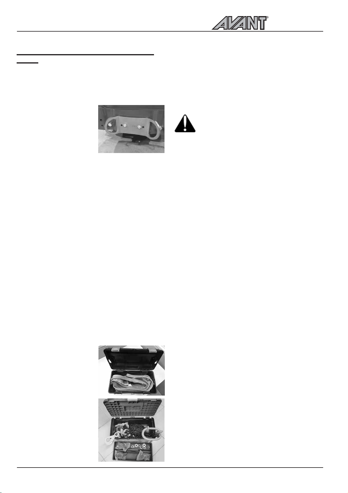
Tie down points are located
on the rear frame on the
sides, and on the front frame
close to the boom. Optionally
available are the rear bumper
and / or behind the rear
wheels installed tie down
brackets (Art. A418746), in which the straps and slings
can be attached.
The loader cannot be towed. It is equipped with
hydrostatic transimission and a hydraulic parking brake
which can be released only when the engine is running
and there is enough pressure in the hydraulic system.
In case there is a technical failure and the engine cannot
be started or doesnt start, the machine must be lifted
e.g. with a forklift truck and transported to service.
The loader can be lifted by mounting appropriate
lifting slings on the ROPS frame or on the cab LX/DLX.
Before lifting, the attachment and eventual extra
weights must be removed. Mount the frame lock on
the machine. Make sure that the lifting slings cannot
move and that the machine doesnt swing during lifting.
Follow the instructions given in the operators manual
of the lifting slings.
Lower the boom and mount the articulation frame
lock as shown on page 26. Remove heavy attachment
and extra counterweights before lifting. Never lift a
loader with persons riding the machine.
Eyelets on extra side counterweights are for
installing or removing the sideweight only.
Never attempt to lift the loader from the
counterweigths or use them as tie-down
points.
Lift a loader with ROPS frame with four straps or
slings approved for lifting and minimum 2 metres in
length. Loop the lifting straps around the four ROPS
posts. To lift a loader with cab LX or DLX, four
appropriate lifting eyelets must be mounted and hooks
and chains are required.
Lifting kit A418706 includes
all necessary parts to lift a
loader with ROPS frame.
Kit A417352 to lift a loader
with cab LX/DLX with
detailed instructions included.
12
Page 13

500 Series
Operating instructions
Operating instructions
13
Page 14
Operating instructions
Operating controls
500 Series
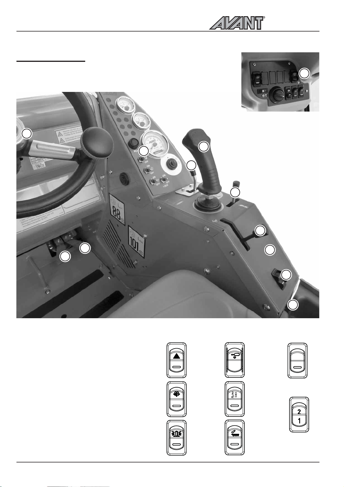
Following picture shows the location of operating controls. The location and
function of controls may be slightly different in different models, see following
pages.
1
10
5
7
11
There is a panel in cab DLX,
up to the right, with the
following switches: parking
brake, heater fan, hydraulic
attachment coupling plate,
emergency blinkers, beacon.
8
6
3
2
1. Steering wheel
2. Drive pedal, left: drive backward (page 16)
3. Drive pedal, right: drive forward (page 16)
4. Parking brake Switch (page 19)
5. Control lever of boom and bucket (page 15)
6. Hand throttle lever (page 15)
7. Auxiliary hydraulics control lever (page 15)
8. Control lever of telescopic boom (page 15)
9. 12 V outlet
10. Dashboard (page 16)
11. Switches on the panel
Emergency
blinker
(option)
Windscreen
wiper and
washer
(Cab option)
11
4
9
Hydraulic
quick
attachment
(option)
Work light
(option)
Hydraulic
rear lift
(Option 528)
14
Beacon
(option)
Floating,
hydraulic
rear lift
(Option 528)
Front/rear auxi-
liary hydraulics
selector switch
(option)
Page 15
500 Series
Operating instructions
Control of loader boom, attachments and other functions
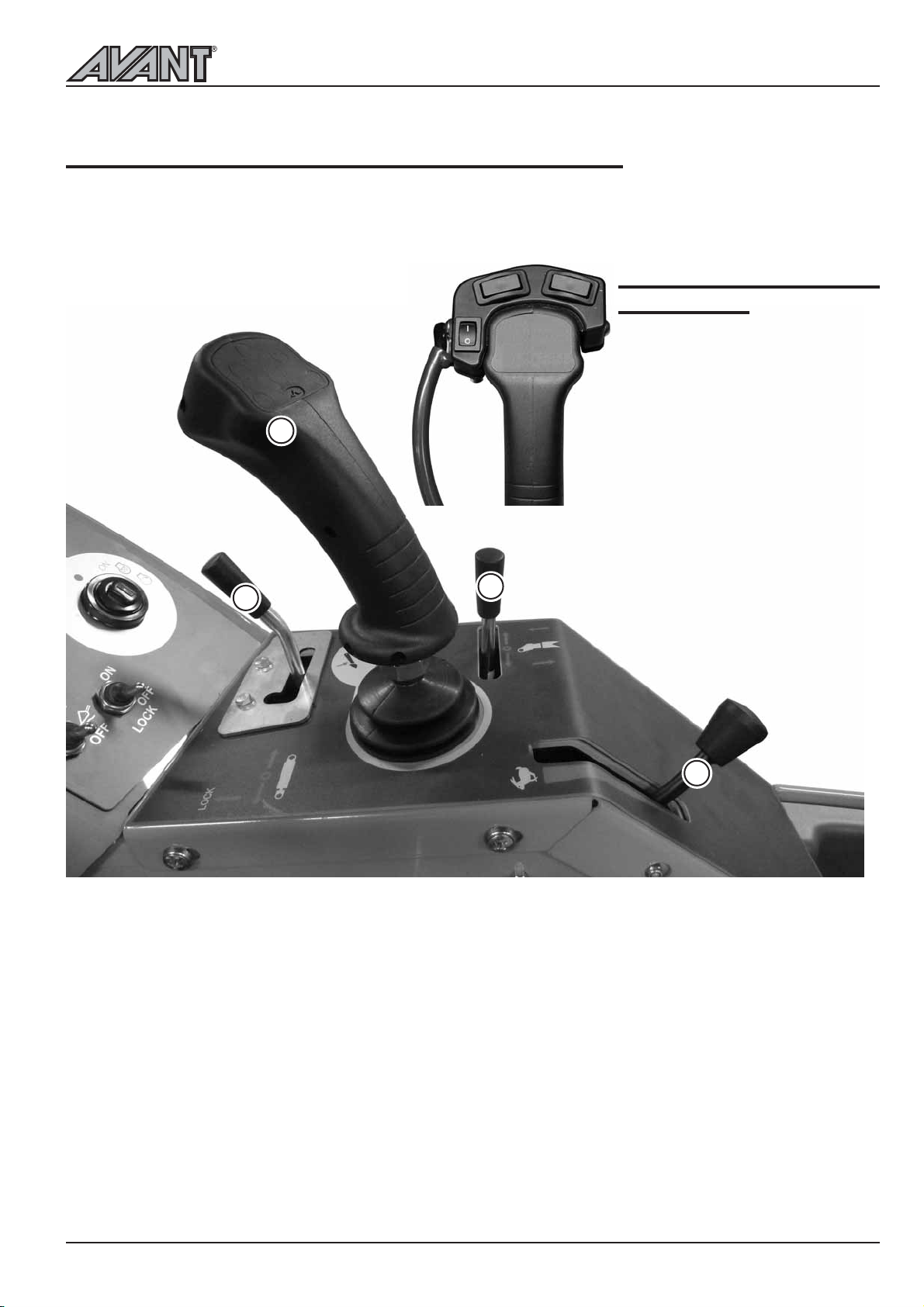
Most of the functions of the loader are controlled at the control panel on the right side of the operator: Boom
and bucket movements, auxiliary hydraulics (attachments), engine revs etc. , depending on loader model.
Following pictures show the different functions:
Attachment control switch
pack (option)
Optional extra with which electric
functions of the attachment are
controlled
Consists of 3 pcs control switches,
wiring and a 7-pole socket which
5
7
8
mounts on the auxiliary hydraulics
multi connector (see page 8). The
corresponding socket of the
attachment electric wire is
mounted on the attachment multi
connector. This way both the
electric wire and the hydraulic
hoses of the attachments are
connected at the same time with
the multi connector.
The switches mount on the boom
control lever and are operated
with the right hand thumb.
5. Control lever of boom and bucket
Pull backward to lift the boom
Push forward to lower the boom
Push left to raise the tip of the bucket (filling)
Push right to lower the tip of the bucket (emptying)
6. Hand throttle lever
Push forward to increase engine revs
Pull backward to reduce engine revs
6
7. Control lever of auxiliary hydraulics
(hydraulically operated attachments)
Push right - move the lever carefully to see which
way the hydraulic attachment moves.
Push left: the attachment moves in opposite
direction
Locking position (on the left): Continuous oil
flow to the attachment.
8. Control lever of telescopic boom
Push right to extend the boom
Push left to retract the boom
15
Page 16
Operating instructions
Dashboard
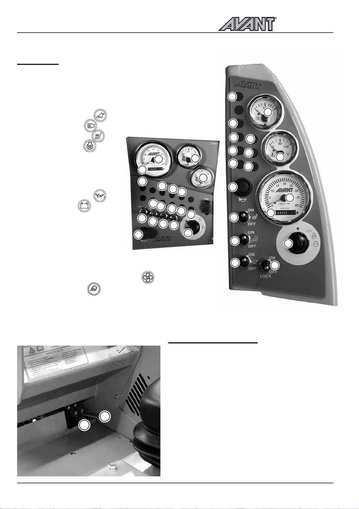
On the dashoard on the right side of the drivers seat
are mounted gauges, indicators and switches which
help the operator to control the loader.
Dashboard may be slightly different in different models.
Following picture shows the different functions:
2. Boom floating indicator
3. Headlights indicator
4. Seat heater indicator
5. Glow plug indicator
6. Fuel gauge
7. Work light switch
8. Tachometer
9. Hour meter
10. Oil pressure indicator
11. Charge indicator
12. Thermometer
13. Ignition switch
14. Signal horn
14
15. Seat heater switch
16. Drive release valve switch
17. Boom floating switch (optional extra)
18. Hydraulic cooler blower fuse indicator
19. Work light indicator
LX/DLX cab
9
1
2
16
17
8
3
19
7
18
4
15
10
500 Series
18
6
2
4
5
3
12
6
5
11
13
19
14
15
10
11
7
17
12
8
9
13
16
Controls in the footwell
Following picture shows the controls located in the
footwell
1. Drive pedal, left: drive backward
2. Drive pedal, right: drive forward
2
1
See correct operation of drive pedals on page 20.
16
Page 17
500 Series
Operating instructions
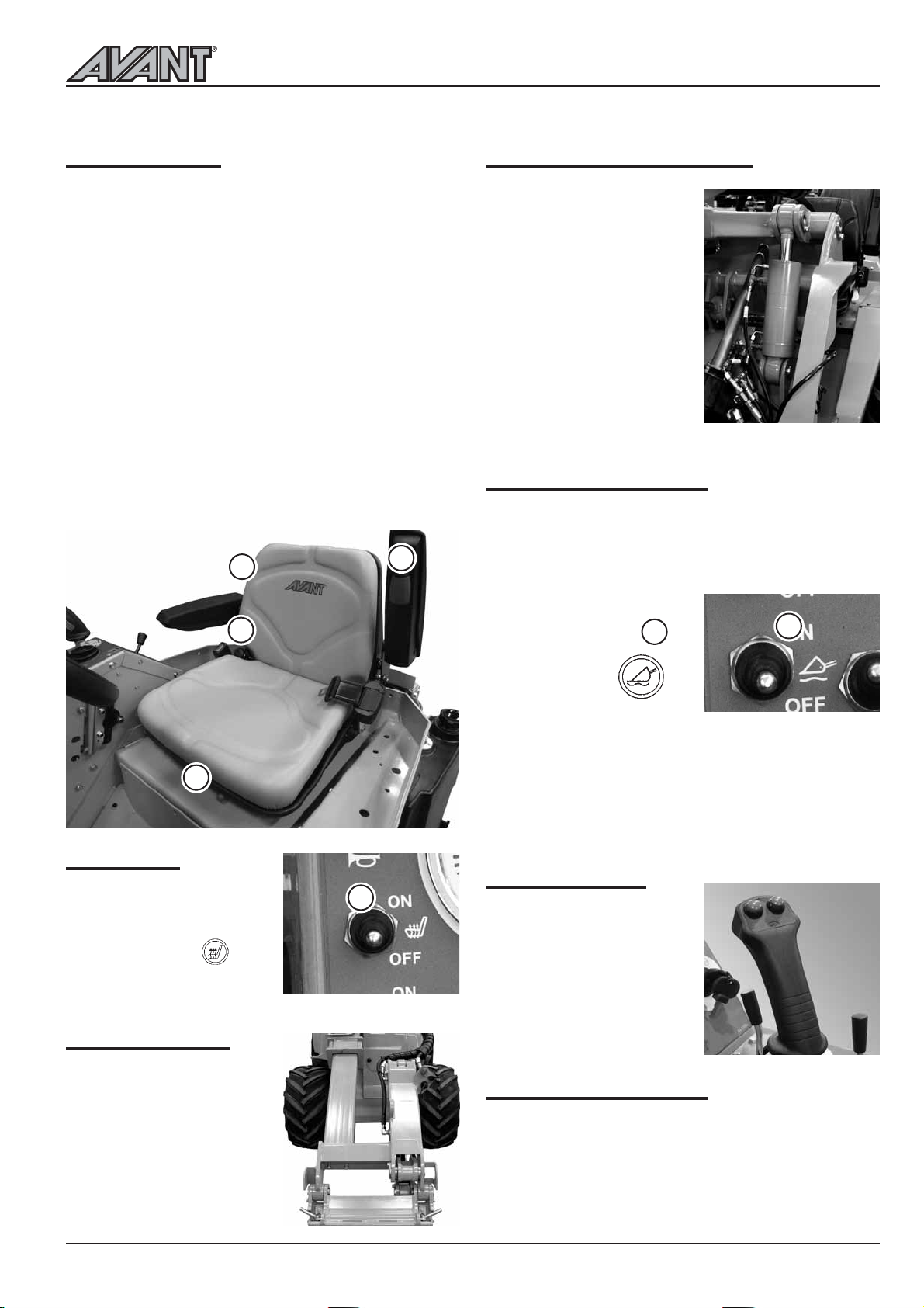
Suspension seat
The optional suspension seat is equipped with a seat
belt and has the following adjustments:
1. Suspension adjustment
by turning the knob counterclockwise suspension
gets harder, by turning it clockwise the
suspension gets softer
2. Angle of the back rest
the angle of the back rest can be adjusted by
pulling the lever
3. Seat position
the distance of the seat from the steering wheel
can be adjusted with the lever which is located
under the front edge of the seat
4. Arm rest angle adjustment
the angle of the arm rest can be adjusted by
turning the roller under the arm rest
Suspension seat can be equipped with a seat belt.
1
2
3
4
Seat heater
The suspension seat is
equipped with an electric seat
heater. Seat heater switch
(15) and indicator are
located on the dashboard.
15
Boom self levelling (option)
Self levelling system keeps the
position of the attachment
the same in relation to the
ground, regardless of the
position of the boom.
Self levelling is hydraulic: there
is a levelling cylinder on the
left side of the boom which
follows the movements of the
bucket tilt cylinder and keeps
the attachment level.
Self levelling is disabled when
the boom floating is switched
on.
Boom floating (option)
The floating system releases the lift cylinder, so that
the boom floats upwards from the position where it
is when boom floating is switched on, allowing the
attachment to follow the contours of the terrain.
1. Lower the boom down
2. Switch on the floating with
rocker switch no.
3. Boom floating indicator on
the dashboard
lights up
When boom floating is being
used, it is possible that air gets
in the hydraulic system. This can lead to inaccurate
boom movements and the boom can give in. Therefore
the boom and attachment coupling plate should always
be moved to extreme end positions after switching
off boom floating. Use boom floating only when
necessary.
17
17
Joystick (option)
The loader can be equipped,
as an option, with a joystick,
where the operation of
auxiliary hydraulics is electric.
Telescopic boom
Telescopic boom is operated
with the control lever no. 8
on the control panel (see page
15).
Length of the telescope is 600
mm and additional lifting
height is 485 mm.
push the buttons to engage
and disengage auxiliary
hydraulics
Work light kit (option)
The loader can be equipped with extra work lights,
making it easier to work in low light. The lights are
operated with the switch on the control panel (see
page 14).
17
Page 18
Operating instructions
500 Series
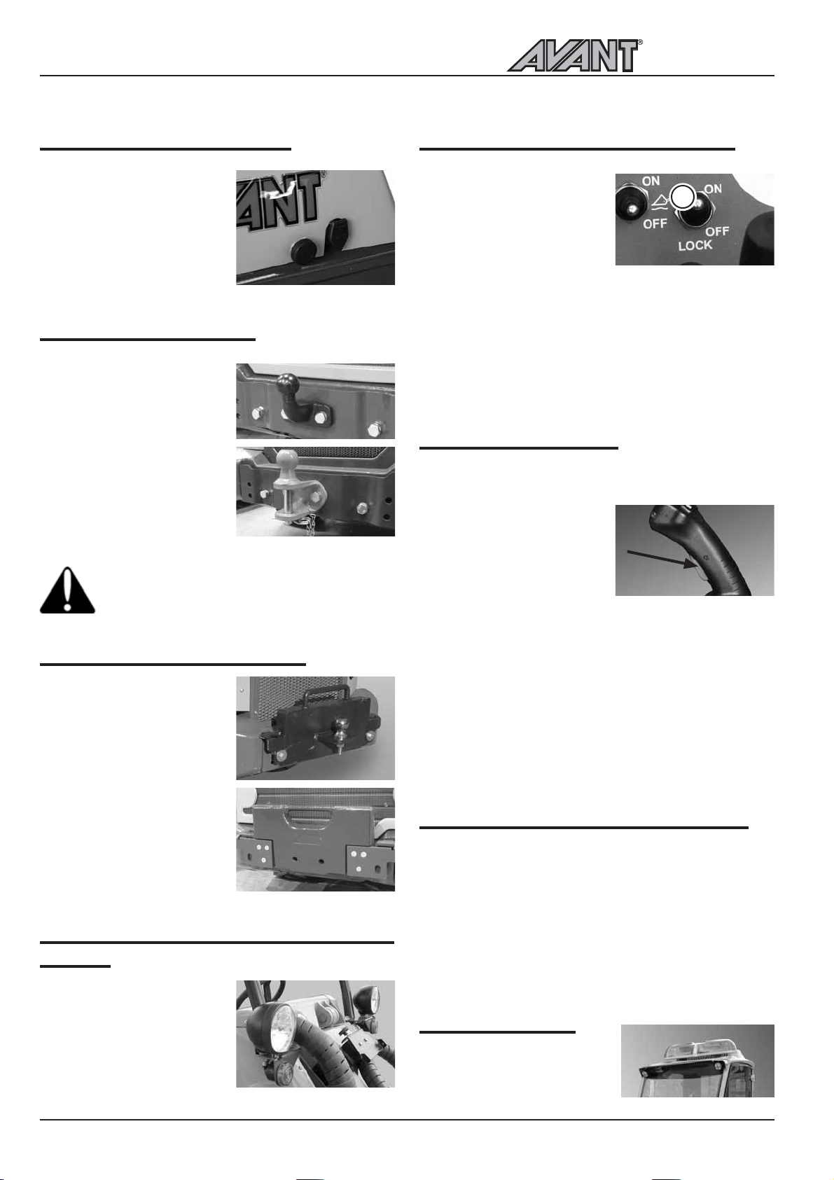
Engine block heater (option)
The loader can be equipped,
as an option, with an engine
block heater. Engine block
heater outlet is on the right
side in the rear of the
machine.
Trailer coupling (option)
The loader can be equipped,
as an option, with a trailer
coupling. There are two types
available: a 50 mm ball hitch
and a 50 mm ball hitch with
towing pin. Both can be
mounted either directly on
the rear bumper or on the
extra back weight.
Max. allowed vertical load of
the trailer coupling is 6900 N,
max. towing load is 6000 N.
Make sure that the weight on the trailer is
distributed correctly so that the trailer cannot
cause an upward lifting force on the trailer
coupling
Extra counterweights (option)
The loader can be equipped
with extra counterweights
that are mounted on the rear
bumper. Max. amount of
extra weights (29 kg/pcs) is
3 pcs. If the machine is fitted
with an extra weight with
trailer coupling, max. amount
of extra weights is 1 pcs.
In addition, extra side weight
kits (80 kg for Avant 520 and
528, 180 kg for Avant 528)
are available as an option.
Headlight, beacon, blinker & reflector kit
(option)
This optional equipment
enables road traffic
registration in certain
countries. Requirements vary
in different countries, please
consult your local AVANT
distributor.
Drive circuit release switch (option)
The switch no. 16, LOCK,
controls a valve which diverts
the oil flow between the left
and right side hydraulic
motors, and this has an effect
on the pulling force.
LOCK OFF: In this mode hydraulic oil flows in series
from motor to motor. The wheels roll freely and the
loader leaves less tire marks on soft and sensitive
surfaces.
LOCK ON: In this mode hydraulic oil flows in parallel
between the hydraulic motors on each side, similar
to a differential lock in operation. This improves
traction and towing capacity of the loader.
16
Anti slip valve (option)
The valve positively diverts oil flow between the right
and left side hydraulic motors
and improves traction on
slippery and uneven surfaces.
It is engaged by pressing
continuously on the switch
on the joystick. As soon as
the switch is released, anti
slip valve is released.
The function of the anti slip valve depends also on the
position of the drive circuit release switch no. 16:
LOCK ON : Anti slip valve diverts oil flow between
all four hydraulic motors - all four wheels have best
possible traction. Use sufficient engine revs and press
properly on the drive pedal.
LOCK OFF: Drive circuit released anti slip valve
diverts the oil flow between the front left and right
hydraulic motor only, not the rear hydraulic motors.
Location of battery disconnect switch
The loader is equipped with a battery disconnect
switch. The switch is located in the rear of the machine,
on the right side (see picture). Battery disconnect
switch cuts the current between battery and the rest
of the electric system. Always switch off main current
when the loader is not used for a longer period of
time, or when servicing the machine. Switch off the
main current in order that the battery doesnt get
empty.
Light bar (option)
Flashing lights on the light bar,
only available on DLX cab.
18
Page 19
500 Series
Operating instructions
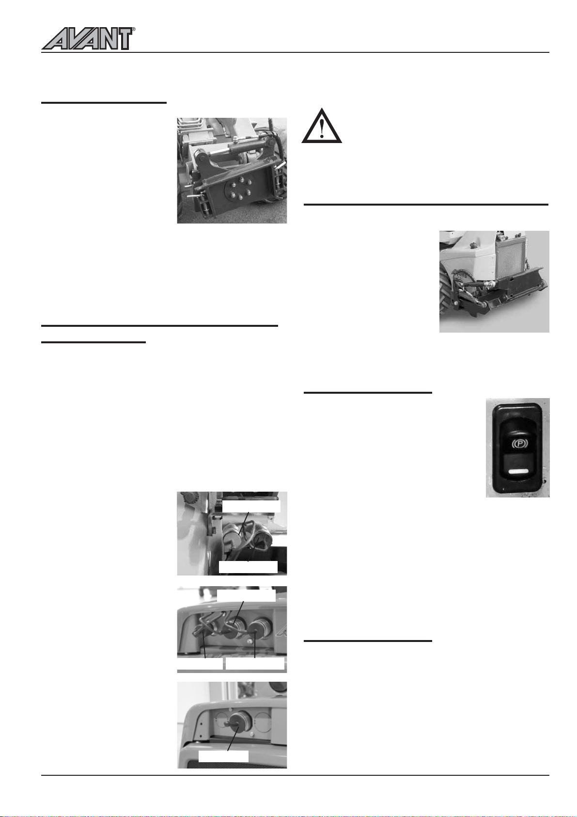
Tilt adapter (option)
The hydraulic tilt adapter
mounts between the
attachment and the
attachment coupling plate. It
allows the driver to tilt the
attachment sideways 12,5
degrees to both directions
from the drivers seat. Tilt
adapter is intended mainly for
non-hydraulic attachments,
but with the optional double acting extra auxiliary
hydraulics outlet in the front (A35884) it is possible
to mount a hydraulically operated attachment (e.g. a
4 in 1 bucket) at the same time. Tilt adapter is operated
with the auxiliary hydraulics control lever (no. 7, page
15).
Extra auxiliary hydraulics outlets, front
and rear (option)
In addition to the standard auxiliary hydraulics outlet,
the loader can be equipped with a double acting extra
outlet. The extra hydraulic outlet can be fitted either
to the front of the loader or to the rear, and the
couplers are conventional type quick couplers. The
installed extra outlet is selected with the rocker switch
on the dashboard (see page 14) and controlled with
the auxiliary hydraulics control lever no. 7 (see page
15).
The loader can be equipped with either the rear
hydraulics outlet or with the extra front outlet but
not with both.
1. Extra auxiliary hydraulics
in the front
Quick couplers are
located under the multi
connector
2. Quick couplers in the rear
Quick couplers are
located on top of the
radiator.
Pressure 2
Pressure 1
Pressure 2
ATTENTION! Before connecting hydraulic
hoses on the rear/front outlet always stop
the engine first and release the pressure in
auxiliary hydraulics line by moving the
auxiliary hydraulics control lever (no. 7,
page 15), or with the buttons of the optional
joystick (page 17).
Hydraulic lifting device in the rear (option 528)
The hydraulic rear lifting device allows mounting of
some attachments on the rear
of the machine, for example
a sand spreader or a rotary
hoe. This means that it is
possible to mount a bucket
or a dozer blade at the same
time in the front.
Hydraulic Rear lifing device
comes with a double acting
auxiliary hydraulics outlet.
Rear lifting device is available only for Avant 528, not
for Avant 520.
Parking brake switch
Avant 500 series loaders are equipped
with a hydraulic parking brake. It locks
the front wheels. Parking brake is
operated with the switch on the control
panel right (see page 14 & 23). A red
indicator on the switch lights up when
parking brake is engaged. The green
backlight under the "P" is lit all the time.
Parking brake engages automatically when the engine
is stopped. The brake can be released only when the
engine is running and there is hydraulic pressure in
the system.
ATTENTION! Never engage the parking brake when
the machine is moving. If the parking brake is engaged
when the machine is moving the brake plates in the
front drive motors will be damaged. Always stop the
machine before engaging the brake.
Snow chains (option)
Double acting outlet
Single acting outlet
Tank line
Pressure
Pressure 1
The loader can be equipped with snow chains, following
tyre size:
23 x 8.50-12 snow chain part no. 64746
23 x 10.50-12 snow chain part no. 64745
26 x 12.00-12 snow chain part no. 64973
320/60-12 snow chain part no. 65603
27x8.50-15 snow chain part no. 65723
19
Page 20
Operating instructions
500 Series
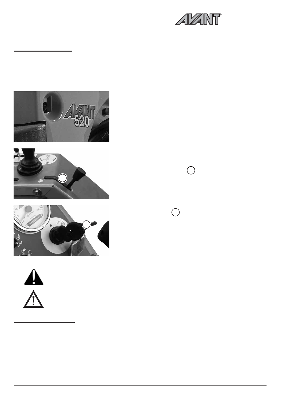
Starting the engine
Before starting the engine do the daily checks, see page 27. Adjust the seat and mirrors (if fitted) so that you
have a good working position and unrestricted field of vision from the drivers seat. Check that all controls
function correctly. See to it that the operating area is safe. Read and follow operating and safety instructions.
1. Turn the battery disconnect switch to ON
3. Move the hand throttle lever to approximately ¼ throttle
1
2
If auxiliary hydraulics is switched on during starting and there is a hydraulically operated
attachment on the machine, the attachment can move suddenly and cause a dangerous
situation. Make sure that the auxiliary hydraulics control lever is in neutral position during
starting.
The engine cannot start if auxiliary hydraulics control lever (no. 7, page 15) is in locking position
4. Make sure that auxiliary hydraulics is switched off (lever in
neutral position). Do not press on the drive pedals.
5. Turn the ignition key to the right.
6. Turn the ignition key further to the right until the engine
starts, then release the chocke button.
If the engine doesnt start, do not try to start longer than 10
seconds at a time. Make sure that there is diesel in the tank,
wait a little and try to start again.
2
1
Stopping the engine
1. Lower the boom down, reduce engine revs, stop the attachment (move auxiliary hydraulics control lever
to neutral position, see page 15)
2. Stop the engine by turning the ignition key to the OFF position (to the left)
3. Release auxiliary hydraulics pressure (see page 15).
4. Prevent unauthorized use of the loader. Take off the ignition switch and turn the power off with the battery
disconnect switch.
20
Page 21
Drive control
500 Series
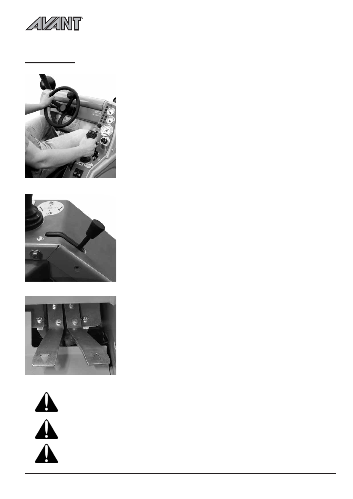
AVANT 500 series loaders are equipped with a hydrostatic drive system,
there is a variable displacement hydraulic pump in the drive circuit. The
oil flow of this drive pump is steplessly adjusted with the two drive pedals.
The drive pedals act in a proportional way to control the drive speed and
power available at the drive motors.
This hydrostatic driving system has different operating characteristics to
a mechanical drive. To get maximum pushing power push the pedals lightly
for higher travel speed push the pedal harder.
When thinking about the function of the two drive pedals, they should be
compared to gears, not to a conventional throttle pedal. The drive pedal
in a way shifts on a higher gear the more the pedal is pressed. Therefore
you shouldnt press the pedal more when the engine starts to struggle.
Pressing the pedal just causes the engine to stop.
When you want to have a high pulling force:
1. Use high engine revs
2. Select a relatively slow drive speed with the drive pedal. That is: press
Operating instructions
the pedal only lightly (= select a low gear). This way the full output of
the hydraulic system and the engine can be taken out.
Driving of the machine is controlled with the drive pedals and hand
throttle as follows:
Select the revs of the engine with the hand throttle lever on the control
panel. The basic rule is: use lower revs for lighter work and higher revs
for hard work. When driving, the revolution speed of the engine can be
adjusted with the hand throttle lever, if necessary. Do not turn the machine
with a high travel speed. Hand throttle also has an effect on the operation
speed of a hydraulically driven attachment: the more throttle the faster the
attachment operates. Make sure not to exceed max. allowed oil flow of
the attachment.
If you want to drive forward, press gently on the right drive pedal until
the machine starts to move slowly. The desired drive speed is selected with
the drive pedal: the more the pedal is pressed the faster you will travel.
When you wish to stop gently release the pedal by lifting of your foot,
and the machine will slow and stop.
Drive backward is controlled with the left drive pedal in the same way as
drive forward: the more the pedal is pressed the faster you will travel.
Familiarise yourself with the driving of the machine on low speed and on
a flat, even and open place where unintended movements dont cause
problems or danger. When you have learned how to drive on low speed,
increase speed gradually and learn how to drive with higher drive speeds.
Make sure that there are no persons in the operating area of the machine.
Hydraulic oil temperature has an effect on the hydrostatic transmission of the loader. When
ambient temperature is below 5º C, let the engine run and the machine warm up properly before
starting to drive. Drive carefully until the machine reaches its normal operating temperature.
When hydraulic oil gets warmer, driving characteristics of the transmission change. When the oil
is warm and hydraulic oil cooler has switched on, stopping distance of the machine can be longer
than normally. If the machine is used constantly in high ambient temperatures, hydraulic oil type
and viscosity must be suitable for these conditions. Contact Avant service.
Should there be a disturbance or malfunction in the hydrostatic transmission and consequently
the braking force is not sufficient, engage the mechanical parking brake. Parking brake can also
be engaged during driving if necessary.
21
Page 22
Operating instructions
500 Series
Steering of the machine
Steering of the machine happens with the steering
wheel. The steering wheel is hydraulically powered.
A practical way of steering is to steer with your left
hand on the knob of the steering wheel. This way
your right hand is free to operate other functions.
Always remember safety first. Test all
the functions of the loader at an open and
safe place. Make sure that there are no
persons in the operating area of the
machine and the danger zone of the
attachment.
When driving, always keep the loader
boom as low as possible. Risk of tipping
over increases considerably when there
is a heavy load on the loader (a heavy
attachment or a big load in the bucket)
and the boom is up when driving.
Never use a high drive speed when turning.
In particular: when the loader boom is up
the stability of the machine is much weaker
when turning.
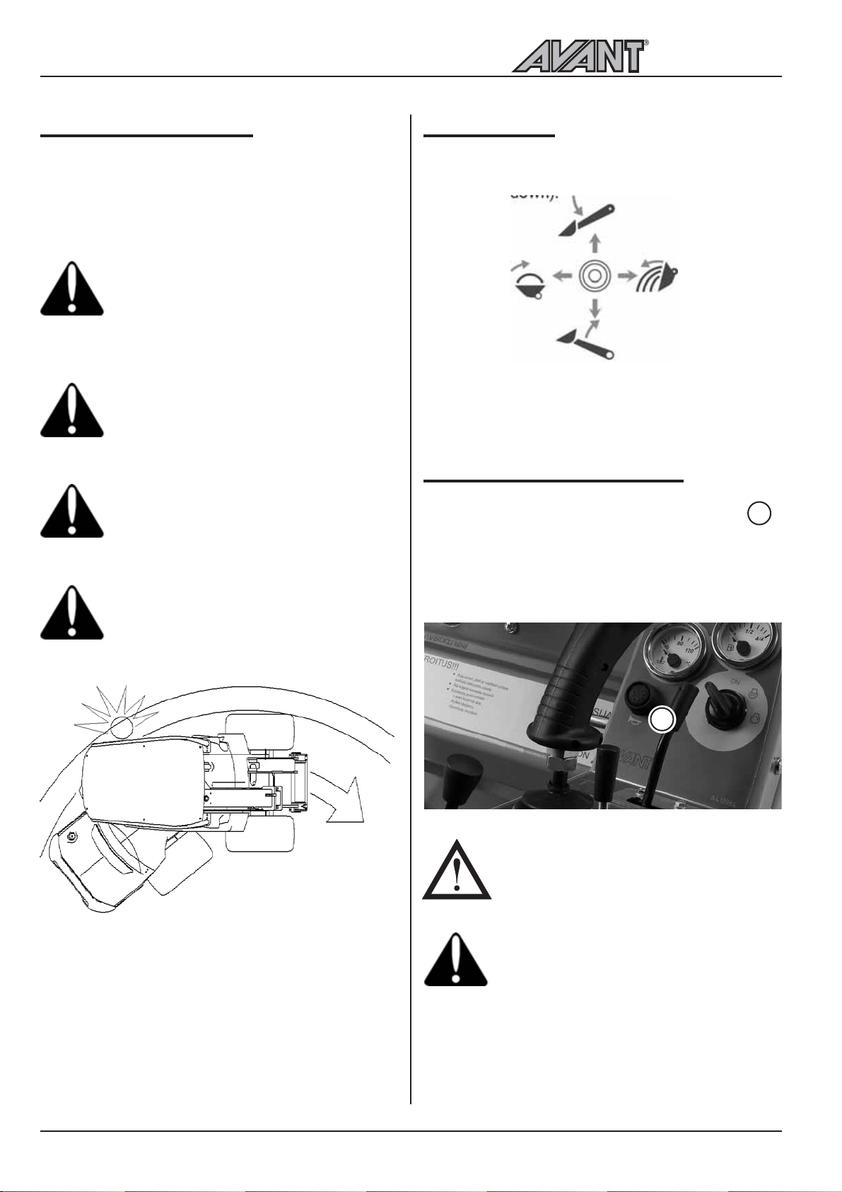
Remember that, when turning, the driver´s
seat extends beyond the turning radius of
the wheels. Stay inside the safety frame
(risk of collision and crushing).
Loader control
The loader boom and bucket are controlled with the
multi-function lever sideways (tilt) and back & forward
(boom up & down).
Pull backward to lift the boom
Push forward to lower the boom
Push left to raise the tip of the bucket (filling)
Push right to lower the tip of the bucket (emptying)
Using the auxiliary hydraulics
Auxiliary hydraulics (hydraulically operated
attachments) are controlled with the lever no.
on the control panel, or with the buttons on the
optional joystick (see page 17). The lever locks in the
locking position (on the left) which facilitates operation
of the attachments that require constant oil flow
(rotary broom, backhoe etc.).
7
Pay attention to other machines and persons that are
moving in the area. Make sure that there are no
persons in the danger zone of the loader and the
attachment. The danger zone of the loader covers
the reach area of the loader boom, the turning area
on the side and in the front and rear of the loader.
Always put down the load when leaving the machine
the loader is not designed to stay with the loader
boom and load lifted. Learn how to operate the loader
in a safe place.
7
NOTICE! The engine cannot start if the
auxiliary hydraulics control lever is in the
locking position.
Going near an attachment that is in
operation can cause a serious risk. Switch
off auxiliary hydraulics before leaving
drivers seat or stopping the engine.
Operate the controls only when sitting in
the drivers seat.
22
Page 23
500 Series
Operating instructions
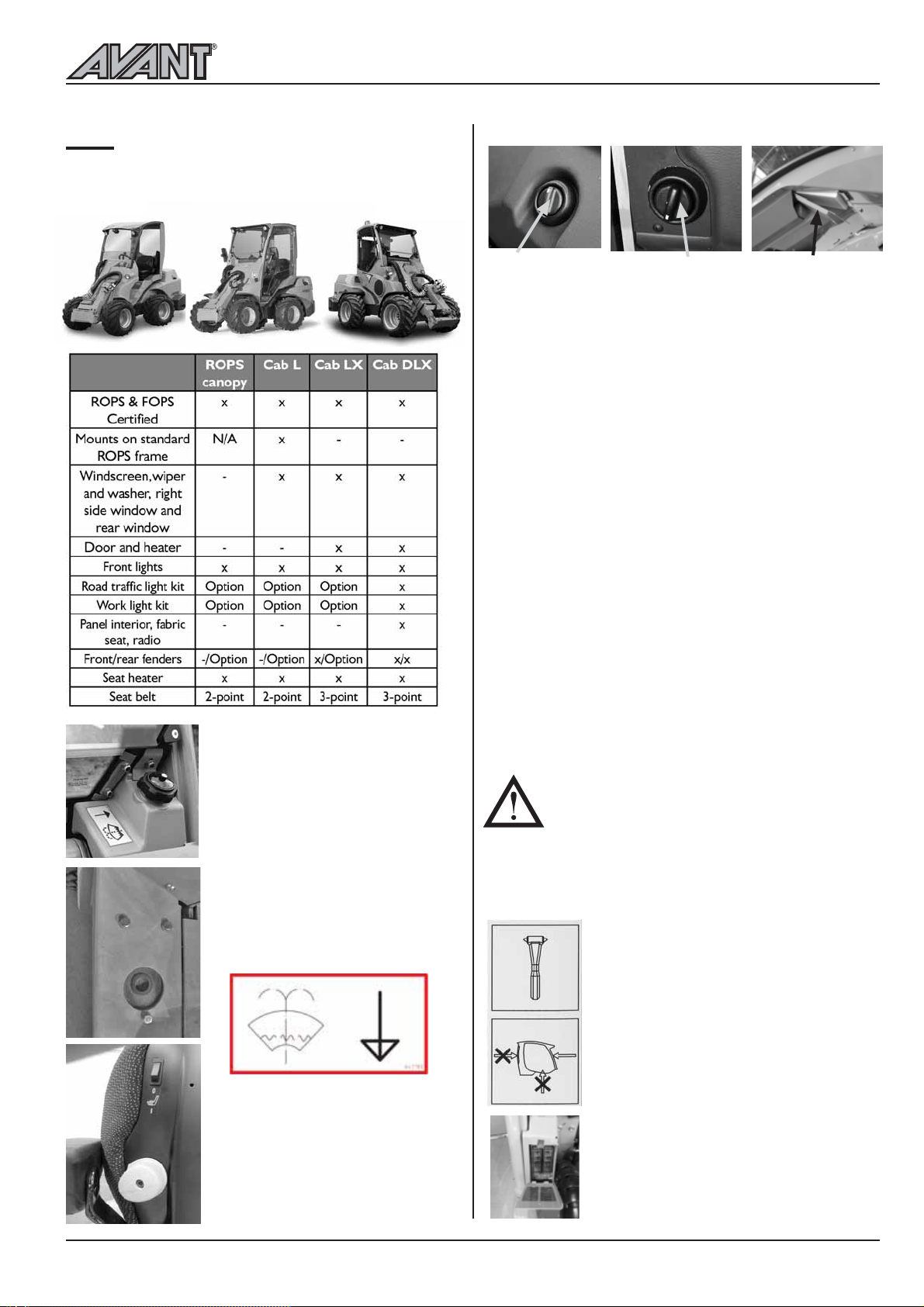
Cabs
AVANT 500 series can be equipped, as an option,
with cab L, LX and DLX. All cabs are ROPS and FOPS
certified.
Windscreen washer tank and filler
cap on machines with cab LX and
DLX are located outside the cab,
in front of the windscreen on the
left.
On machines with cab L the tank
is located behind the front left
wheel and the filler opening is on
the footboard.
The optional air suspension seat
(cab DLX only) is equipped with
heater. Seat heater switch is
located on the back side of the
back rest on the left.
Heater
Temperature
adjustment
Cab LX/DLX is equipped with a warm water heater
which works like a central heating system, circulating
the coolant of the engine. Cab temperature can be
adjusted with the rotary switch of the heater. Air flow
can be directed with the nozzles on the front panel
and in the footwell. Heating efficiency and air flow can
be adjusted with the fan.
The cab is also equipped with an air circulation system:
There is a ventilation hatch below the seat in the
footwell. The hatch is opened and closed with the
lever in the middle. As soon as the hatch is opened
the heating system starts to take warm air from the
cab and circulates it through the nozzles back in the
cab. This way the cab warms up quicker in cold
weather.
NOTICE: Switch off the air circulation as soon
as the temperature in the cab is sufficient,
otherwise moisture starts to condense on the
windows.
The cab is also equipped with a replaceable cab air
filter. The filter cartridge (part no. 65118) can be
changed from outside the cab, under the door on the
left side (see picture above)
Do not drive with the cab door open, nor
turn the steering wheel when the cab door
is open. The door may break.
Do not cover the air vent hole in the cab,
located down in the right rear corner, in
order that moisture does not condense
on the windows.
Safety
Familiarise yourself with the special drive
features and space needs of this
articulated loader, equipped with cab,
on a flat, even and open place.
Remember that, when turning, the cab
extends beyond the turning radius of
the wheels. This should be taken into
consideration especially when driving
in confined spaces, in order that the rear
of the cab will not get damaged.
If necessary, the windscreen can be
broken with the emergency hammer in
the cab. This way it is possible to get out
of the cab in an emergency situation.
The fuse box on machines with cab
LX/DLX is located outside the cab, on
the right side below the windscreen.
Fan (cab LX)
Filter
23
Page 24
Operating instructions
500 Series
Requirements for attachments
Check max. allowed hydraulic oil flow for the attachment. Adjust engine revs so that they are suitable for
the work and the attachment.
Read Operators Manual of the attachment before starting operation. Make sure that the attachment is
compatible with the loader. Contact your Avant dealer if necessary
Make sure that the attachment is connected properly on the attachment coupling plate, and that it is being
used in accordance with the instructions in the Operators Manual. Follow instructions regarding personal
protective equipment and safety distances.
Put the attachment down on the ground and stop the engine before leaving drivers seat. Familiarise yourself
with the operation and stopping of the attachment at a safe place. Follow service instructions.
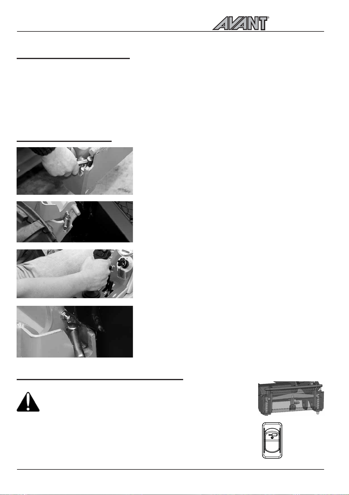
Coupling the attachments
Coupling of the attachments into the attachment coupling plate
happens as follows:
Stage 1 :
Lift up the two locking pins on both sides of the attachment
coupling plate and turn them backward so that they remain in
the up position
Make sure that the pins remain in the up position, otherwise
you cannot couple the attachment properly!
Stage 2 :
Turn the attachment coupling plate with the tilt movement so
that the upper edge of the plate leans forward.
Drive the loader into the attachment
Stage 3 :
Lift the boom a little so that the attachment lifts off of the ground
Pull the boom control lever to the left so that the lower edge
of the attachment coupling plate turns into the attachment
Stage 4 :
Pull the boom control lever more to the left so that attachment
coupling plate turns more and the brackets on the boom push
the pins down in the holes of the attachment.
Make sure that the pins lock properly down in the holes of the
attachment!
Hydraulic attachment coupling plate (option)
Always make sure that the locking pins lock properly down in the holes of
the attachments. Both pins must be locked. Avoid unintentional dropping of
the attachment. Operate the hydraulic coupling only when the attachment
is close to ground.
The hydraulic attachment coupling plate enables coupling and disconnecting of the
attachment from drivers seat. There is a hydraulic cylinder on the attachment coupling
plate which moves the locking pins up and down. The electro-hydraulic system works
also when then engine is not running, as long as the ignition switch is in ON position
(current on). Control switch is located at the control panel on the right (see page 14).
24
Switch up:
Locking released
Switch down:
Locking position
Page 25
500 Series
Operating instructions
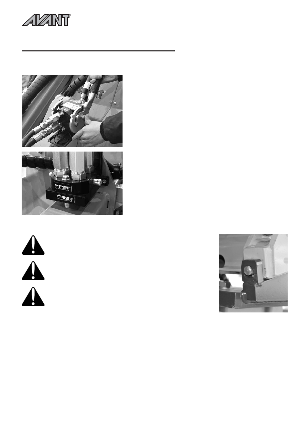
Coupling the hydraulic hoses of the attachment
Hydraulic hoses of the attachment are equipped with the multi connector system, which connects all hoses
at the same time.
Coupling the multi connector
Align the pins of the attachment connector with correspondig
holes of the loader connector. Connecting is not possible if the
multi connector for some reason is mounted in a wrong way on
the attachment hoses. Connect and lock the multiconnector by
turning the lever towards the loader.
The lever should move easily all the way to locking poisition. If
the lever doesnt move easily, check alignment and position of the
attachment and loader side connectors and clean the connectors.
Stop the engine and release pressure in auxiliary hydraulics line
by moving the auxiliary hydraulics control lever in both directions
a couple of times.
Disconnecting the multi connector
Before disconnecting put the attachment down on a solid and
even surface. Switch off auxiliary hydraulics. Disconnect
attachment hoses by pressing on the red button on the
multiconnector and simultaneously turn the lever away from
the machine.
After ending operation put the multi connector on its "parking"
on the attachment.
Make sure that the attachment is properly connected on the
attachment coupling plate. An attachment that comes loose may
tip over or fall on the loader, causing personal injuries.
Do not try to lock the locking pins by using the brackets on the
boom when the attachment is lifted over one metre from the
ground. Lock the locking pins by hand and make sure that both
pins lock properly down in the holes of the attachment.
Always read also the additional instructions for coupling and using
of the attachment in the Operators Manual of the attachment.
25
Page 26
Service and maintenance instructions
500 Series
Service and maintenance instructions
Service parts are available through your Avant dealer or authorized service.
If you are not sure about how to do any service operation, ask for additional information before
starting servicing. Contact Avant service.
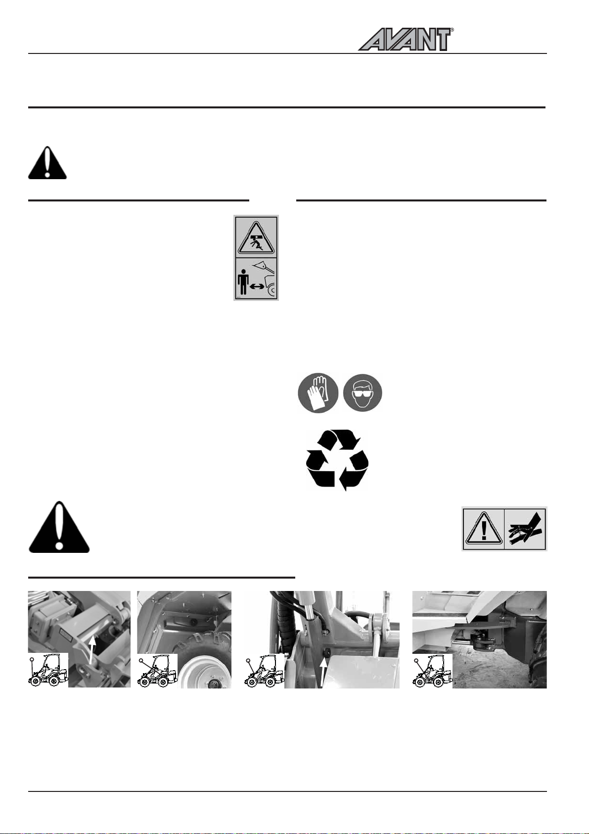
Safety instructions for maintenance
Stop the engine and let it cool down
before starting any service operation.
Put the service support on the boom lift
cylinder when working under the boom.
Install the frame lock when lifting the
machine, for instance when changing tyres
Check hydraulic hoses and components
only when the engine is stopped and hydraulic pressure
is released. Repair all leaks as soon as you have noticed
them, because a small leak can quickly change into a
big one. Do not operate the machine if you have
noticed faults or leaks in hydraulic system. Leaking
hydraulic fluid can cause serious personal injuries and
is harmful to the environment.
Check hydraulic hoses for eventual cracks and wear.
Follow the wear of the hoses and stop operation if
the outer layer of any hose has worn out. If there are
signs of oil leakage, put a piece of cardboard under
the probable leakage place in order to find the leakage.
If you find a fault, the hose or the component must
be replaced. Contact your Avant dealer or service for
spare parts.
Releasing the pressure of hydraulic system
Make sure that there isnt pressure in the hydraulic
system that could cause danger during service
operations.
In order to release the pressure in hydraulic system
stop first the engine and lower the boom down
completely. Move all control levers, including control
lever of telescopic boom and auxiliary hydraulics, to
extreme end positions a couple of times. Remember
that the boom or attachment can move when releasing
the pressure. Move the levers until all movements
have stopped.
Wear protective glasses and gloves
when servicing the machine.
The fluids in the machine are
harmful to the environment. Take
waste oil and fluids to recycling
station.
Never handle pressurized hydraulic components, because ejection of high
pressure hydraulic fluid can cause serious injuries. Do not operate the machine
if you have noticed a fault in the hydraulic system. Consult a doctor immediately
if hydraulic fluid penetrates your skin.
Installing of service support and frame lock
The red service support of the boom lift
cylinder is located at the tip of the boom,
behind the attachment coupling plate. The
frame lock is located over the articulation
joint, under the seat base, and is fastened
with a bolt.
Make sure that the boom stays
up during maintenance operations
by putting the service support on
the lift cylinder piston rod. Secure
the service support by locking it
on the piston rod with the long
screw that is on the support.
The frame can be locked with
the red frame lock. This way
the loader frame stays straight
during e.g. transportation.
Install the frame lock in the
holes on the front and rear
frame and secure it with the
cotter pin.
26
Page 27
Daily inspections
500 Series
Service and maintenance instructions
Tyre pressure
Boom movements
Drive control and steering
Eventual need for lubrication
Cleanliness of engine compartment and radiators
Eventual oil leakages
Locking of attachment and locking pins on
attachment coupling plate, function of attachment,
position of attachment hoses
Condition of the loader, safety frame, seat belt
and other safety equipment
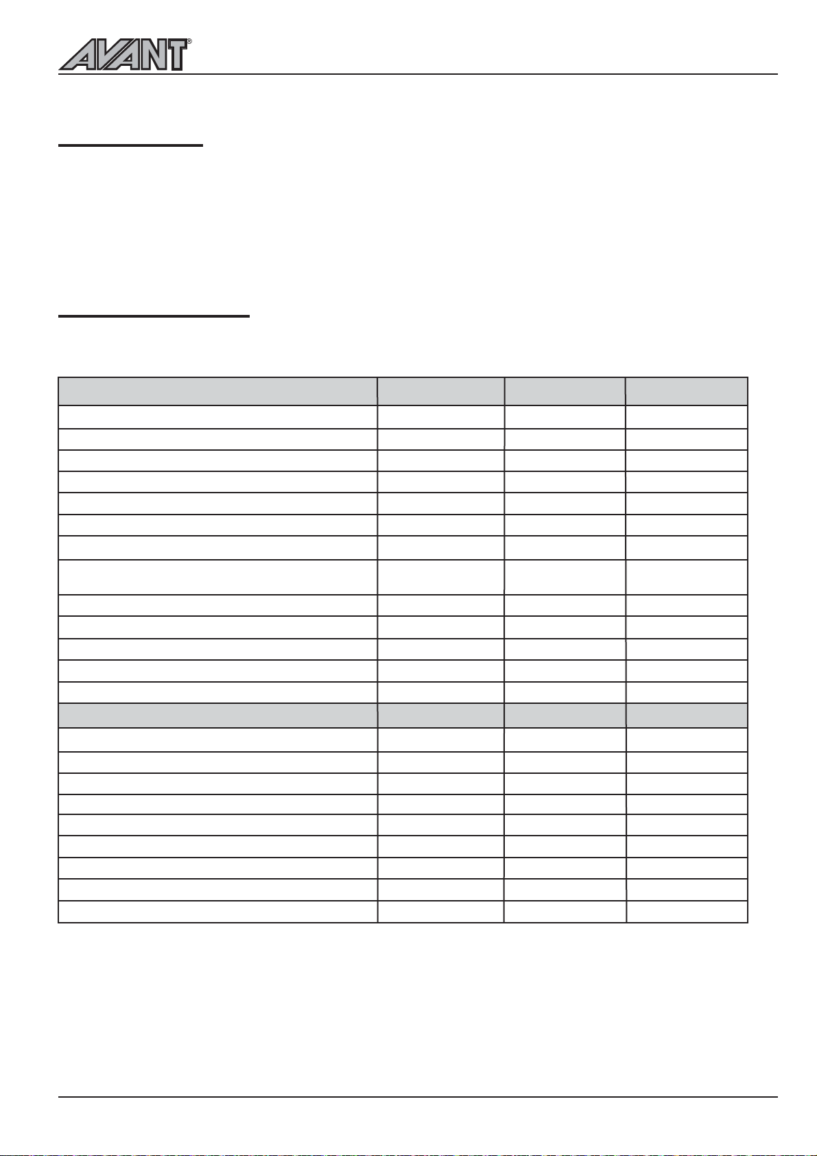
Maintenance schedule
Following table shows the maintenance and service points and intervals. There are more detailed instructions
about each service operation, in numerical order, on the following pages.
Loader
1. Check tyre pressure
2. Clean the machine
3. Grease the machine
4. Check battery
5. Check hydraulic oil level
6. Change hydraulic oil filters
7. Change hydraulic oil
8. Check tightness of bolts, nuts
and hydraulic fittings
9. Check pressure of hydraulic system *)
10. Adjust pressure of hydraulic system *)
11. Check slide pads 1 and 2 on the boom
12. Adjust or change slide pads 1 and 2
13. Check/change slide pads 3, 4, 5, 6, 7 and 8
Every week
n
n
n
l
l
After 50h
ll
ll
l
n
n
n
Every
400 h/year
l
l
n
l
ll
Engine*)
14. Check engine oil level
15. Change engine oil
16.
Check condition and tightness of alternator belt
17. Check water hoses and hose clamps
18. Change engine oil filter
19. Change fuel filter
20. Clean radiator cells
21. Change coolant
22. Change air cleaner element
l Maintenance operation
n When necessary
*)
A 250 bar pressure gauge, equipped with manometer fitting, is required for
checking the pressure of the boom lifting and auxiliary hydraulics.
l
l
l
27
l
ll
l
l
l
l
l
n
l
Page 28
Service and maintenance instructions
500 Series
2. Cleaning of the loader
Cleanliness of the loader is not only a question of
outer appearance. All surfaces, painted and others,
will stay in better condition when they are cleaned
regularly. A clean machine also lasts longer. A dirty
machine will run hotter and will collect dirt into the
air cleaner, which is likely to damage the engine. Pay
special attention to the cleanliness of the engine, the
oil tank cover, the engine compartment and the
hydraulic pump compartment.
The loader can be washed with a pressure washer.
However, avoid direct spraying on hydraulic
components (hoses, cylinders) and decals. After
washing grease all greasing points, also the attachment
coupling plate and locking pins.
The loader is equipped with a hydraulic oil
cooler, which is located in the front frame on
the right side, make sure to clean the oil cooler
cell with compressed air every time you are
servicing the loader - and even more frequently
if the loader is being used in dusty conditions.
Take off the right side cover plate before
cleaning the oil cooler.
3. Greasing of the machine
Greasing of pivot points is very important in order to
avoid wear. Most of the greasing points are on the
loader boom. The picture on page 31 shows the
location of grease nipples.
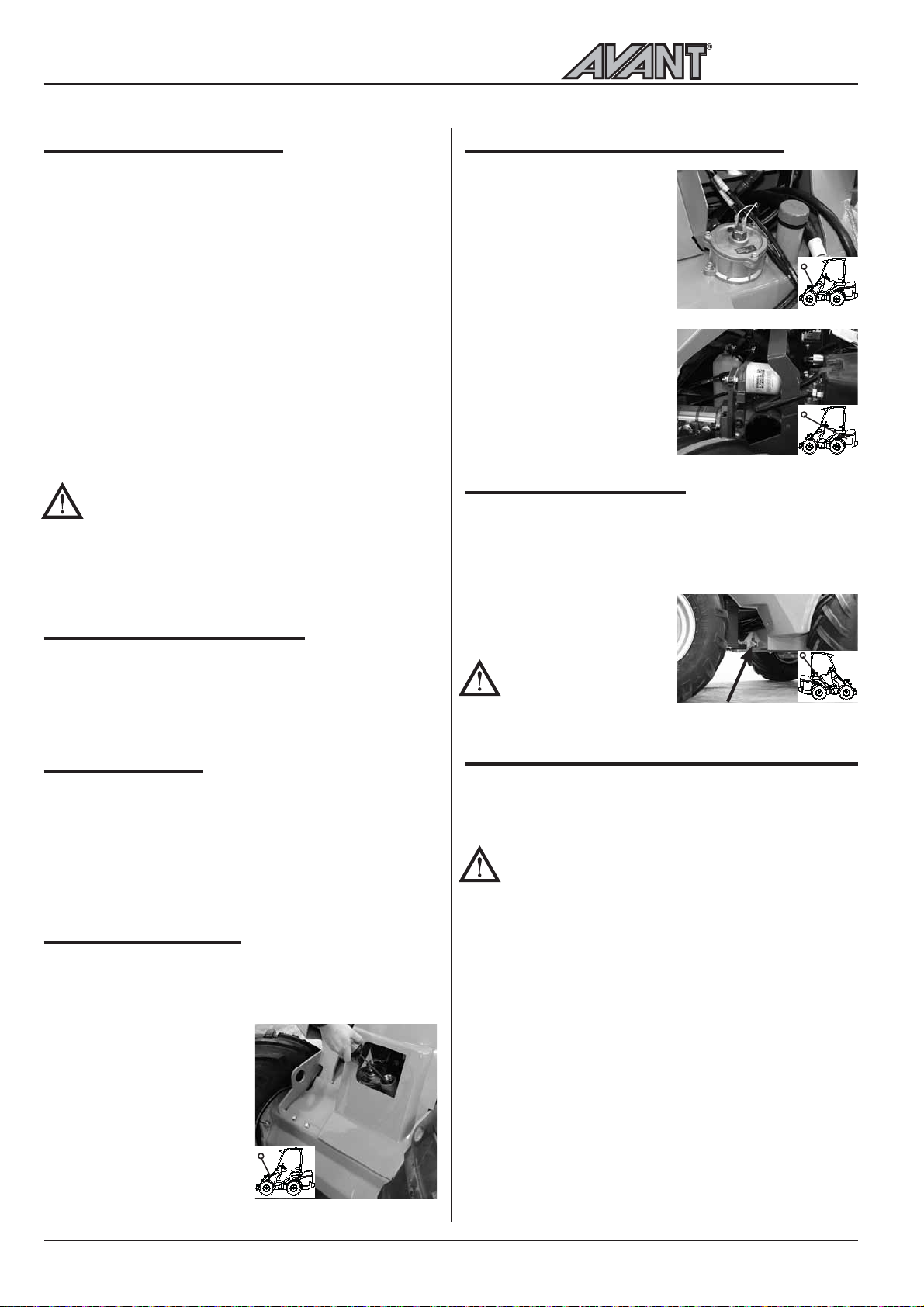
6.Changing of hydraulic oil filters
The hydraulic oil return filter
is located on top of the
hydraulic oil tank, under the
front cover. Take off the
cover and replace the oil
filter cartridge.
Remember to use the
service support (page 26).
The hydraulic pressure filter
is located in the back frame
beside the hydraulic pumps.
When unscrewing the filter
hold the screw in the
housing with a 12 mm allen
key and replace the filter.
7. Hydraulic oil change
When changing hydraulic oil, the oil can be removed
with a suction pump or by opening the drain plug on
the right side of the front frame, next to the articulation
joint. In both cases it is important to clean the magnetic
drain plug. Hydraulic oil tank
capacity is 38 litres. Use ISO
VG-46 certified mineral
hydraulic oil.
Use of synthetic
hydraulic fluids is not
allowed.
4. Battery check
Inspect and clean battery terminals regularly. Check
also condition and fastening of battery cables and
terminal insulators. Make sure that battery cables
cannot chafe against any sharp edges. Check also
condition and fastening of battery disconnect switch
and cables.
5. Hydraulic oil level
Hydraulic oil level can be checked with the dipstick
in the filler. Oil level should be at the lower mark of
the dipstick when the loader boom is up. Refill when
necessary. Do not let any
contaminents enter the
hydraulic oil tank during this
procedure. There is a
breather filter inside the
dipstick cap which should
be cleaned or changed once
a year.
Remember to use the
service support (page
26).
8. Check and tightening of bolts, nuts and fittings
Check tightness of bolts, nuts and hydraulic fittings
regularly.
NOTICE: Tighten wheel nuts after first 5
operating hours. Check tightness of wheel
nuts regularly. Wheel nuts shall first be
tightened to 120 Nm diagonally opposite
and finally tightened to 140 Nm.
28
Page 29
500 Series
Service and maintenance instructions
9. Check pressure of hydraulic system
Pressure checking points for different functions are
as follows:
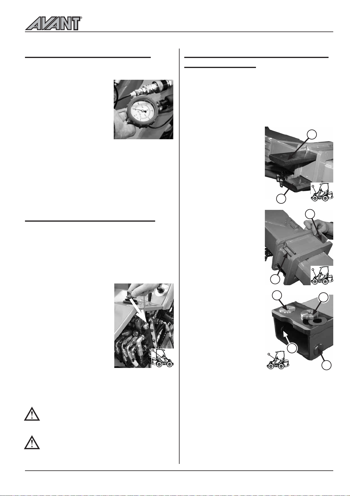
Auxiliary hydraulics: Pressure
is checked from the measuring
point, with full revs and by
turning the aux. hydraulics
control lever. Pressure setting
should be 185 bar for 520 and
200 bar for 528.
Drive pressure: In order to
check the pressure in the drive
circuit one needs to mount a pressure gauge in the
pressure line in each and every case, if pressure seems
to be clearly wrong. There are two pressure relief
cartridges (one for drive forward, one for drive
backward) which have fixed 350 bar pressure setting.
It is recommended pressures should only be
checked by a competent and experienced
technician. Call your AVANT dealer if you need
assistance.
10. Adjust pressure of hydr. system
If the pressure of hydraulic system does not seem to
be correct or pressure check indicates that the pressure
is wrong, it can be adjusted. The adjustment screw is
protected with nut and there is a seal ring under the
nut. When taking off the nut make sure that the seal
ring doesn't get lost. See picture below for pressure
adjustment point.
Auxiliary hydraulics: Pressure
is adjusted from the pressure
relief valve at the main control
valve. Pressure adjustment
screw is on the right, on top of
the valve segment (see picture).
Adjust by turning the hexagonal
head screw which is under the
cap. Adjust by turning the screw
with a screwdriver. Pressure
setting should be 185 bar (520)
or 200 bar (528).
Drive pressure: Can not be
adjusted. If the pressures are clearly wrong one must
change the pressure relief cartridges which have fixed
350 bar pressure setting.
Never exceed the recommended hydraulic
pressure settings. Excessive hydraulic pressure
will damage the hydraulic pumps, cylinders,
and hydraulic motors.
Warranty does not cover damages caused by
excessive hydraulic pressure.
11-13 Adjust and change the slide pads
on telescopic boom
The telescopic boom is equipped with slide pads. At
the lower end of the outer boom there are slide pads
made of nylon (nos. 1, 2, 3 and 4). In addition, there
are four slide pads (nos. 5,6,7 and 8), made of
aluminium-bronze alloy, at the upper end of the inner
boom. All slide pads can be replaced, and the nylon
slide pads on the outer boom can also be adjusted.
This way the natural wear
of the slide pads, caused be
the use of the telescopic
boom, can be compensated.
Slide pads nos. 1 and 2
can be adjusted by mounting
thin adjustment sheets
between the boom and the
slide pad. Extend the
telescope almost completely
and press the boom against
the ground, it is the easiest
way to mount the
adjustment sheet under slide
pad no. 2 .
However, if there is
substantial wear in the slide
pads it is advisable to replace
both pad no. 1 and 2.
Slide pads nos. 3 and 4 on
the side of the outer boom
and slide pads nos. 5, 6, 7
and 8 at the upper end of
the inner boom last very
long in normal use.
Slide pads 3, 4, 5, 6, 7 and
8 should be checked every
400 operating hours.
Checking happens by taking
the inner boom completely
out of the outer boom. If
the pads have worn so much
that they are level with the
boom, change the pads.
Part nos. for the slide pads are:
Slide pad 1 and 2: A48339
Slide pad 3 and 4: A48340
Slide pad 5 and 6: A47922
Slide pad 7 and 8: A48343
Washer under slide pads 5 and 6: A47941
Adjustment sheet, short: A48013
Adjustment sheet, long: A48014
2
4
5
7
1
3
6
8
29
Page 30
Service and maintenance instructions
500 Series
14.-22. Service, engine
AVANT 500 series loaders are equipped with a Kubota
diesel engine (see technical specification sheet for the
engine type of each model). Service and maintenance
instructions for the engine can be found in the Kubota
Operators Manual supplied with the loader.
Storage of the machine
Before long term storage clean the loader carefully
and check and touch-up painted surfaces if necessary
in order to avoid rust damages. Grease the greasing
points and put oil on piston rods of the cylinders. Take
off the battery and store it in the right way. It is
recommended to perform the yearly service before
storage.
Store the machine indoors if possible. If outdoors
storage is necessary, protect the machine with the
designated cover (part no. 65478).
Fuse box
Jump start and auxiliary power
The engine can be started with auxiliary power if
necessary, by using appropriate (strong enough) jump
start cables. Connect first one end of the positive
cable to the positive (+) post of the dead battery.
Then connect the other end of the positive jumper
cable to the positive (+) post of the charged battery.
Connect one end of the negative jumper cable to the
negative (-) post of the charged battery. Then connect
the other end of the negative jumper cable to a solid,
non-paint coated metal part of the engine of the dead
loader, as far from the dead battery as possible.
Read Operators Manual of the vehicle that
is giving auxiliary power, in order to make
sure that the vehicle suited for that. The
vehicle can get damaged when giving auxiliary
starting power.
Safety instructions when handling the battery
Battery contains corrosive sulfuric acid.
Avoid contact with skin or clothes. If electrolyte
gets on your skin or clothes, flush with a lot of water.
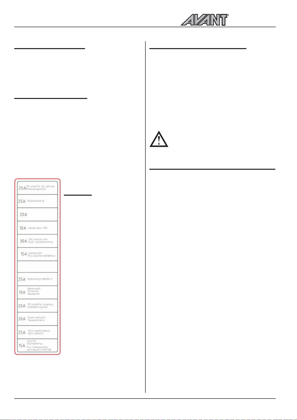
The fuse box is located on the
right side of the loader boom,
seen from drivers seat.
can be checked by first lifting the
boom so that the fuse box can
easily be reached. Remember to
use the service support.
The list on the right shows the
location and function of each fuse
in the fuse box.
If the engine does not run and
the boom cannot be lifted, the
fuses can be checked after
removing the right side cover
plate.
The red indicator no. 18 on the
dashboard indicates blown
hydraulic oil cooler fan fuse. If
the indicator is lit, check the 25A
fuse of the oil cooler fan. Contact
Avant service if necessary.
Attention! The fuse box on
machines with cab LX and DLX
is located outside the cab, on the
right side below the windscreen.
In case of contact with eyes, flush with a lot of water
for at least 15 minutes and consult a doctor immediately.
When charging the battery gives off potentially explosive
gases do not smoke when handling the battery.
In order to avoid spark emissions always disconnect
the negative (-) cable first and connect it last.
Before connecting the battery cables make sure
that the polarity is correct: faulty connection will
seriously damage the electric system of the engine.
30
Page 31
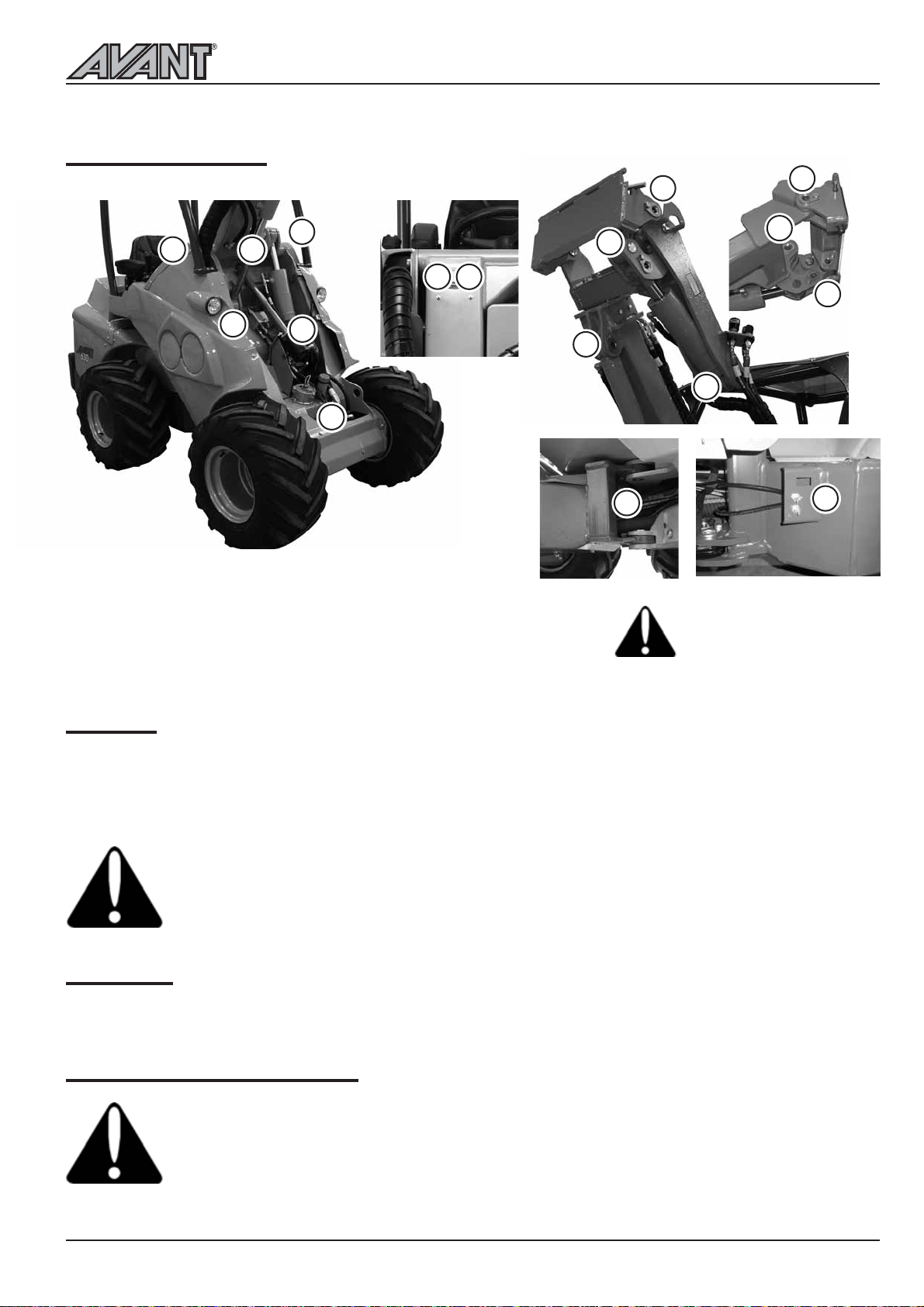
500 Series
GREASING POINTS
Service and maintenance instructions
Following pictures show the location of greasing points.
5
5
1. Lift cylinder, both ends
2. Steering cylinder, both ends
3. Tilt cylinder, both ends
4. Pivot pins on attachment
coupling plate/boom
8
9
9
1
8
2
5. Pivot pin on loader boom
6. Articulation joint
7. Tilting mechanism
8. Leveling cylinder, both ends
9. Telescopic boom, grease with
boom completely retracted
4
3
1
3
2
Check the tightness of the
pivot pin locking screws, if
loose tighten and use thread
locker.
4
7
7
6
Refueling
Check fuel level and fill the tank if necessary. Use diesel fuel only, in accordance with the instructions in the
Kubota engine Operators Manual. Use of other fuels is not allowed, because their quality and properties
cannot be guaranteed. Make sure not to let the fuel tank get empty. Should this happen, refuel and restart the engine is fitted with automatic fuel bleeding.
Do not spill fuel when refueling. should this happen, wipe the fuel away immediately in order
to avoid risk of fire.
Always stop the engine before refueling.
Keep the engine away from open fire. do not smoke during refueling.
Light bulbs
Part no. for standard front light bulb and work light bulb is 64874.
Metal structures of the loader
Contact Avant service in case the steel structure of the loader gets damaged. A faulty reparation
can cause a dangerous situation.
In case the ROPS safety frame or the FOPS canopy of the machine gets damaged, the machine
must be taken to Avant service for checking. It is not allowed to repair the ROPS and FOPS.
31
Page 32
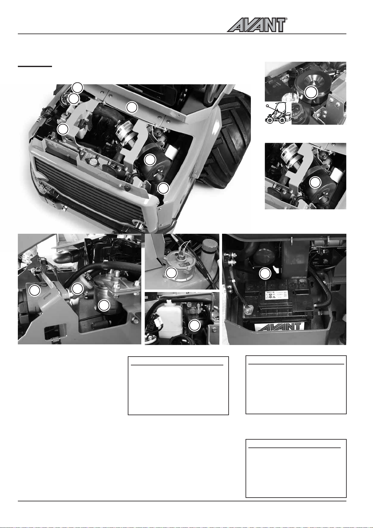
Service and maintenance instructions
FILTERS
Following pictures and tables show the location and part numbers for the filters.
500 Series
3
1
2
6
7
1
4
AVANT 520
until 5/2013
1
AVANT 520
starting from 6/2013
5
6
AVANT 520/528 filters
1. Air filter
2. Fuel filter
3. Fuel filter, pre filter
4. Engine oil filter
5. Hydraulic oil filter, return
6. Hydraulic oil filter, pressure
7. Water separator
There is also a water separator with a filter in the fuel system.
This water separator filter is not included in the filter kit and it needs
not to be changed, unless it fails.
Part no. for the water separator filter is 64963 .
Cab air filter cartridge, cab LX and DLX, part no. 65118
3
2
7
Part numbers, filters
528 Filter kit A48036 includes:
64956 Air filter
64626 Fuel filter
64657 Fuel filter, pre filter
64627 Engine oil filter
74093 Hydraulic oil filter, return
64807 Hydraulic oil filter, pressure
65229 Air filter, inner screen element,
replace only when necessary
4
Starting from 6/2013
520 Filter kit A416943 includes:
64712 Air filter
64626 Fuel filter
64657 Fuel filter, pre filter
64207 Engine oil filter
74093 Hydraulic oil filter, return
64807 Hydraulic oil filter, pressure
64713 Air filter, inner screen element,
replace only when necessary
2009 - until 5/2013
520 Filter kit A49572 includes:
65106 Air filter
64626 Fuel filter
64657 Fuel filter, pre filter
64207 Engine oil filter
74093 Hydraulic oil filter, return
64807 Hydraulic oil filter, pressure
32
Page 33

500 Series
Troubleshooting
Troubleshooting
Below is a listing of most common problems and the solutions for them. More options concerning the engine
can be found from the operators manual of the engine.
Problem
Engine does not crank
Engine cranks but does
not start, or starts and
stops immediately
Cause
Battery disconnect switch off
Battery discharged, battery
voltage too low
Blown fuse
Battery cables poorly connected
No fuel or wrong type of fuel
Engine does not get fuel, clogged
fuel filter or fuel line
Low ambient temperature
Auxiliary hydraulics control lever
is in locking position.
Battery discharged or damaged.
Remedy
Turn on the battery disconnect switch
Check and charge
Check fuses. If fuse blows again, find
out the cause. Contact service
Check battery cables and terminals,
clean and retighten if necessary
Fill the tank with correct type of fuel.
Make sure that the fuel hoses and
fuel filter are clean and have not been
frozen. Replace fuel filter, clean fuel
lines.
Hold ignition key in glow position for
longer period. If glow indicator lamp
is lit, allow it to turn off before
starting. Extend starting time up to 5
seconds.
Use correct type of engine oil
Turn the lever in center (neutral)
position. Jump start with another
battery (See page 30), then charge
the battery or replace if damaged
Engine overheats
Hydraulic system
overheats
The loader does not move
even after the parking
brake has been released.
Clogged radiator
Coolant level low
Leaking cooling system
Hydraulic oil level low
Hydraulic oil cooler thermostat
or wiring faulty
Clogged oil cooler
Fan faulty
Hydraulic oil flow restricted
Hydraulic system overloaded
Bad connection on the wiring of
the parking brake switch, blown
fuse, or faulty switch
Low hydraulic charge pressure.
Faulty solenoid valve.
Clean radiator and fan from engine
side
Add coolant
Check coolant pressure reservoir cap
for tightness. Check cooling system
and all hoses and connections.
Check and refill
Check and replace if necessary
Clean cooler and fan
Check and clean, repair if necessary
Make sure auxiliary hydraulics valve
is completely opened when using high
flow attachments. Adjust lever locking
plate if necessary.
Use attachment at lower engine rpm,
check attachment for faults.
Check wires, fuse, and switch, repair
if necessary. Contact service.
Contact service for pressure check.
Check and replace if possible. Contact
service
33
Page 34
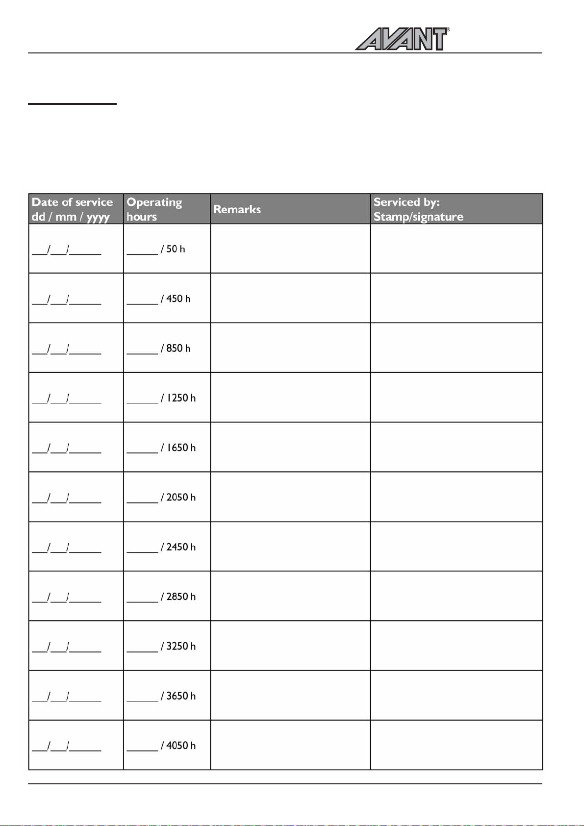
Services made
Services made
1. Customer _____________________________________________________________
2. Loader model AVANT_______________Serial no_____________________________
3. Date of delivery _______________________________________________________
500 Series
34
Page 35
500 Series
EC Declaration of conformity
EC DECLARATION OF CONFORMITY
1. Manufacturer: Avant Tecno Oy
Ylötie 1
FI-33470 YLÖJÄRVI
FINLAND
2. We hereby declare that the machines listed below conform to EC Directives,
as they are amended: 2006/42/EC (Machinery), 2004/108/EC (EMC) and
2000/14/EC (Noise Emission).
3. Category: EARTH-MOVING MACHINERY/LOADERS/COMPACT
4. Model: AVANT _____________________
5. Serial Number: _____________________
6. Year of Manufacture:
7. Directive / Conformity Assessment Procedure / Notified Body:
2006/42/EC
2004/108//EEC
2000/14/EC
Annex VI
8. Issuer of declaration and person authorized to compile technical construction file:
9. Name: Risto Käkelä
10. Position/Title: Managing Director
Self-certification ----------
Self-certification ----------
Natural Resources Institute Finland,
Type-test
Measurement and Standardization
NB 0504
Vakolantie 55, 03400 Vihti, FINLAND
11. (Signature) ___________________________
12. Place: Ylöjärvi, Finland
13. Date:
35
Page 36
Avant Tecno Oy
Ylötie 1
FIN-33470 YLÖJÄRVI, FINLAND
Tel. +358 3 347 8800
[email protected]
AVANT has a policy of continuing improvement, and retains the right to change specifications without notice. © 2016 AVANT Tecno Oy. Kaikki oikeudet pidätetään.
www.avanttecno.com
0516
 Loading...