


313S
Operators Manual
2005-

Table of contents
2
TABLE OF CONTENTS
INTRODUCTION ...............................................................................................................3
AVANT 300S SERIES WARRANTY ...................................................................................3
EC DECLARATION OF CONFORMITY ............................................................................4
HOW TO WORK SAFELY ................................................................................................. 5
DECAL LOCATIONS ..........................................................................................................6
MAIN PARTS OF THE LOADER ........................................................................................7
TECHNICAL SPECIFICATION ..........................................................................................8
TECHNICAL SPECIFICATION, ENGINES ........................................................................9
LOAD DIAGRAM ..............................................................................................................10
CONTROLS ......................................................................................................................11
STARTING THE ENGINE.................................................................................................14
STOPPING THE ENGINE ................................................................................................15
DRIVE CONTROL.............................................................................................................15
DOUBLE SPEED FUNCTION ..........................................................................................16
USING THE AUXILIARY HYDRAULICS.........................................................................16
COUPLING THE ATTACHMENTS..................................................................................17
300S SERIES SERVICE TABLE.........................................................................................18
SAFETY INSTRUCTIONS FOR MAINTENANCE ..........................................................19
MAINTENANCE INSTRUCTIONS..................................................................................20
REFUELING.......................................................................................................................21
FILTER LOCATION...........................................................................................................22
FILTER TABLE...................................................................................................................22
GREASING POINTS 300S SERIES ..................................................................................22
TROUBLESHOOTING .....................................................................................................23
ATTACHMENT LISTING .................................................................................................24
300S Series

Introduction, warranty
3
300S Series
INTRODUCTION
AVA NT TECNO OY wants to thank you for purchasing an AVANT loader. It is the result of Avants long
experience in design and manufacturing of compact loaders.
We ask you that you read and understand the contects of this manual completely before operating the loader.
This will improve your operating and maintenance efficiency, help avoid breakdowns and damage and extend
your machines life.
Contact your local AVANT dealer for any questions, service, spare parts or about any problems that may occur
with the operation of your machine.
AVANT 300S SERIES WARRANTY
This warranty specifically applies to the AVA NT 300S series loaders only and not to any attachments used
with this product.
Any repairs or modifications performed without the prior authorisation of AVA NT Tecno Oy will cancel this
warranty.
During the first year of operation or the first 750 hours (whichever is the soonest) AVA NT Tecno Oy warrants
to replace any part or repair any defect which may occur, subject to the terms detailed below:
1) The product has received regular maintenance in accordance with schedules given by the manufacturer.
2) Any damage caused by operation in a negligent manner or exceeding the approved specifications detailed
in this manual is excluded.
3) AVA NT Tecno Oy accepts no responsibility for interruption to working or any other consequential losses
resulting from any failure of the product.
4) Only AVA NT Tecno Oy approved replacement or original quality parts shall be used during routine
maintenance.
5) Any damage caused by the use of incorrect fuel, lubricants, cooling liquid or cleaning solvents is exclude
6) The Avant Warranty excludes any consumable parts (e.g. tyres, spark plugs, batteries, filters, belts etc.)
except where it can be clearly shown that these parts were defective on original supply.
7) Any damage caused resulting from the use of attachments not approved for use with this product is excluded.
8) In the event a fault occurs which is attributable to manufacturing or assembly defect you should arrange
to return your AVANT to your authorised dealer for repair. Travel and freight costs are excluded.
IDENTIFICATION OF THE LOADER
Write down the following information about your loader, it will help you when ordering parts etc.
1. Model: AVA NT_____________________Purchase date:______________________________
2. Serial number:________________________________________________________________
3. Engine serial number:__________________________________________________________
The serial number and model of the loader are printed on the manufacturers plate which is located
in the footwell (decal no. 8, see page 6). Location of engine serial number can be found in the
operating manual of the engine.

EC declaration of conformity
4
300S Series
EC DECLARATION OF CONFORMITY FOR MACHINERY
Manufacturer: AVANT TECNO OY
Address:Ylötie 1, 33470 YLÖJÄRVI, FINLAND
We hereby declare that the machines listed below conform to EC Directives: 98/37/EC
(Machinery), 89/336/EEC (EMC) and 2000/14/EC (Noise Emission).
Category: EARTH-MOVING MACHINERY/LOADERS/COMPACT
Models: AVANT 313S, 314S, 320S and 320S+
Ylöjärvi, Finland, 07.01.2003
Risto Käkelä
Managing Director

300S Series
How to work safely
5
HOW TO WORK SAFELY
An incorrect or careless operation of the loader may
be the origin of a serious accident. Before putting the
machine into operation, familiarise yourself with the
use of the machine and read and understand this
Operators Manual as well as the safety instructions.
THIS SYMBOL INDICATES
THE IMPORTANT
SAFETY FACTORS.
Understand the limitations of speed, braking, steering
and stability as well as loading capacity of the machine
before starting operation.
If you have no previous experience of the machine,
make sure to do all testing at a safe and open place
with no persons in the area of operation.
SAFETY INSTRUCTIONS
Never use the loader without instructions. Read loader
signs (decals), and this manual.
Start the operation slowly and carefully.
Do not wear loose clothing, long uncovered hair or
jewelry near machine.
When driving be comfortably seated in the driver´s
seat, keep your feet in their proper place in the footwell
and both hands on the control levers.
Operate the control levers and the lever of auxiliary
hydraulics only when sitting in the driver´s seat.
Operate the control levers with ease and without
hesitation.
When coupling the attachment, make sure that the
locking pins lock in positively.
Never put any part of the body or let anyone go under
the lifted boom.
Do not transport persons in the bucket. The machine
is not designed to lift or to transport persons.
Keep hands, feet and clothing away from any moving
part and/or hydraulic cylinder.
Never carry passengers. Keep other bystanders away
from the work area.
Drive slowly on uneven terrains. Watch out for ditches,
manholes and steep gradients.
Do not drive on too steep a gradient. Load, unload, and
turn on flat level ground.
Make sure that the ventilation is sufficient when working
indoors or otherwise confined area.
Do not use loader in an atmosphere with explosive dust
or gases or where exhaust can contact flammable
material, explosion or fire can result.
Do not transport the load with the boom lifted.
Always carry bucket or attachment as low as possible,
and put the load down whenever you leave the machine.
When lifting or lowering the load, do not operate the
boom control lever abruptly. Turn the lever smoothly
and with care.
Do not exceed rated operating capacity - follow the
load diagrams.
Do not park the machine on a surface with a gradient.
Should this be necessary, use the parking brake and
preferably turn the machine sideways and put down
the bucket. If needed, use chocks behind the wheels.
Before leaving driver´s seat:
- Lower the loader boom
- Place attachment flat on ground
- Stop the engine, remove the key
- Engage the parking brake
Never perform any maintenance or repair operation
when the engine is running.
Stop and cool the engine before adding fuel.
Never use ether or starting fluid on diesel engines with
glow plugs. Use only starting aids as approved by engine
manufacturer.
Keep the engine area clean of flammable materials.
Wear eye protection when servicing, and hard hat or
other protective equipment as needed.
When connecting a booster battery for "jump" start,
always make last connection (negative cable) to engine,
never at battery. When removing the "jump" start cable,
always remove the negative cable (-) from engine first.
Never charge a frozen battery.
Lead acid batteries produce flammable and explosive
gases. Keep arcs, sparks, flames and lighted tobacco
away from battery.
Battery acid causes severe burns. In case of acid contact,
wash immediately with water for several minutes and
get medical attention in case of eye contact.
Use a piece of cardboard to check for hydraulic leaks.
Leaking fluids under pressure can enter the skin and
cause serious injury. Medical attention is required if
hydraulic or other fluids contact skin.
Never modify the loader or add attachments not
approved by AVA NT Tecno Oy.
Do not smoke during refueling or driving.
Read this Operator's Manual carefully, especially if you
are unfamiliar with the safe use and operation of the
machine.
Decal locations
6
300S Series
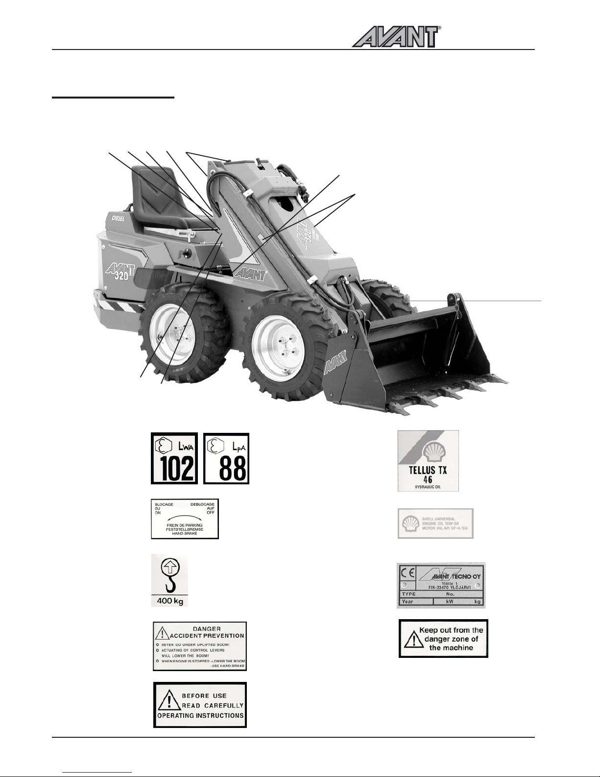
DECAL LOCATIONS
The following decals and signs should always be installed on the loader. If any of these decals has been
removed or is unreadable it should be replaced without delay.
l
j
k
m
no
r
l
j
k
m
n
o
p
q
r
p
q
300S Series
Main parts of the loader
7
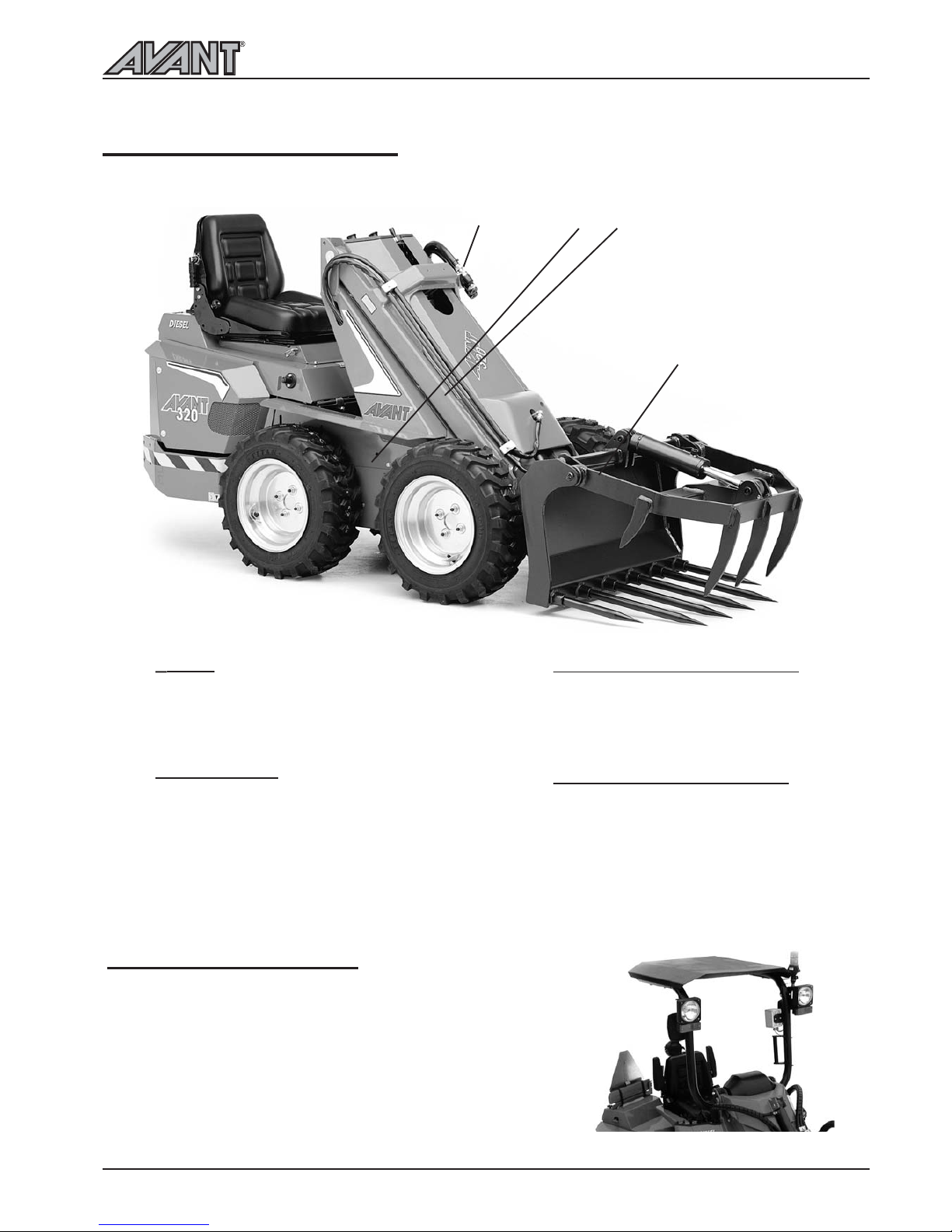
MAIN PARTS OF THE LOADER
Following picture shows the main parts of the loader:
j
k
m
l
j
k
m
Frame
The machine has a rigid frame, on which
all the hydraulic components, engine,
control valves, loader boom, wheels etc.
are mounted.
Loader boom
Loader boom is mounted on the front
frame with two pivot pins. The attachment
coupling plate is mounted on the lower
end of the boom. There are two types of
booms: standard boom with fixed length
and the optional telescopic boom which
extends 500 mm hydraulically.
Attachment coupling plate
Attachments are mounted on the
attachment coupling plate.
Auxilary hydraulics outlet
The hydraulic hoses of hydraulically
operated attachments are mounted on
this outlet with quick couplers. The outlet
is double acting: it has two pressure lines
and one return line. It is also possible to
install an auxiliary hydraulics outlet in the
rear of the machine (optional extra).
l
ROPS AND FOPS (Option)
1. ROPS frame
ROPS frame complies with the ISO 3471 / SAE J1040 standard.
Total machine height with ROPS frame is 1990 mm.
1. FOPS canopy, mounts on the ROPS
FOPS safety canopy exceeds the ISO 3449 Level 1 / SAE J1043
FOPS criteria. Total machine height with FOPS is 2050 mm.

Technical specification
8
300S Series
TECHNICAL SPECIFICATION
Model AVANT 313S AVANT 314S AVANT 320S
AVANT
320S+
Length 1680 mm 1950 mm 1950 mm 1950 mm
Width 790-1050 mm
(depending on
tyre size)
790-1050 mm
(depending on
tyre size)
790-1050 mm
(depending on
tyre size)
790-1050 mm
(depending on
tyre size)
Standard tyre size
Width
5x10 TR
940 mm
23*8.50-12
1020 mm
23*8.50-12
1020 mm
23*8.50-12
1020 mm
Height 1200 mm 1250 mm 1250 mm 1250 mm
Axle width 795 mm 795 mm 795 mm 795 mm
Ground clearance
206 mm 206 mm 206 mm 206 mm
Weight 530 kg 610 kg 720 kg 720 kg
Single speed model
Drive speed:
Double speed model
0 5 km/h
0 9 km/h 0 9 km/h 0 9 km/h 0 9 km/h
0 5 km/h
Drive hydraulics hydraulic four wheel drive hydraulic four wheel drive
Auxiliary hyraulics
flow and pressure
28 l/min single pump, 22,5 + 22,5 l/min
double pump, 175 bar
22,5+22,5 l/min
200 bar
22,5+22,5 l/min
220 bar
Turning radius
same as the length
of the machine
same as the length
of the machine
same as the length
of the machine
same as the length
of the machine
Lifting height with
standard boom
2100 mm 2100 mm 2100 mm 2100 mm
Lifting height with
telescopic boom
(Option)
2400 mm 2400 mm 2400 mm 2400 mm
Max. pulling force 6500 N 6500 N 7700 N 10 000 N
Max. lifting capacity
(hydr.)
750 daN 750 daN 850 daN 880 daN
Tipping load*) 600 kg 650 kg
700 kg
700 kg
Engine Honda GX 390
petrol
Kubota Z 482
diesel
Kubota D 722
diesel
Kubota D 722
diesel
Engine output 10 kW (13 hp) 10,5 kw (14 hp) 14 kW (20 hp) 14 kW (20 hp)
*) with standard lift arm, 80 kg driver and 30 kg extra back weight, on flat even surface
 Loading...