

Autonics TK Series Catalog Page
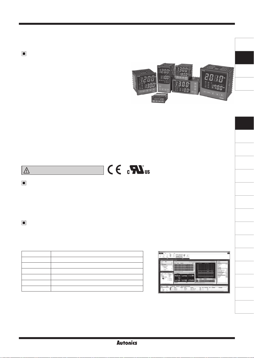
TK Series
High Performance, General-Purpose, PID Control
Temperature Controller
Features
● 50ms high-speed sampling rate and ±0.3% display accuracy
● Simultaneous heating and cooling control function
● Automatic/manual control option
● Switch between current output and SSR drive output
● SSR drive output (SSRP function) control options:
ON/OFF control, cycle control, phase control
● Communication output models available:
RS485 (Modbus RTU)
● Parameter conguration via PC
(RS485 communication)
- DAQMaster software included (comprehensive device management software)
- Communication converter sold separately
: SCM-WF48 (Wi-Fi to RS485·USB wireless communication converter),
SCM-US48I (USB to RS485 converter), SCM-38I (RS232C to RS485 converter),
SCM-US (USB to serial converter)
● User-friendly parameter features (via DAQMaster)
● SV preset function (up to 4 set values) using digital input terminals
● Heater disconnect alarm function (CT input)
- Current transformer (CT) sold separately: CSTC-E80LN, CSTC-E200LN, CSTS-E80PP
● Various input types and temperature ranges
Please read “Safety Considerations”
in the instruction manual before using.
Manual
● For the detail information and instructions, please refer to the user manual and user manual for communication, and be
sure to follow cautions written in the technical descriptions (catalog, website).
Visit our website (www.autonics.com) to download manuals.
● User manual describes for specications and function, and communication manual describes for RS485 communication
(Modbus RTU protocol) and parameter address map data.
Comprehensive Device Management Program (DAQMaster)
● DAQMaster is comprehensive device management program. It is available for parameter setting, monitoring, and user
parameter group setting, parameter mask setting for only TK4 Series.
● Visit our website (www.autonics.com) to download user manual and comprehensive device management program.
< DAQMaster screen >< Computer specication for using software >
Item Minimum requirements
System IBM PC compatible computer with Intel Pentium Ⅲ or above
Operating system Microsoft Windows 98/NT/XP/Vista/7/8/10
Memory 256MB or more
Hard disk More than 1GB of free hard disk space
VGA 1024×768 or higher resolution display
Others RS-232 serial port (9-pin), USB port
SENSORS
CONTROLLERS
MOTION DEVICES
SOFTWARE
(J)
Temperature
Controllers
(K)
SSRs
(L)
Power
Controllers
(M)
Counters
(N)
Timers
(O)
Digital
Panel Meters
(P)
Indicators
(Q)
Converters
(R)
Digital
Display Units
(S)
Sensor
Controllers
(T)
Switching
Mode Power
Supplies
(U)
Recorders
(V)
HMIs
(W)
Panel PC
J-61
(X)
Field Network
Devices
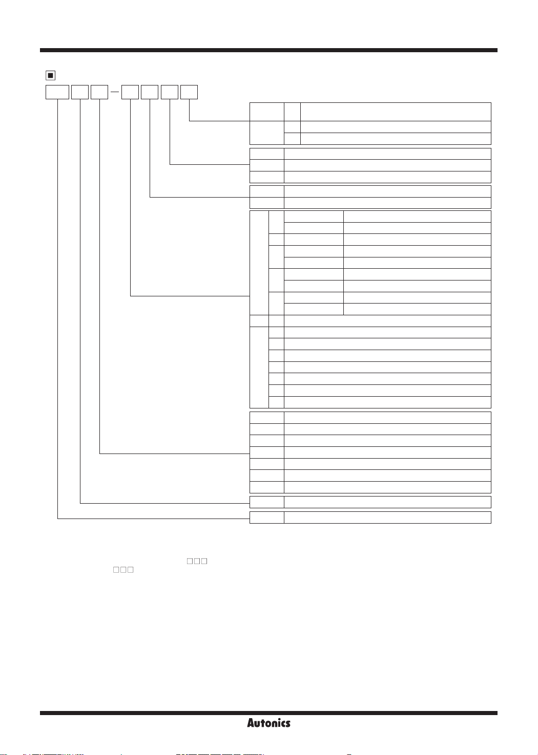
TK Series
Ordering Information
TK 4 S 1 4 R R
Power supply
Option input/output
Size
Digit
Item
OUT 2
control output
OUT 1 control output
※
2
※
Standard N
9
Heating &
Cooling
R Relay output
※
7
※
8
S
None
※
Select in case of standard control (Heating or Cooling)
R Relay output
※
10
C Current output or SSR drive output selectable
SSR drive output (standard ON/OFF control, phase control, cycle control)
C Current output or SSR drive output selectable
※
6
2
24VAC 50/60Hz, 24-48VDC
4 100-240VAC 50/60Hz
Standard Alarm output 1+CT input
1
Heating&Cooling Alarm output 2
2 Standard Alarm output 1+Alarm output 2
Standard Alarm output 1+Digital input (DI-1, DI-2)
D
N
Heating&Cooling Digital input (DI-1, DI-2)
Standard Alarm output 1+Transmission output
R
Heating&Cooling Transmission output
Standard Alarm output 1+RS485 communication output
T
Heating&Cooling RS485 communication output
SP 1 Alarm output 1
1 Alarm output 1
2 Alarm output 1+Alarm output 2
S
R Alarm output 1+Transmission output
M
W
T Alarm output 1+RS485 communication output
H
A Alarm output 1+Alarm output 2+Transmission output
L
B Alarm output 1+Alarm output 2+RS485 communication output
D Alarm output 1+Alarm output 2+Digital input (DI-1, DI-2)
N DIN W48×H24mm
SP DIN W48×H48mm (11-pin plug type)
S DIN W48×H48mm (Terminal block type)
M DIN W72×H72mm
W DIN W96×H48mm
H DIN W48×H96mm
L DIN W96×H96mm
4 9999 (4-digit)
TK Temperature/Process Controller
※
3
※
4
※
5
※
1
1. 11Pin socket(PG-11, PS-11(N)): Sold separately
※
2. In case of TK4N/TK4SP Series, option control output selection and digital input will be limited due to number of terminals.
※
3. The CT input model of TK4N is selectable only for standard model which has alarm 1.
※
4. The Heaing & Cooling model of TK4N-1 has only alarm output 2.
※
5. Only for TK4S-D , OUT2 output terminal is used as DI-2 input terminal.
※
6. Does not support in TK4N.
※
7. “S” represents SSR drive output support models which SSRP function (standard ON/OFF, cycle, phase)control are available. “C”
※
represents selectable current and SSR drive output support models.
8. Does not support in AC/DC voltage type model.
※
9. Select “R” or “C” type in case of using heating & cooling control. “N” type in case of using standard control.
※
10. In case of Relay OUT2 model, alarm output 3 is available only when control output operation mode [
※
cooling [
or cooling[
COOL
]. In case of current output, trans. output 2 is available only when control output operation mode [
COOL
].
O-FT
] is set heating [
O-FT
] is set heating [
J-62
HEAT
] or
HEAT
]
High Performance, General-Purpose, PID Control
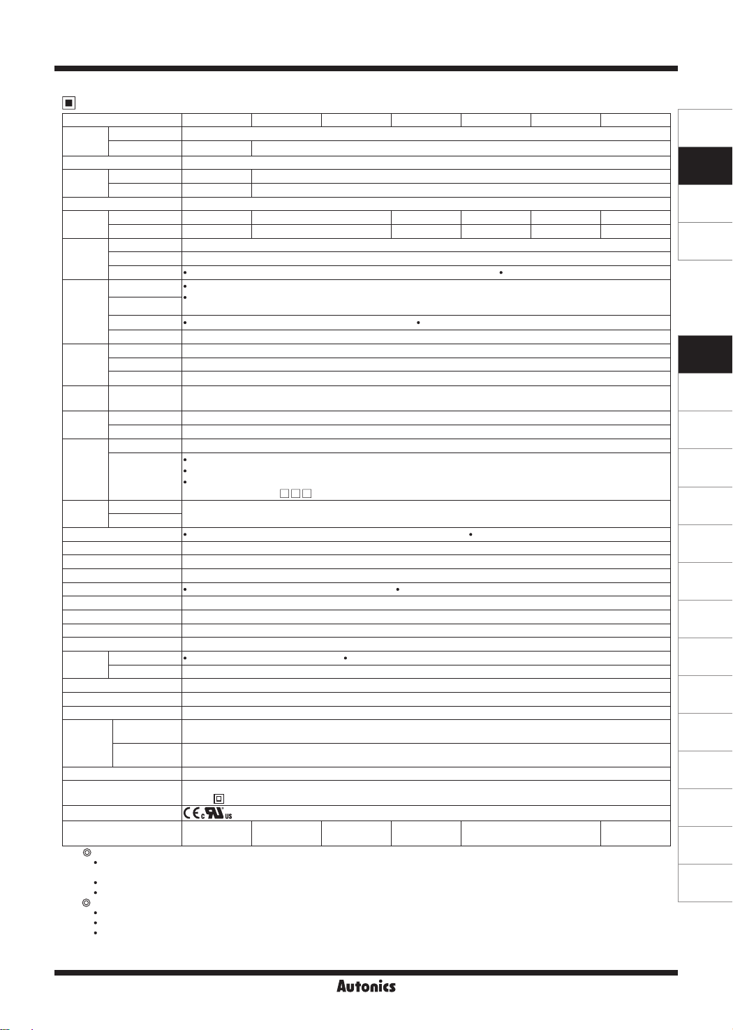
Specifications
Series
Power
supply
AC voltage 100-240VACᜠ 50/60Hz
AC/DC voltage
Allowable voltage range 90 to 110% of rated voltage
Power
consumption
AC voltage Max. 6VA Max. 8VA
AC/DC voltage
Display method 7-segment (PV: red, SV: green), other display part (green, yellow, red) LED method
Character
size
Input
type
PV (W×H) 4.5×7.2
SV (W×H) 3.5×5.8
RTD JPt100Ω, DPt100Ω, DPt50Ω, Cu100Ω, Cu50Ω, Nikel 120Ω (6 types)
Thermocouple K(CA), J(IC), E(CR), T(CC), B(PR), R(PR), S(PR), N(NN), C(TT), G(TT), L(IC), U(CC), Platinel Ⅱ (13 types)
Analog Voltage: 0-100mVDCᜡ, 0-5VDCᜡ, 1-5VDCᜡ, 0-10VDCᜡ (4 types) Current: 0-20mA, 4-20mA (2 types)
RTD
Display
accuracy
Thermocouple
Analog At room temperature (23℃±5℃): ±0.3% F.S. ±1-digit Out of range of room temperature: ±0.5% F.S. ±1-digit
CT input ±5% F.S. ±1-digit
Control
output
Alarm
output
Option
output
Relay OUT1, OUT2: 250VACᜠ 3A, 30VDCᜡ 3A, 1a
SSR 11VDCᜡ±2V 20mA Max.
Current DC4-20mA or DC0-20mA selectable (load 500Ω max.)
Relay
Transmission DC4-20mA (load 500Ω max., accuracy: ±0.3% F.S.)
Communication RS485 communication output (Modbus RTU)
CT input 0.0-50.0A (primary heater current value measuring range) ※CT ratio = 1/1000 (except TK4SP)
Option
input
Control
type
Digital input
Heating, cooling
Heating&cooling
Hysteresis RTD/Thermocouples: 1 to 100
Proportional band (P) 0.1 to 999.9
Integral time (I) 0 to 9999 sec
Derivative time (D) 0 to 9999 sec
Control period (T) Relay output, SSR drive output: 0.1 to 120.0 sec Current output or SSR drive output selectable: 1.0 to 120.0 sec
Manual reset value 0.0 to 100.0%
Sampling period 50ms
Dielectric strength 2,000VAC 50/60Hz for 1 min (between power source terminal and input terminal)
Vibration 0.75mm amplitude at frequency of 5 to 55Hz (for 1 min) in each X, Y, Z direction for 2 hours
Relay
life cycle
Mechanical OUT1/2: min. 5,000,000 times AL1/2: min. 20,000,000 times (TK4H/W/L: min. 5,000,000 times)
Electrical OUT1/OUT2, AL1/AL2: min. 100,000 operations
Insulation resistance Over 100MΩ (at 500VDC megger)
Noise immunity ±2kV R-phase, S-phase the square wave noise (pulse width: 1㎲) by the noise simulator
Memory retention Approx. 10 years (when using non-volatile semiconductor memory type)
Ambient
Environment
temperature
Ambient
humidity
Protection structure IP65 (front panel) ※TK4SP: IP50 (front panel)
Insulation type
Approval
※
2
Weight
※
1: At room temperature (23℃±5℃)
Thermocouple K, J, T, N, E type, below -100℃/Thermocouple L, U, PL
: (PV ±0.3% or ±2℃, select the higher one) ±1-digit
Thermocouple C, G, R, S type, below 200℃: (PV ±0.3% or ±3℃, select the higher one) ±1-digit
Thermocouple B type, below 400℃: there is no accuracy standards.
Out of room temperature range
RTD Cu50Ω, DPt50Ω: (PV ±0.5% or ±3℃, select the higher one) ±1-digit
Thermocouple R, S, B, C, G type: (PV ±0.5% or ±5℃, select the higher one) ±1-digit
Others, Below -100℃: within ±5
In case of TK4SP Series, ±1℃ will be added to the degree standard.
※
The weight includes packaging. The weight in parenthesis is for unit only.
2:
※
Environment resistance is rated at no freezing or condensation.
TK4N TK4SP TK4S TK4M TK4W TK4H TK4L
-
-
At room temperature (23℃±5℃): (PV ±0.3% or ±1℃, select the higher one) ±1-digit
Out of room temperature range: (PV ±0.5% or ±2℃, select the higher one) ±1-digit
※
In case of TK4SP Series, ±1℃ will be added.
AL1, AL2: 250VACᜠ 3A 1a
※
TK4N AL2: 250VACᜠ 0.5A 1a (max.125VA), TK4SP has only AL1.
24VACᜠ 50/60Hz, 24-48VDC
ᜡ
Max. 8VA (24VAC 50/60Hz), max. 5W (24-48VDC)
7.0×14.0
mm
mm
5.0×10.0
mm
mm
9.5×20.0
7.5×15.0
mm
mm
8.5×17.0
6.0×12.0
mm
mm
7.0×14.6
6.0×12.0
※
1
mm
mm
11.0×22.0
7.0×14.0
Contact Input: ON - max. 2kΩ, OFF - min. 90kΩ
Non-contact Input: ON - residual votage max. 1.0VDCᜡ, OFF - leakage current max. 0.1mA
Outflow current: approx. 0.5mA
※
TK4S/M: 1 (TK4S-D : 2, TK4SP: none), TK4N/H/W/L: 2
ON/OFF, P, PI, PD, PID control
(0.1 to 999.9%)
℃/℉
-10 to 50℃, storage: -20 to 60
℃/℉
℃
(0.1 to 100.0
) variable Analog: 1 to 100-digit
℃/℉
35 to 85%RH, storage: 35 to 85%RH
Double insulation or reinforced insulation
(mark: , dielectric strength between the measuring input part and the power part: 2kV)
Approx. 140g
(approx. 70g)
Approx. 130g
(approx. 85g)
Approx. 150g
(approx. 105g)
Approx. 210g
(approx. 140g)
, RTD Cu50Ω, DPt50Ω
Ⅱ type
Approx. 211g
(approx. 141g)
Approx. 294g
(approx. 198g)
℃
mm
mm
J-63
SENSORS
CONTROLLERS
MOTION DEVICES
SOFTWARE
(J)
Temperature
Controllers
(K)
SSRs
(L)
Power
Controllers
(M)
Counters
(N)
Timers
(O)
Digital
Panel Meters
(P)
Indicators
(Q)
Converters
(R)
Digital
Display Units
(S)
Sensor
Controllers
(T)
Switching
Mode Power
Supplies
(U)
Recorders
(V)
HMIs
(W)
Panel PC
(X)
Field Network
Devices
TK Series
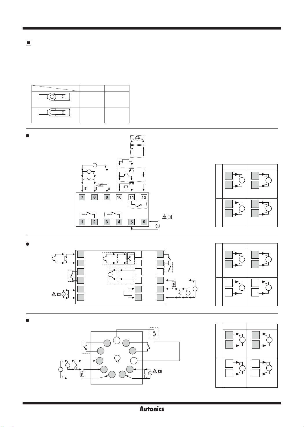
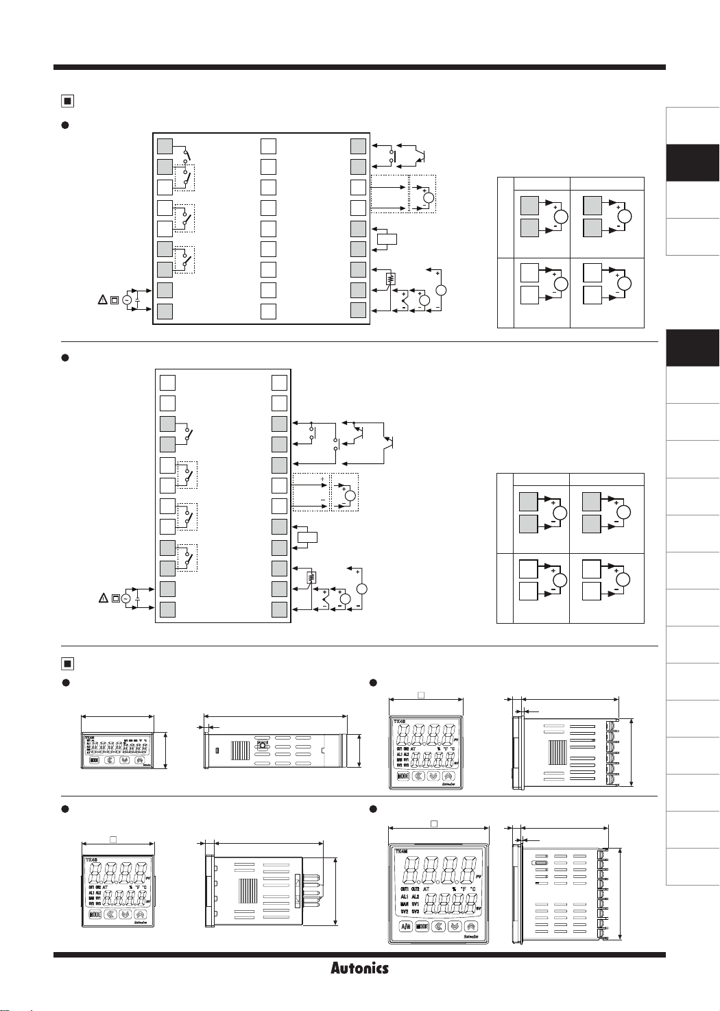
Connections
※
Please check the polarity when connecting temperature sensor or analog input.
※
Standard model has shaded terminals only.
※
Operation mode of heating&cooling OUT 2 relay output model is heating or cooling, OUT 2 is available as alarm output 3.
(except TK4N Series).
※
Operation mode of heating&cooling OUT 2 current output model is heating or cooling, OUT 2 is available as transmission
output 2.
※
Use teminals of size specied below.
a b
a
b
<Round>
<Forked>
Min.
3.0mm
a
b
Min.
3.0mm
Max.
5.8mm
Max.
5.8mm
TK4N
TK4S
Digital Input
Non-contact,
contact input
OUT1: Relay
250VAC 3A 1a
30VDC 3A 1a
RESISTIVE LOAD
SOURCE
100-240VAC 50/60Hz 8VA
24VAC 50/60Hz 8VA
24-48VDC 5W
mA
V
TC
SENSOR
RTD
OUT2/AL1 OUT:
250VAC 3A 1a
30VDC 3A 1a
RESISTIVE LOAD
DI-1 DI-2
1
DI-1 DI-2
2
3
4
5
-
+
6
Digital Input
Non-contact,
contact input
Transfer
Output
DC4-20mA
OUT1:
250VAC 3A 1a
30VDC 3A 1a
RESISTIVE LOAD
Current
Transformer
0.0-50.0A
Transfer Output
DC4-20mA
Communication
Output
RS485 (A+)
RS485 (B-)
Current Transformer
CT
DI-1
DI-1
0.0-50.0A
DI-2
Digital Input
Non-contact, contact input
DI-2
AL2 OUT:
250VAC 0.5A 1a
RESISTIVE LOAD
SSR Current
3 3
V
4 4
OUT1OUT2
11VDC±2V
20mA Max.
1 1
DC0/4-20mA
Load 500Ω Max.
V
mA
mA
2 2
SOURCE
100-240VAC
50/60Hz 6VA
OUT2: Relay
250VAC 3A 1a
30VDC 3A 1a
RESISTIVE LOAD
Communication
Output
7
8
9
10
11
12
AL1 OUT:
250VAC 3A 1a
RESISTIVE LOAD
AL2 OUT:
250VAC 3A 1a
RESISTIVE LOAD
A
B
B'
RTD TC
SENSOR
mA
V
13
14
15
RS485 (A+)
mA
16
RS485 (B-)
17
CT
18
11VDC±2V
20mA Max.
SSR Current
3 3
4 4
OUT1OUT2
11VDC±2V
20mA Max.
13 13
14 14
11VDC±2V
20mA Max.
DC0/4-20mA
Load 500Ω Max.
V
DC0/4-20mA
Load 500Ω Max.
V
DC0/4-20mA
Load 500Ω Max.
mA
mA
TK4SP
J-64
OUT1: Relay
250VAC 3A 1a
30VDC 3A 1a
RESISTIVE LOAD
V
mA
TC
SENSOR
B'
B
A
RTD
OUT2: Relay
250VAC 3A 1a
30VDC 3A 1a
6
5
4
3
2
7
8
9
10
11
1
RESISTIVE LOAD
AL1:
Relay
250VAC 3A 1a
RESISTIVE LOAD
-
+
SOURCE
100-240VAC 50/60Hz 8VA
24VAC 50/60Hz 8VA
24-48VDC 5W
SSR Current
5 5
V
4 4
OUT1OUT2
11VDC±2V
20mA Max.
9 9
DC0/4-20mA
Load 500ΩMax.
V
6 6
11VDC±2V
20mA Max.
DC0/4-20mA
Load 500ΩMax.
mA
mA
High Performance, General-Purpose, PID Control
Connections
TK4M
-
SOURCE
100-240VAC 50/60Hz 8VA
24VAC 50/60Hz 8VA
24-48VDC 5W
+
TK4H/TK4W/TK4L
-
SOURCE
100-240VAC 50/60Hz 8VA
24VAC 50/60Hz 8VA
24-48VDC 5W
Dimensions
+
TK4N Series
48
1
2
3
4
5
6
7
8
9
1
2
3
4
5
6
7
8
9
10
11
12
AL1 OUT:
250VAC 3A 1a
RESISTIVE LOAD
AL2 OUT:
250VAC 3A 1a
RESISTIVE LOAD
OUT2: Relay
250VAC 3A 1a
30VDC 3A 1a
RESISTIVE LOAD
OUT1: Relay
250VAC 3A 1a
30VDC 3A 1a
RESISTIVE LOAD
AL1 OUT:
250VAC 3A 1a
RESISTIVE LOAD
AL2 OUT:
250VAC 3A 1a
RESISTIVE LOAD
OUT2: Relay
250VAC 3A 1a
30VDC 3A 1a
RESISTIVE LOAD
OUT1: Relay
250VAC 3A 1a
30VDC 3A 1a
RESISTIVE LOAD
3
19
20
21
22
23
24
25
26
27
13
14
15
16
17
18
19
20
21
22
23
24
94.8
Communication Output
Digital Input
Non-contact, contact input
RS485 (A )
RS485 (B )
CT
A
B
B'
RTD TC
SENSOR
DI-2
Current
Transformer
0.0-50.0A
10
11
RS485 (A+)
12
RS485 (B-)
13
Communication Output
14
15
16
17
18
DI-1DI-1
Transfer Out
mA
DC4-20mA
mA
V
DI-1
CT
A
B
B
'
RTD TC
SENSOR
TK4S Series
Digital Input
DI-1
Non-contact, contact input
mA
Current
Transformer
0.0-50.0A
V
DI-2
48
mA
Transfer Output
DC4-20mA
SSR Current
6
OUT1OUT2
7 7
11VDC±2V
20mA Max.
4 4
5
11VDC±2V
20mA Max.
※
Digital input is not electrically
6
V
DC0/4-20mA
Load 500Ω Max.
V
5
DC0/4-20mA
Load 500Ω Max.
insulated from internal circuits,
so it should be insulated
when connecting other
circuits. (Photocoupler, Relay,
Independent switch)
SSR Current
9
OUT1OUT2
10
11VDC±2V
20mA Max.
9
V
10
DC0/4-20mA
Load 500Ω Max.
7 7
V
8 8
11VDC±2V
20mA Max.
6
DC0/4-20mA
Load 500Ω Max.
64.5
1.7
mA
mA
mA
mA
(unit: mm)
SENSORS
CONTROLLERS
MOTION DEVICES
SOFTWARE
(J)
Temperature
Controllers
(K)
SSRs
(L)
Power
Controllers
(M)
Counters
(N)
Timers
(O)
Digital
Panel Meters
(P)
Indicators
(Q)
Converters
(R)
Digital
Display Units
(S)
Sensor
Controllers
(T)
Switching
Mode Power
Supplies
TK4SP Series
48
24
21.8
(U)
45
Recorders
(V)
HMIs
TK4M Series
1.7
64.5
67.5
J-65
(W)
Panel PC
(X)
Field Network
Devices
72
6
72.2
6
44.8
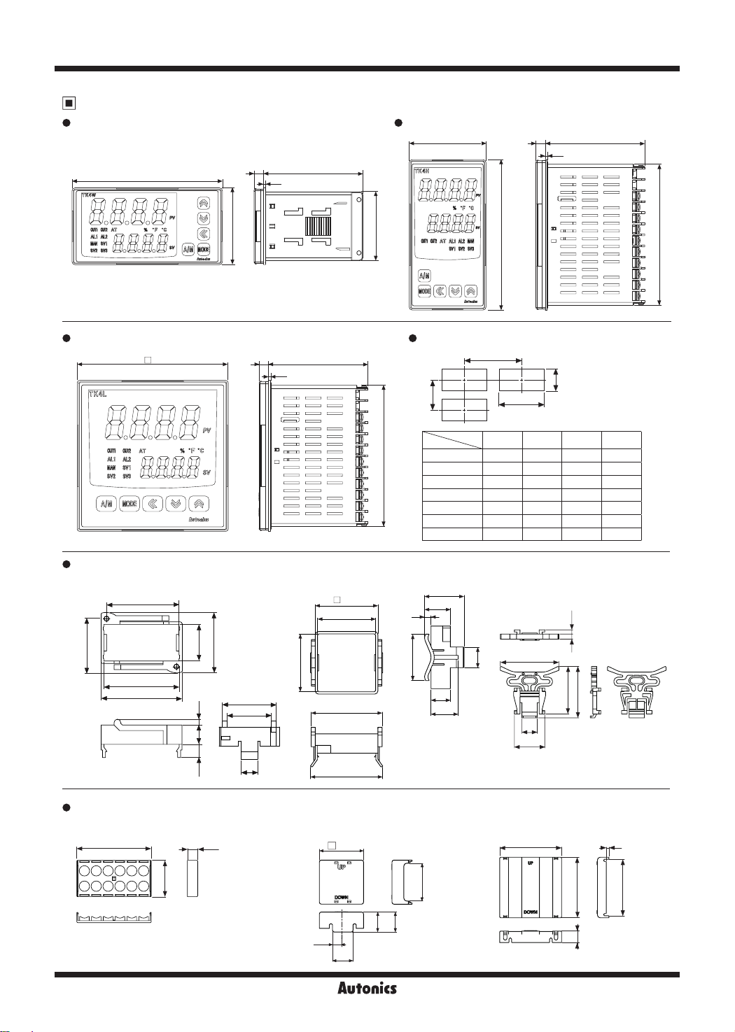
TK Series
Dimensions
TK4W Series
96
(unit: mm)
TK4H Series
48
6
64.5
1.5
6
64.5
1.5
TK4L Series
Bracket
TK4N Series
●
48
44.7
96
91.5
Panel cut-out
96
6
64.5
1.5
B
Model
91.5
TK4N Min. 55 Min. 37 45
TK4S Min. 65 Min. 65 45
TK4SP Min. 65 Min. 65 45
TK4M Min. 90 Min. 90
TK4H Min. 65
TK4W
TK4L
TK4S, TK4SP Series
●
42
48.6
45
31
20
5
A
D
C
Size
A B C D
Min. 115
Min. 115
Min. 65 92
Min. 115 Min. 115
TK4M/W/H/L Series
●
68
45
92
3.34
+ 0.6
0
+ 0.6
0
+ 0.6
0
+ 0.7
0
+ 0.6
0
+ 0.8
0
+ 0.8
0
(unit: mm)
+ 0.3
22.2
0
+ 0.6
45
0
+ 0.6
45
0
+ 0.7
68
0
+ 0.8
92
0
+ 0.6
45
0
+ 0.8
92
0
22
28.8
36.3
45.2
48.6
3.5
11.6
7.9
Terminal cover (sold separately)
TK4N Cover (48×24mm)
●
6.244.6 70
21.8
TK4N COVER is accessory.
※
J-66
32.4
26.4
10
44.9
55
56
RSA Cover (48×48mm)
●
48.4
18
9.8
22.5
36
16
15
21
46
37.5
40.5
12
23.9
RMA Cover (72×72mm)
●
3
41.5
68.5
64
22
13
High Performance, General-Purpose, PID Control
Dimensions
Terminal cover (sold separately)
RHA Cover (48×96mm, 96×48mm)
●
47.2
4
RLA Cover (96×96mm)
●
94
3
(unit: mm)
SENSORS
CONTROLLERS
91.5
86
13
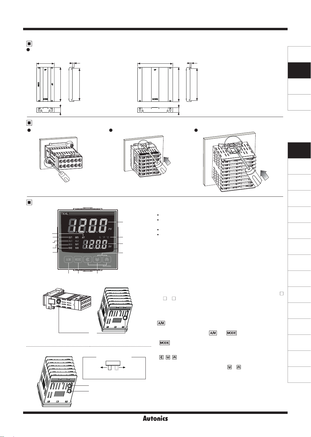
Product Mounting
91.5
13
86
TK4N (48×24mm) Series TK4S/SP (48×48mm) Series Other Series
(+) driver
※
※
Insert the unit into a panel, fasten
the bolt with a (+) driver.
Unit Description
Insert the unit into a panel, fasten
the bracket by pushing with tools
with a (-) driver.
1
6
8
7
4
5
10
9
11
TK4N Series
※
The input selection switch (TC, RTD/mV, V, mA) switch disappears.
Select input type [
IN-T
13
] in parameter 3 group.
3
2
12
Other Series
The previous model
Input selection switch
TC, RTD
(Front
direction)
mV, V, mA
(Back
direction)
14
13
(-)driver
1. Measured value (PV) display part:
RUN mode: It displays currently measured value (PV).
Setting mode: It displays the parameter.
2. Set value (SV) display part:
RUN mode: It displays the set value (SV).
Setting mode: It displays the set value of the parameter.
3. Unit (℃/℉/%) indicator:
[
] in parameter 3 group. (In case of TK4N, % is not supported)
UNT
4. Manual control indicator:
5. Multi SV indicator:
It displays the unit set at display unit
It turns ON during manual controlling.
One of SV1 to 3 indicators will be ON in
case of selecting multi SV function.
6. Auto tuning indicator:
It flashes by 1 sec when executing auto
tuning.
7. Alarm output (AL 1, AL 2) indicator:
alarm output is ON.
8. Control output (OUT 1, OUT 2) indicator:
control output is ON.
※
During cycle/phase controlling in SSRP function model (TK4
- 4S ) when MV is over 5.0%, it turns ON.
※
To use current output, when MV is 0.0% in manual control, it
turns OFF. Otherwise, it always turns ON. When MV is over
3.0% in auto control, it turns ON and when MV is below 2.0%,
it turns OFF.
9. key:
control.
※
It is used when switching auto control to manual
TK4N/S/SP do not have
key.
simultaneously.
10. key:
It is used when entering parameter setting group,
returning to RUN mode, moving parameter, saving the set
value.
11. , , key:
It is used when entering the set value changing
mode and moving or changing up/down digit.
12. Digital input key:
When pressing + keys for 3 sec at the
same time, it operates the function (RUN/STOP, alarm clear,
auto tuning) set at digital input key [
13. PC loader port:
It is the PC loader port for serial communication
to set parameter and monitoring by DAQMaster installed in PC.
Use this for connecting SCM-US (USB to Serial converter, sold
separately).
14. Input selection switch:
Used when switching sensor (TC, RTD)
input ↔ analog input (mV, V, mA). (only the previous model)
It turns ON when the
It turns ON when the
key operates switching
] in parameter 5 group.
DI-K
(-) driver
MOTION DEVICES
SOFTWARE
(J)
Temperature
Controllers
(K)
SSRs
(L)
Power
Controllers
(M)
Counters
(N)
Timers
(O)
Digital
Panel Meters
(P)
Indicators
(Q)
Converters
(R)
Digital
Display Units
(S)
Sensor
Controllers
(T)
Switching
Mode Power
Supplies
(U)
Recorders
(V)
HMIs
(W)
Panel PC
(X)
Field Network
Devices
J-67

TK Series
Sold Separately
Communication converter
SCM-WF48
( Wi-Fi to RS485·USB wireless
communication converter)
Current transformer (CT)
CSTC-E80LN
10.5
CSTC-E200LN
13.5
CSTS-E80PP
Ø6
21.4
15.4
0.5
Ø23.3
Ø7
7
Ø37.1
Ø13
10
725.4
SCM-US48I
(USB to RS485 converter)
K (black)
L (white)
15026.5
K (black)
L (white)
15040.8
2.9
3
(unit: mm)
3
(unit: mm)
3.8
OUTPUT IN VOLTS RMS (V)
0.001
4.5
OUTPUT IN VOLTS RMS (V)
0.001
SCM-38I
(RS232C to RS485 converter)
10
Ta=25
℃
1
0.1
0.01
0.1
1 10 100 1000
SENSED CURRENT IN AMPS RMS (Io)
10
Ta=25
℃
1
0.1
0.01
0.1 1 10 100 1000
SENSED CURRENT IN AMPS RMS (Io)
10
Ta=25
℃
1
F=50Hz
100Ω
10Ω
F=50Hz
100Ω
10Ω
F=50Hz
100Ω
10Ω
SCM-US
(USB to Serial converter)
Max. load current: 80A (50/60Hz)
※Max. load current for TK4 Series
is 50A.
Current ratio: 1/1000
Wire wounded resistance: 31Ω±10%
Max. load current: 200A (50/60Hz)
※Max. load current for TK4 Series
is 50A.
Current ratio: 1/1000
Wire wounded resistance: 20Ω±10%
0.1
10.5
40.2
Ø3.4
※
Do not supply primary current in case that CT output is open. High voltage will be generated in CT output.
※
The current for above CTs is 50A same but inner hole sizes are different. Please use this for your environment.
31
2.7
0.01
OUTPUT IN VOLTS RMS (V)
0.001
0.1 1 10 100 1000
10
(unit: mm)
SENSED CURRENT IN AMPS RMS (Io)
J-68
Max. load current: 80A (50/60Hz)
※
Max. load current for TK4 Series
is 50A.
Current ratio: 1/1000
Wire wounded resistance 31Ω±10%
 Loading...