

DR W161011AC
Autonics
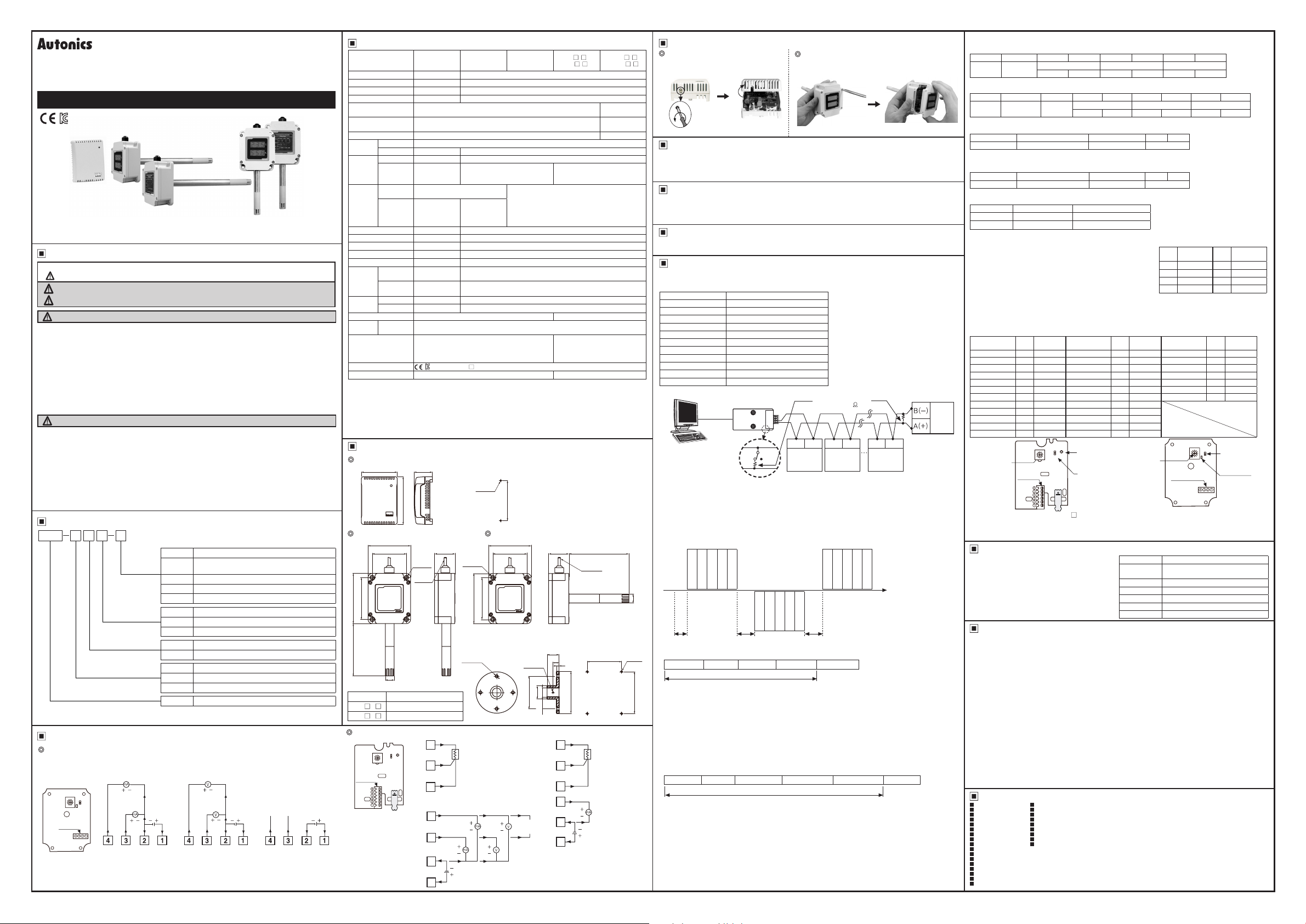
Temperature/Humidity Transducer
THD SERIES
I N S T R U C T I O N M A N U A L
Please read the following safety considerations before use.
Safety Considerations
Please observe all safety considerations for safe and proper product operation to avoid hazards.
※
symbol represents caution due to special circumstances in which hazards may occur.
※
Warning
Caution
Warning
1. Fail-safe device must be installed when using the unit with machinery that may cause
serious injury or substantial economic loss. (e.g. nuclear power control, medical equipment,
ships, vehicles, railways, aircraft, combustion apparatus, safety equipment, crime/disaster
prevention devices, etc.)
Failure to follow this instruction may result in re, personal injury, or economic loss.
2. Do not connect, repair, or inspect the unit while connected to a power source.
Failure to follow this instruction may result in re.
3. Check 'Connections' before wiring.
Failure to follow this instruction may result in re.
4. Do not disassemble or modify the unit.
Failure to follow this instruction may result in re.
Caution
1. Use the unit within the rated specications.
Failure to follow this instruction may result in re or product damage.
2. Use dry cloth to clean the unit, and do not use water or organic solvent.
Failure to follow this instruction may result in re.
3. Do not use the unit in the place where ammable/explosive/corrosive gas, humidity, direct
sunlight, radiant heat, vibration, impact, or salinity may be present.
Failure to follow this instruction may result in re or explosion.
4. Keep metal chip, dust, and wire residue from owing into the unit.
Failure to follow this instruction may result in re or product damage.
Thank you for choosing our Autonics product.
Failure to follow these instructions may result in serious injury or death.
Failure to follow these instructions may result in personal injury or product damage.
Specications
Model THD-R-PT THD-R-PT/C
Power supply
Permissible voltage range
Power consumption
Sensor type
Display type Non-display
Display digit
Character size
Measuring
range
Accuracy
1
※
Output
Resolution
Sampling period
Insulation resistance
Dielectric strength
Noise resistance
Vibration
Shock
Protection IP10 IP65 (except sensor part)
Environ-
ment
Cable
Approval
Weight
1: •Room temperature is 23℃±5℃.
※
2: The weight includes packaging. The weight in parentheses is for unit only.
※
※
Environment resistance is rated at no freezing or condensation.
Dimensions
THD-R
Ordering Information
@ @
- -
THD
D D 1 C
※
PT
DPt100Ω resistance value (Temp.)
※
DPt100Ω resistance value (Temp.) /
PT/C
Current output (Humidity)
C Current output (Temp./Humidity)
V Voltage output (Temp./Humidity)
T
RS485 com. output (Temp /Humidity)
※
No-mark
Built in type
1 100mm
2 200mm
No-mark
I
I
I
I
I
I
Non-display type
I
D
Display type
I
R Room type (for indoor)
I
D
Duct mounting type
7
W
Wall mounting type
I
THD
Temperaure Humidity Double
T
Display
Mounting
Item
※
It is only for THD-R.
Output
Length of
sensor pole
Terminal Connection
@
THD-D/THD-W
Power &Output
terminal
The above specications are subject to change and some models may be discontinued without notice.
※
Be sure to follow cautions written in the instruction manual and the technical descriptions (catalog, homepage).
※
● THD-D-C/
THD-W-C
DC4-20mA (Humi.)
(Temp.)
24VDC 2.4W
White Black Blue Brown
● THD-D-V/
THD-W-V
1-5VDC (Humi.)
(Temp.)
24VDC 2.4W
White Black Blue Brown
● THD-D-T/
THD-W-T
RS485
(Temp. &
Humi.)
A (+)
B (-)
White Black Blue Brown
24VDC 2.4W
THD-W THD-D
85
7
A
l
l
l
I
Model Length of sensor pole (A)
l
THD-
1,-------------,~
THD-
@
THD-R
Power
&Output
terminal
※
Check the terminal
connection diagram
and be sure that
when connecting
the power.
THD-R-C
THD-R-V
I
-
-
Temperature sensor
-
Temp. -19.9 to 60.0
Humidity
Temp. Max. ±0 8℃ ±1ºC (at room temp.)
Humidity
Temp.
Humidity
Mechanical
Malfunction
Mechanical
Malfunction
Ambient
temperature
2
※
• t may cause degree of degradation when the unit is exposed to organic chemicals such as
alcohol gas or sulfuric acid.
• It may cause degree of degradation for humidity when using the unit at high temperature/humidity
environment for a long time.
• It may cause error of humidity value when the unit is used at high humidity environment (over
80%RH) for a long time.
60
-
-
-
DPt100Ω resistance value
(TCR: 3850ppm/
-
-
-
-
-
-
-
-
-
-
-20 to 60℃, storage: -20 to 60
-
(only for THD- -T model)
CE
[\
Approx. 98g (approx. 55g) Approx. 415g (approx. 160g)
30 5
80
24VDC
90 to 110% of rated voltage
Max. 2.4W
Temperature/Humidity sensor
℃
0 0 to 99 9%RH (THD-R is required to attend for using over 90%RH)
±3%RH (30 to 70%RH, at room
temp.), ±4%RH (10 to 90%RH)
℃)
DC4-20mA
(allowable
impedance:
max. 600Ω)
1/1000
0 5 sec
Min. 100MΩ (at 500VDC megger)
500VAC 50/60Hz for 1 minute
±0.3kV the square wave noise (pulse width: 1㎲) by the noise simulator
0.75mm amplitude at frequency of 10 to 55Hz (for 1 min) in each
X, Y, Z direction for 1 hour
0 5mm amplitude at frequency of 10 to 55Hz (for 1 min) in each
X, Y, Z direction for 10 minutes
300m/s2 (approx. 30G) in each X, Y, Z direction for 3 times
100m/s2 (approx. 10G) in each X, Y, Z direction for 3 times
□
THD-R-T
ᜡ
DC4-20mA (allowable impedance: max. 600Ω),
1-5VDCᜡ,
RS485 communication (Modbus RTU)
℃
●
Mounting hole
2-M3
67.8
-
THD-D
THD-W -
I
Typ. ±2%RH
(10 to 90%RH, at room temp.)
Max. ±2.5%RH
※
I
I
Ø4mm, 4-wire, length: 2m
(AWG22, Core diameter: 0.08mm,
number of cores: 60, insulation
out diameter: Ø1.25mm)
I
THD-DD -
□□ □□
THD-WD -
□□ □□
7Segment LED
Display
Each 3 digits for
temp./humi.
W6.2×H10 0mm
I
(unit: mm)
J
72 72
58 58
71
Ø15
1- 100mm
~
I
2- 200mm
-08
D
34.5 34.5 A
4-Ø4.8
Ø4, 2m
●THD-R-PT
3
2
1
●THD-R-C, V, T
4
(Humi.)
3
(Temp.)
2
1
4-Ø4.8
85
71
●
Bracket
4-Ø4.5
A
TEMPERATURE
SENSOR
DPt100Ω SIGNAL OUT
B
B'
DC4-20mA 1-5VDC RS485
24VDC 2.4W
2-M3
55
Ø22
00
Ø15.2
B (-)
A (+)
●
20
10
4
Ø70
●THD-R-PT/C
A
6
B
5
B'
4
3
2
1
Ø4, 2m
Mounting hole
4-M4
58
71
: j
TEMPERATURE
SENSOR
DPt100Ω SIGNAL OUT
DC4-20mA
(Humi.)
24VDC 2.4W
Case Detachment
THD-R
Unfasten the bolt on the bottom of the
product, separate the case from it.
@
THD-D/THD-W
Unfasten 4 bolts on the top of the product, separate
the case cover from it.
Current Output
It transmits current temperature/humidity to other devices (PC, recorder, etc.) and outputs DC4-20mA.
It outputs DC4mA at -19.9℃ of temperature and 0%RH of humidity, DC20mA at 60℃ of temperature
and 99.9%RH of humidity. The temperature and humidity output are separated and the resolution is
divisible by 1,000.
rf
■
~~---------_j
Voltage Output
It transmits current temperature/humidity to other devices (PC, recorder, etc.) and outputs 1-5VDC.
It outputs 1VDC at -19.9℃ of temperature and 0%RH of humidity, 5VDC at 60℃ of temperature
and 99.9%RH of humidity. The temperature and humidity output are separated and the resolution is
divisible by 1,000.
DPt 100Ω Resistance Value Output
It transmits current temperature to other devices (recorder, thermometer, etc.). t outputs 100Ω at 0℃
and 119.40Ω at 50℃. (Temperature coefficient (TCR)=3850ppm/℃)
RS485 Communication Output
It is output transmit current temperature and humidity to other devices (PC, recorder, etc.) by
communication.
●Interface
Comm. protocol Modbus RTU
Connection type RS485
Application standard Compliance with EIA RS485
Max. connection 31 units (address: 01 to 31)
Synchronous method Asynchronous
Comm. method Two-wire half duplex
Comm. distance Max. 800m
Comm. speed 1200 to 115200bps (selectable)
Start bit 1-bit (xed)
Data bit 8-bit (xed)
Parity bit None (xed)
Stop bit 1-bit (xed)
●Application of system organization
Computer
※
It is recommended to use Autonics communication converter; SCM-WF48 (Wi-Fi to RS485 USB
wireless communication converter, sold separately), SCM-US48I (USB to RS485 converter, sold
separately), SCM-38I (RS232C to RS485 converter, sold separately).
Please use twisted pair wire, which is suitable for RS485 communication, for SCM-WF48, SCMUS48I and SCM-38I.
●Ordering of communication control
1. The communication method is Modbus RTU.
2. After 2.0 sec being supplied the power into master system, it is able to start communication.
3. The initial communication is started by master system. When a command comes out from the
master system, THD will respond.
Master
Ø15
THD
A B C
●Communication command and block
The format of query and response.
Query
Address code Command Start address Number of data CRC16
①
Address code: This address code is for identifying THD by master system and able to set within
range of 01 to 31.
②
Command: Read command for input register
③
Start address: The start address of input register to read (start address). It is available to select
0000 and 0001 for start address. 16-bit data in the address 0000 indicates temperature value, 16bit data in the address 0001 indicates humidity value. (refer to Modbus Mapping table.)
④
Number of data: The number of 16-bit data from start address (no. of Points). When start address
is 0000, it is available to read 2 of 16-bit data, or when start address is 0001, it is available to read
1 of 16-bit data.
⑤
CRC16: Checksum for checking the whole frame and it is used for more reliable transmit/receive
to check the error between transmitter and receiver.
Response
Address code Command Number of data Temperature data Humidity data CRC16
①
Address code: This address code is for identifying THD by master system and able to set within
range of 01 to 31.
②
Command: A response for read command of input register
③
Number of data: The number of 8-bit data to send from start address (no. of bytes). When start
address is 0000, it is available to read 4 of 8-bit data, or when start address is 0001, it is available
to read 2 of 8-bit data.
④
Temperature data: This is the value of 16-bit. To get a current temperature value, divide read value
by 100.
E g.)When read data is 0×09B0, decimal value is 2480, the current value is 2480/100=24.80
⑤
Humidity data: This is the value of 16-bit. To get a current humidity value, divide read value by 100.
E g.)When read data is 0×0B68, decimal value is 2920, the current value is 2920/100=29.20%RH.
⑥
CRC16: Checksum for checking the whole frame.
RS232C/
USB/Wi-Fi
Communication
Address code
Command
Start address
Number of data
CRC16
Calculation range of CRC16
RS485
converter
B(-)
ON OFF
Calculation range of CRC16
Address code
Command
Number of data
A(+)
RS485
DEVICE
Data
#1
CRC16
※
It is not possible to change parameter
related to communication of THD
under the communication wth high
order system.
(At communication status, THD and
upper system are available to change
the address.)
※
Match the parameter of
communication to be same as the
high order system.
※
It is not allowed to set overlapping
communication address at the same
communication line.
Terminating resistance
(100 to 120 )
A(+) A(+)B(-) B(-) B(-)
RS485
DEVICE
#2
Address code
Command
※
A→Min. 2.0 sec after supplying power
B→ (Comm. speed × 10-bit) × within 10 times
E.g.) Comm. speed is 9600bps,
(1s/9600-bit
※
C→ (Comm. speed × 10-bit) × over 4 times
Start address
Number of data
CRC16
× 10-bit) = 1.04ms ×
RS485
DEVICE
#30
THD
RS485
DEVICE
within 10 times
●Application for communication command
(Query):
Address code (01), Start address (0000), The number of 16-bit data to read (2), CRC16 (0×71CB)
01 04 00 00 00 02 71 CB
Address
Command
code
(Response): Address code (01), The number of 8-bit data to read (4), Temperature (0×09B0),
01 04 04 09 B0 0B 68 94 DE
Address
Reponse
code
command
●Error processing (Slave → Master)
1. Not supported command
01 8X 01 XX XX
Address code Response command Exception code CRC16
※
Set a received the highest bit and send it to response command and exception code 01.
2. The start address of queried data is inconsistent with the transmittable address or the requested
number of data is bigger than the transmittable address.
01 84 02 C2 C1
F===t======r=====i=:::r:::=::J
Address code Response command Exception code CRC16
※
Set a received the highest bit and send it to response command and exception code 02.
●Modbus Mapping Table
Address Item Remark
30001 (0000) Temperature value Temperature value
30002 (0001) Humidity value Humidity value
●Setting communication speed
1. Turn off the power of the unit.
2. Set SW1 to 0 and supply the power.
3. Operation indicator LED is flashing.
4. Set a communication speed after choosing SW1 within the
range 1 to 8, and hold it for 3 sec.
5. After setting a communication speed, the LED will be ON.
At the moment turn OFF the power.
※
Factory default communication speed is 9600bps.
●Setting communication address
1. Set upper address setting terminal and setting switch (SW1) to the desired address and supply the power.
2. The communication address is changed automatically.
※
Factory default communication address is 01.
(SW1: 1, Up
<
Setting table for address>
Upper address
setting terminal
OPEN 1 01 OPEN D 13 SHORT 9 25
OPEN 2 02 OPEN E 14 SHORT A 26
OPEN 3 03 OPEN F 15 SHORT B 27
OPEN 4 04 SHORT 0 16 SHORT C 28
OPEN 5 05 SHORT 1 17 SHORT D 29
OPEN 6 06 SHORT 2 18 SHORT E 30
OPEN 7 07 SHORT 3 19 SHORT F 31
OPEN 8 08 SHORT 4 20
OPEN 9 09 SHORT 5 21
#31
OPEN A 10 SHORT 6 22
OPEN B 11 SHORT 7 23
OPEN C 12 SHORT 8 24
Communication
(speed/address)
setting switch
1
※
(SW1)
※
1
Only when communication setting, remove the case cover and adjust communication setting switch
to set address and communication speed.
※
2 Short terminal as upper address setting terminal, the lower address setting is available.
Start address Amount of data CRC16
High Low High Low High Low
Humidity (0×0B68), CRC16 (0×94DE)
Temperature data Humidity data CRC16
Number
of data
High Low High Low High Low
0 01
×
0.01
×
per
address setting terminal: OPEN)
CJ
I
so~
485
'
Upper address
setting terminal
Operation
indicator
(Red LED)
Upper
"-
address
setting
※
terminal
□
SW1 Address
Communication
(speed/address)
setting switch
(SW1)
2
<Inner PCB of THD-D/THD-W Series>
SW1 Address
~~
[i]
Power
&Output
terminal
~
<Inner PCB of THD-R- >
<
Setting table for
communication speed>
Comm.
SW1
speed (bps)
1 1200 5 19200
2 2400 6 38400
3 4800 7 57600
4 9600 8 115200
11
Upper address
setting terminal
~
/o
[ilns:~
1
※
Power &Output
terminal
~
\o
0
SW1
I I
SW1 Address
Upper address
setting terminal
485
Operation
indicator
~
(Red LED)
0
Comm.
speed (bps)
Comprehensive Device Management Program
[DAQMaster]
DAQMaster is comprehensive device management
program. t is available for temperature and humidity
monitoring.
For more information, please refer to the DAQMater
user manual.
Cautions during Use
1. Follow instructions in 'Cautions during Use'. Otherwise, t may cause unexpected accidents.
2. Keep away from high voltage lines or power lines to prevent inductive noise.
In case installing power line and input signal line closely, use line lter or varistor at power line and
shielded wire at input signal line.
Do not use near the equipment which generates strong magnetic force or high frequency noise.
3.
Install a power switch or circuit breaker in the easily accessible place for supplying or disconnecting the power.
4. 24VDC power supply should be insulated and limited voltage/current or Class 2, SELV power supply
device.
5. Do not overlapping communication line and power line.
Use twisted pair wire for communication line and connect ferrite bead at each end of line to reduce
the eect of external noise.
6. Do not touch TDH-W/D sensor part at the bottom of the sensor pole by hands.
It may cause malfunction.
7. THD-R must be installed on the wall.
It may cause malfunction.
8. Make a required space around the unit for radiation of heat.
For accurate temperature measurement, warm up the unit over 20 min after turning on the power.
9.
Make sure that power supply voltage reaches to the rated voltage within 2 sec after supplying power.
10. Do not wire to terminals which are not used.
11. This unit may be used in the following environments.
Indoors (in the environment condition rated in 'Specications')
①
Pollution degree 2
③
Major Products
~
Photoelectric Sensors Temperature Controllers
■
Fiber Optic Sensors Temperature/Humidity Transducers
■
Door Sensors SSRs/Power Controllers
■
Door Side Sensors Counters
■
Area Sensors Timers
■
Proximity Sensors Panel Meters
■
Pressure Sensors Tachometer/Pulse (Rate) Meters
■
Rotary Encoders Display Units
■
Connector/Sockets Sensor Controllers
■
Switching Mode Power Supplies
■
Control Switches/Lamps/Buzzers
■
I/O Terminal Blocks & Cables
■
℃.
Stepper Motors/Drivers/Motion Controllers
■
Graphic/Logic Panels
■
Field Network Devices
■
Laser Marking System (Fiber, Co₂, Nd: yag)
■
Laser Welding/Cutting System
■
■
■
■
■
■
■
■
■
■
Item Minimum specications
System
Operations Windows 98/NT/XP/Vista/7/8/10
Memory 256MB+
Hard disk 1GB+ of available hard disk space
VGA Resolution: 1024×768 or higher
Others RS232C serial port (9-pin), USB port
I
IBM PC compatible computer with
Pentium Ⅲ or above
Altitude max. 2,000m
②
Installation category II
④
DR W161011AC
2
※
 Loading...