

Autonics TC Series Catalog Page
TC Series
Single Display, PID Control Temperature Controller
Features
● Realizes ideal temp. controlling with newly developed
PID control algorithm and 100ms high speed sampling
● Built-in relay output or SSR output selectable
: Enables to phase control and cycle control
with SSR drive output (SSRP function)
● Dramatically increased visibility using wide
display part
● Mounting space saving with compact design
: Approx. 38% reduced size compared with
existing model (depth-based)
● SV/PV deviation indicatable
Please read “Safety Considerations”
in the instruction manual before using.
'-=I
&:;____
00
T S 1 4 R4C
※1: In case of the AC voltage model, SSR drive output method (standard ON/OFF control, cycle, control, phase control) is available to
※
※
00
Series TC4S TC4SP TC4Y TC4M TC4W TC4H TC4L
Power
supply
Allowable voltage range 90 to 110% of rated voltage
Power
consumption
Display method 7-segment (red), other display (green, yellow, red) LED
Character size (W×H) 7.0×15 0mm 7.4×15.0mm 9.5×20.0
Input type
Display
accuracy
※
1: Thermocouple L(IC) type, RTD Cu50Ω
In case of TC4SP Series, ±1℃ will be added.
_____
I ( € c
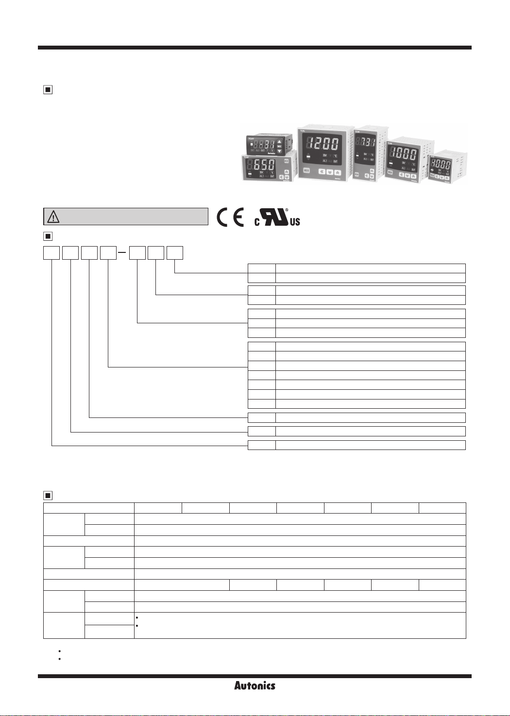
Ordering Information
-
Control output
L~
Power supply
Alarm output
Size
Digit
Setting type
Item
select.
2: It is unavailable for TC4SP, TC4Y.v
3: 11-pin socket (PG-11, PS-11(N)) for TC4SP: sold separately.
Specifications
AC power 100-240VACᜠ 50/60Hz
AC/DC power 24VACᜠ 50/60Hz, 24-48VDCᜡ
AC power Max. 5VA (100-240VACᜠ 50/60Hz)
AC/DC power Max. 5VA (24VACᜠ 50/60Hz), max. 3W (24-48VDCᜡ)
l
I
I
RTD DPt100Ω, Cu50Ω (allowable line resistance max. 5Ω per a wire)
Thermocouple K(CA), J(IC), L(IC)
RTD
※
1
Thermocouple
At room temperature (23
Out of room temperature range:
.
At room temperature (23
.
Out of room temperature range: (PV ±0.5% or ±2
※
For TC4SP, add ±1℃ by accuracy standard.
±5℃): (PV ±0.5% or ±2
℃
(PV ±0.5% or ±3
): (PV ±0.5% or ±1℃, select the higher one) ±1-digit
℃±5℃
℃, select the
℃, select the
'Mus
N Indicator - Without control output
R Relay output + SSR drive output
I I I
2 24VAC 50/60Hz, 24-48VDC
4 100-240VAC 50/60Hz
I I
I
N No alarm output
1 Alarm 1 output
2 Alarm 1 output + Alarm 2 output
S DIN W48×H48mm (terminal block type)
SP DIN W48×H48mm (11-pin plug type)
Y DIN W72×H36mm
M DIN W72×H72mm
H DIN W48×H96mm
W DIN W96×H48mm
L DIN W96×H96mm
4 9999 (4-digit)
C Set by touch switch
T Temperature controller
I
I
℃
higher one) ±1-digit
higher one) ±1digit
J
9.5×20.0
mm
I
, select the higher one) ±1-digit
;'.
> :
~,
>~;:
1
※
2
※
3
※
J
7.0×14.6mm 11.0×22 0mm
mm
I
:::
: :
I
I
~::
;:::
J-120
Autonics
Single Display, PID Control
Specifications
00
Series TC4S TC4SP TC4Y TC4M TC4W TC4H TC4L
Control
output
Alarm output AL1, AL2 Relay: 250VAC 1A 1a (※TC4SP, TC4Y have AL1 only.)
Control method ON/OFF and P, PI, PD, PID control
Hysteresis 1 to 100
Proportional band (P) 0.1 to 999.9
Integral time (I) 0 to 9999 sec
Derivative time (D) 0 to 9999 sec
Control period (T) 0.5 to 120.0 sec
Manual reset 0.0 to 100.0%
Sampling period 100ms
Dielectric
strength
Vibration 0.75mm amplitude at frequency of 5 to 55Hz (for 1 min) in each X, Y, Z direction for 2 hours
Relay
life cycle
Insulation resistance Over 100MΩ (at 500VDC megger)
Noise immunity Square-wave noise by noise simulator (pulse width 1us) ±2kV R-phase and S-phase
Memory retention Approx. 10 years (when using non-volatile semiconductor memory type)
Environment
Insulation type
Approval
Weight
2: The weight includes packaging. The weight in parenthesis is for unit only.
※
※
Environment resistance is rated at no freezing or condensation.
00
※
TC4 Series has selectable control output; Relay output, and SSR drive output. AC/DC power type does not have SSRP function.
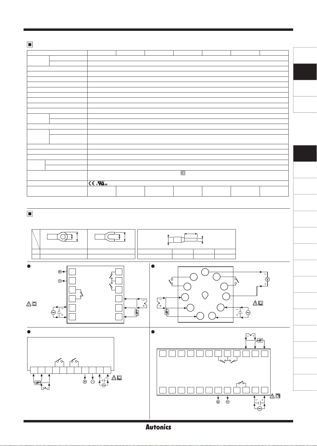
※
Use crimp terminals or teminals of size specied below.
~
TC4S
• •
&[QI
SOURCE:
100-240VAC
5VA 50/60Hz,
24VAC 5VA 50/60Hz,
24-48VDC 3W
TC4Y
• •
Relay 250VACᜠ 3A, 30VDCᜡ 3A, 1a
I
SSR 12VDCᜡ ±2V 20mA Max.
I
AC power 2,000VAC 50/60Hz for 1 min (between input terminal and power terminal)
I
AC/DC power 1,000VAC 50/60Hz for 1 min (between input terminal and power terminal)
I
Mechanical OUT: over 5,000,000 operations, AL1/2: Over 5,000,000 operations
I
Electrical
I
Ambient temperature -10 to 50℃, storage: -20 to 60
I
Ambient humidity 35 to 85%RH, storage: 35 to 85%RH
I
※
2
Connections
c:=rm]
<Round>
a Min. 3.0mm Min. 3.0mm
b Max. 5.8mm Max. 5.8mm
SSR OUT:
12VDC ±2V
20mA Max.
®
e
※
1
€~
AL1 OUT:
250VAC 1A 1a
□
□
BJ
□ □
□ □
Relay OUT:
250VAC 3A 1a
30VDC 3A 1a
OUT: over 200,000 operations (250VAC 3A resis ive load)
AL1/2: over 300,000 operations (250VAC 1A resistive load)
Double insula ion or reinforced insulation (mark:
and the power part: AC power 2kV, AC/DC Power 1kV)
CE
,'i\lus
Approx. 141g
(approx. 94g)
a
b
Cls
1
AL1 OUT:
250VAC 1A 1a
2
AL2 OUT:
250VAC 1A 1a
3
Relay OUT:
250VAC 3A 1a
4
30VDC 3A 1a
5
6
℃/℉ (
℃/℉
<Forked>
{a
to
I I
0.1 to 50.0
Approx. 123g
(approx. 76g)
I I
TI
10
□
11
12
a
7
8
9
℃/℉
b
Terminal number a b c
1 to N 6 Max. 1.9 Max. 4.0
11
B' RTD TC
B
A
SENSOR
) variable
℃
Approx. 174g
(approx. 85g)
TC4SP
Relay OUT:
250VAC 3A 1a
30VDC 3A 1a
TC4W
1 72 83 94 105 116
B'
BA
RTD
TC
SENSOR
※
1: AC power: 100-240VAC 5VA 50/60Hz
AC/DC power: 24VAC 5VA 50/60Hz, 24-48VDC 3W
SSR OUT:
12VDC ±2V
20mA Max.
SOURCE:
100-240VAC
※
1
5VA 50/60Hz,
24VAC 5VA 50/60Hz,
24-48VDC 3W
Autonics
I
@I
Approx. 204g
(approx. 133g)
I
c
~of7~
<Crimp terminal>
I
, Dielectric strength between the measuring input part
Approx. 194g
(approx. 122g)
I
a
b
(unit: mm)
I I
Approx. 194g
(approx. 122g)
I
Approx. 254g
(approx. 155g)
I
I I
6
5
4
RTD
TC
B'
3
B
2
A
SENSOR
13 16 19 22
14 17 20 23
15 18 21 24
1 4 7 10
2 5 8 11
□□□□□□□□
'-------~-----,-------,-.-----~
3 6 9 12
1
AL1 OUT:
250VAC 1A 1a
7
10
11
® e
SSR OUT:
12VDC ±2V
20mA Max.
8
9
AL1 OUT:
250VAC 1A 1a
※
1
&[QI
SOURCE:
100-240VAC
5VA 50/60Hz,
24VAC 5VA 50/60Hz,
24-48VDC 3W
SENSOR
TC
RTD
AL2 OUT:
250VAC 1A 1a
6
B A
B'
Relay OUT:
250VAC 3A 1a
30VDC 3A 1a
□□□
- +
le1
※
1
SENSORS
CONTROLLERS
MOTION DEVICES
SOFTWARE
(J)
Temperature
Controllers
(K)
SSRs
(L)
Power
Controllers
(M)
Counters
(N)
Timers
(O)
Digital
Panel Meters
(P)
Indicators
(Q)
Converters
SSR OUT:
12VDC ±2V
20mA Max.
(R)
Digital
Display Units
(S)
Sensor
Controllers
(T)
Switching
Mode Power
Supplies
(U)
Recorders
(V)
HMIs
(W)
Panel PC
(X)
Field Network
Devices
[g]
SOURCE:
100-240VAC
5VA 50/60Hz,
24VAC 5VA 50/60Hz,
24-48VDC 3W
J-121
TC Series
TC4M TC4H/L
•
1
□
2
□
3
□
®
※
e
1
-
+o
4
□
5
□
6
Relay OUT:
250VAC 3A 1a
8}
30VDC 3A 1a
7
8
□
9
SSR OUT:
12VDC ±2V
20mA Max.
&
[Q]
SOURCE:
100-240VAC
5VA 50/60Hz,
24VAC 5VA 50/60Hz,
24-48VDC 3W
※
1: AC power: 100-240VAC 5VA 50/60Hz
AC/DC power: 24VAC 5VA 50/60Hz, 24-48VDC 3W
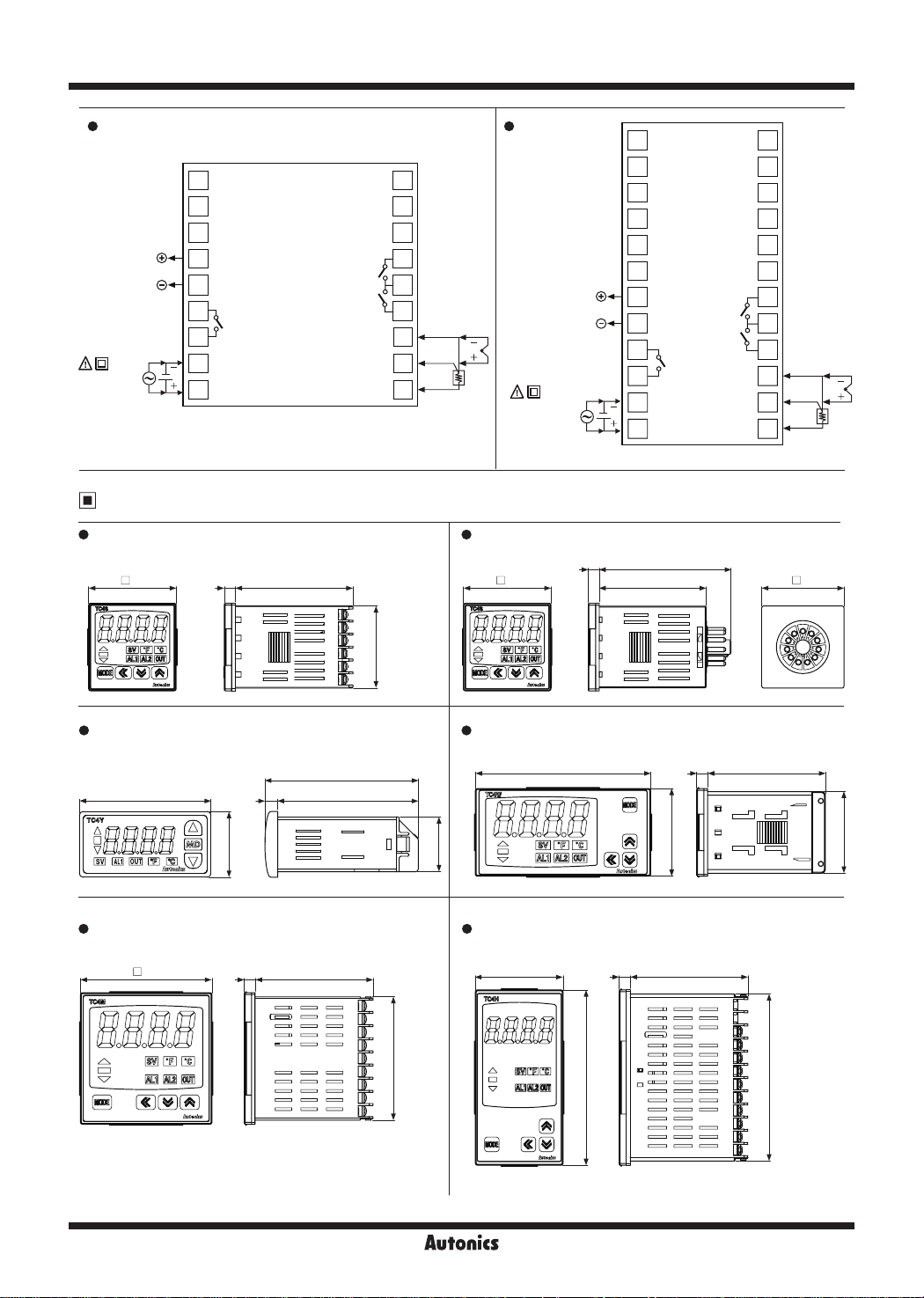
Dimensions
~
TC4S TC4SP
•
48
□
AL1 OUT:
250VAC
1A 1a
AL2 OUT:
250VAC
1A 1a
64.56 48 58 5 45
10
□
11
□
12
□
13
14
18
15
\o
B' RTD TC
16
□
B
17
□
A
18
SENSOR
□
•
•
□
SSR OUT:
12VDC ±2V
20mA Max.
&[Q]
SOURCE:
100-240VAC
5VA 50/60Hz,
24VAC 5VA 50/60Hz,
24-48VDC 3W
e
※
1
g:
6
®
1
□
2
□
3
□
4
□
5
□
6
□
7
□
8
□
9
8}
10
Relay OUT:
250VAC 3A 1a
30VDC 3A 1a
11
□
12
□
72.2
AL1 OUT:
250VAC
1A 1a
AL2 OUT:
250VAC
1A 1a
13
□
14
□
15
□
16
□
17
□
18
□
19
20
18
t{J
21
B' RTD TC
22
□
B
23
□
A
24
□
(unit: mm)
□
SENSOR
==
36
==
■
=
==
==
7
= = =
=
= = =
= = =
= = =
= = =
= = =
= = =
= = =
= = =
64.5
= =
•
30
UIS
D
"'
'v
~
TC4W
45
84
D
•
""
,,,
=
=
""
=
,,,
=
I
67 5
"""
ml
~
1118
TC4Y
•
72 77
TC4M TC4H
•
72 6
□
,.,..
lnl~f.il
IM,j][g
-
~
@@@@
L'>.
[nl
D
"v
[:f]IT]
~~IMI
~
@~
-
48
===
===
===
==
L,.
D
'v
111!11
~~
l!!lll!!llllll
~
@~
-
96
===
Ell===
o===
===
===;.,,
===
===
===
48
64.56
64.596 6
CD
c::::::'J
c,
.
C
c:::::;J c:::::;J
I
::::1:1
=
=
c::::::'J~
44.7
91.5
J-122
Autonics
Single Display, PID Control
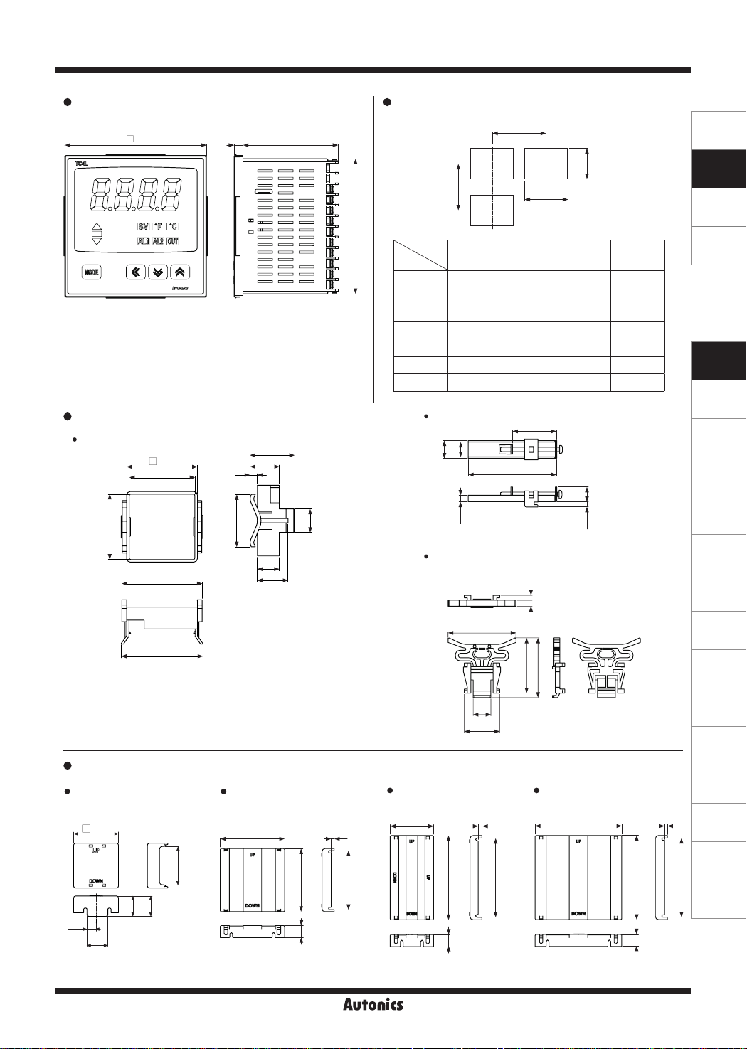
TC4L Panel cut-out
• •
64.5696
7
10IL
□
-
1111
,6.
D
v'
~
~
______
Bracket
TC4S/TC4SP Series
•
~l'l1'll'l:l
m~IMI
[!]00~
-
48.6
□
-
45
-
91.5
Size
Model
~
TC4S Min. 65 Min. 65 45
'
TC4SP Min. 65 Min. 65 45
TC4Y Min. 91 Min. 40 68
TC4M Min. 90 Min. 90 68
TC4H Min. 65 Min. 115 45
TC4W Min. 115 Min. 65 92
_L
31
20
5
TC4L Min. 115 Min. 115 92
TC4Y Series
•
12
A
D
B
A B C D
104.4
C
+0.6
0
+0.6
0
+0.7
0
+0.7
0
+0.6
0
+0.8
0
+0.8
0
30
60
45
45
31.5
68
92
45
92
SENSORS
CONTROLLERS
MOTION DEVICES
SOFTWARE
+0.6
0
+0.6
0
+0.5
0
+0.7
0
+0.8
0
+0.6
0
+0.8
0
(J)
Temperature
Controllers
(K)
SSRs
(L)
Power
Controllers
(M)
Counters
44 9
'•
55
56
Terminal cover (sold separately)
•
RSA-COVER
• •
(48×48mm)
48.4
□
~
9.8
22.5
[J .
41.5
18
22
36
RMA-COVER
(72×72mm)
ilill
~
(N)
3
86
Timers
(O)
Digital
Panel Meters
(P)
Indicators
(Q)
Converters
(R)
Digital
Display Units
(S)
Sensor
Controllers
(T)
Switching
Mode Power
Supplies
(U)
Recorders
(V)
HMIs
(W)
Panel PC
(X)
Field Network
Devices
16
TC4M, TC4W, TC4H, TC4L Series
15
21
•
3.34
11£
9
46
37.5
40.5
3.5 10
iT
12
u
23.9
RHA-COVER
• •
(48×96mm)
70
3
47.2
4
,._.,
68 5
ITT
13
64
91.5
I
~
13
86
RLA-COVER
(96×96mm)
94
,.
'
,.
M
--
[[h I I
-
CR
91 5
•~
'
m=l
13
Autonics
J-123
TC Series
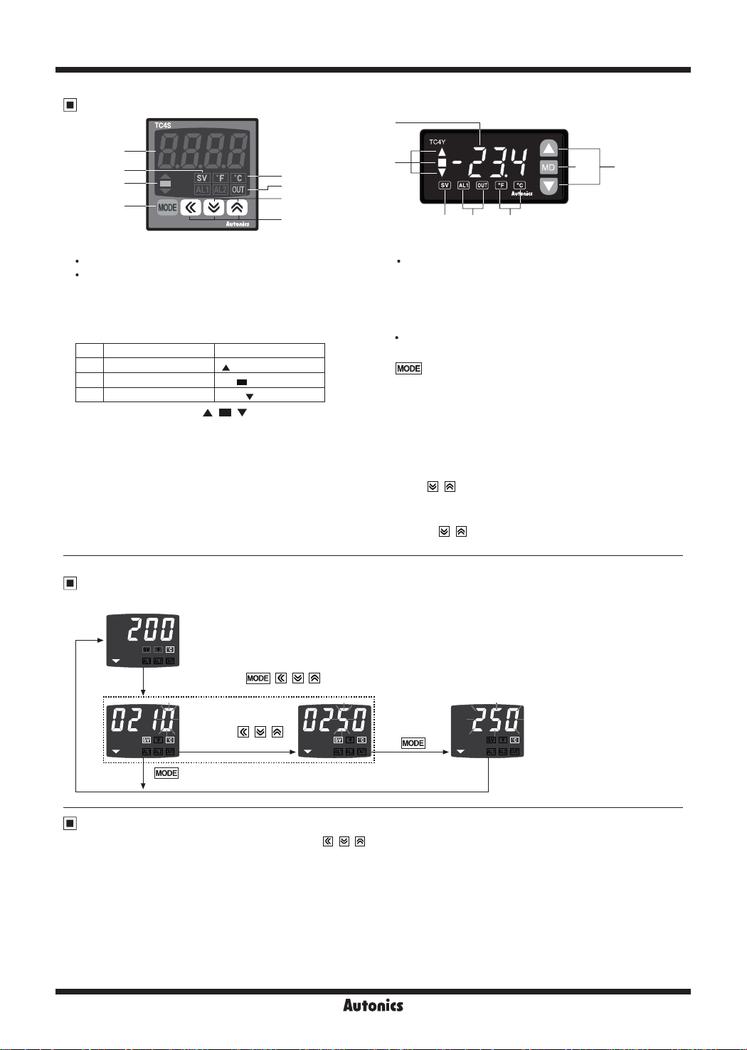
Unit Description
1
1
3
2
6
1. Present value (PV) display
RUN mode: Currently measured value (PV) display.
Parameter setting mode: Parameter or parameter
setting value display.
2. Deviation indicator, Auto-tuning indicator
It shows current temperature (PV) deviation based on set
temperature (SV) by LED.
No.
PV deviation temp. Deviation display
1
Over 2
℃
2
Below ±2
3
Under -2
I I
The deviation indicators ( , , ) flash by every 1 sec
when operating auto tuning.
3. Set temperature (SV) indicator
Press any front key once to check or change current set
temperature (SV), the set temperature (SV) indicator is
ON and preset set value is flashed.
4. Temperature unit
It shows current temperature unit.
℃
℃
(℃/℉)
indicator ON
indicator ON
indicator ON
I·
-.
.......
indicator
4
5
8
7
I
2
3 5 4
5. Control/alarm output indicator
OUT: It will turn ON when control output (Main Control
Output) is ON.
※
In case of CYCLE/PHASE control of SSR drive output,
it will turn ON when MV is over 3.0%. (only for AC
voltage type)
AL1/AL2: It will light up when alarm output Alarm 1/
6.
IMODEI
Used when entering into parameter group, returning
to RUN mode, moving parameter, and saving setting
values.
7. Adjustment
Used when entering into set value change mode, digit
moving and digit up/down.
8. FUNCTION key
Press
STOP, alarm output cancel, auto-tuning) set in inner
parameter [
※
Press
operation to move digit.
Alarm 2 are on.
key
+ keys for 3 sec to operate function (RUN/
].
DI K
+ keys at the same time in set value
6 7, 8
SV Setting
※
In case of changing set temperature from 210℃ to 250℃.
①
RUN mode (display a current temperature)
Press any key among
②
Set value change
mode change set
value by
keys.
④
Check SV
Parameter Reset
Reset all parameters as factory default. Hold the front + + keys for 5 sec, to enter parameter reset [
YES
'
' and all parameters are reset as factory default. Select ‘NO’ and previous settings are maintained. If setting parameter lock
LOC
[
] or processing auto-tuning, parameter reset is unavailable. (except TC4Y Series)
, , ,
, ,
~ ~ ~
③
Finish the setup.
INIT
] parameter. Select
J-124
Autonics
 Loading...