

Autonics TB42 Series Catalog Page
TB42 Series
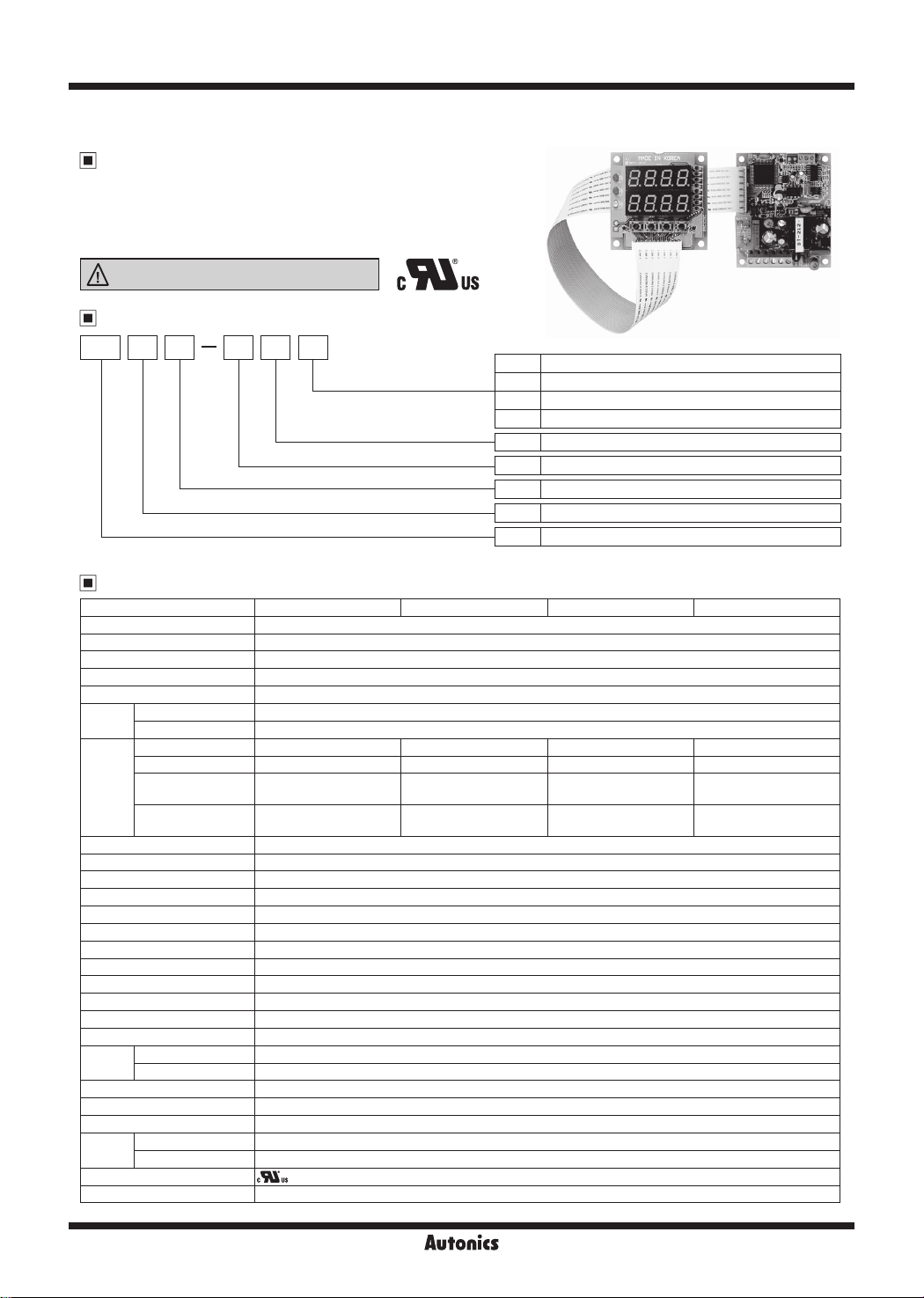
Board Type, Dual PID Control Temperature Controller
Features
● High quality and economical product
● Convenient organization of panel to use
● Dual PID control
● Time reservation
Please read “Safety Considerations” in operation
manual before using.
'-=I
&::;____
_____
Ordering Information
I c
TB 14 42 R
Control output
TL____+--+----~
Power supply
Sub output
Display
Digit
Item
※
1: PV transmission output type does not have Event 1 output.
'i\lus
R Relay output
S SSR drive output
C Current output (DC4-20mA)
N PV Transmission output (DC4-20mA)
4 100-240VAC 50/60Hz
1 Event 1 output type
2 2 Display
4 9999 (4-digit)
TB Temperature Controller Board
I
HIii/
ii
ii
jj/Jlj
,,,
If/
※
1
Specications
Model TB42-14R TB42-14S TB42-14C TB42-14N
Power supply 100-240VACᜠ 50/60Hz
Allowable voltage range 90 to 110 of rated voltage
Power consumption Max. 5VA
Display method 7-segment (PV: green, SV: red) LED method
Character size (W×H) 8×10
Input
type
Control
output
Sub output • Event 1 output: Relay output (250VACᜠ 0.5A 1a) • Event 2 output: OK monitoring display by LED
Control method ON/OFF control, P, PI, PD, PIDF, PIDS control
Set ing type Front push buttons
Display accuracy F.S ± 0.3% or 3℃, select he higher one
Hysteresis 1 to 100℃ (0.1 to 100.0℃) variable (at ON/OFF control)
Proportional band (P) 0.0 to 100.0%
Integral time (I) 0 to 3600 sec
Derivative time (D) 0 to 3600 sec
Control cycle (T) 1 to 120 sec
Sampling period 0.5 sec
Dielectric strength 2,000VAC 50/60Hz for 1 minute (Between input and power terminal)
Vibration 0.75mm amplitude at frequency of 10 to 55Hz (for 1 min) in each X, Y
Relay
life cycle
Insulation resistance Over 100MΩ (at 500VDC megger)
Noise immunity ±2kV the square wave noise (pulse width: 1㎲) by the noise simulator
Memory retention Approx. 10 years (when using non-volatile semiconductor memory type)
Environment
Approval
Unit weight Approx. 113.5g
※
H-138
RTD DPt100Ω, JPt100Ω [Allowable line resistance is max. 5Ω per a wire]
Thermocouple K(CA), J(IC) [Tolerance outer resistance is max. 100Ω]
Relay
SSR
Current
Transmission
Main output Mechanical: Min. 10,000,000, Electrical: Min. 100,000 (250V
I
Sub output Mechanical: Min. 20,000,000, Electrical: Min. 200,000 (250VAC 0.5A resistive load)
I
Ambient temperature -10 to 50℃, storage: -20 to 60
I
Ambient humidity 35 to 85%RH, storage: 35 to 85%RH
I
Environment resistance is rated at no freezing or condensa ion.
mm
250VACᜠ 3A, 12VDCᜡ 3A, 1a
-
- -
- - -
....
I
- - -
12VDCᜡ±3V 30mA Max.
℃
- -
DC4-20mA
(max. load 600Ω )
, Z direction for 2 hours
AC 3A resistive load)
Autonics
I
-
DC4-20mA
(Max. load 600Ω)

Board Type, Dual PID Control
Connections
※
RTD: DPt100Ω, JPt100Ω (3-wire type) ※Thermocouple: K(CA), J(IC)
※
Use crimp terminals of size specied below.
a
c
<Crimp terminal>
Terminal number a b c
1 to 3 4 to 5mm Max. 1.3mm Max. 3.3mm
4 to 9 6mm Max. 2.1mm Max. 4.2mm
RTD
T.C
SENSOR
Dimensions
Display part
•
Layout
•
I I
A
B
B'
0 I
00000000000000000000000
1.2
15.5 16.5
b
0
Power
[
Sub output
Main output
I
52
60
60
[
[
4-Ø4
0
52
60
100-240VAC 50/60
EVENT1:250VAC 0.5A 1a
Relay output
●CONTACT OUT:
250VAC 3A 1a
30VDC 3A 1a
RESISTIVE LOAD
Control part
•
---------L-------
SOURCE
-$-
Hz
SSR drive output Transmission outputCurrent output
●SSR OUT:
12VDC ±3V
30mA Max.
I
I
i
I
i
i
!
I
-$-
I
I
i
I
57
65
65
●Current OUT:
DC4-20mA
Load 600ΩMax.
-
-$-
--
70
78
-
-$:
4-Ø4
I
""------
●PV transmission OUT:
DC4-20mA
Load 600Ω Max.
(unit: mm)
(A)
Photoelectric
Sensors
(B)
Fiber
Optic
Sensors
(C)
Door/Area
Sensors
(D)
Proximity
Sensors
(E)
Pressure
Sensors
(F)
Rotary
Encoders
(G)
Connectors/
Connector Cables/
Sensor Distribution
Boxes/Sockets
(H)
Temperature
Controllers
(I)
SSRs / Power
Controllers
(J)
Counters
(K)
Timers
(L)
Panel
Meters
(M)
Tacho /
Speed / Pulse
Meters
(N)
Display
Units
(O)
Sensor
Controllers
(P)
Switching
Mode Power
Supplies
(Q)
Stepper Motors
& Drivers
& Controllers
(R)
Graphic/
Logic
Panels
(S)
Field
Network
Devices
Display part
60
※
Cable length is 300mm.
※
The size of board is based on user's application. (customizable)
Cable 20P
Length: 300
Autonics
Control part
(T)
Software
78
H-139

TB42 Series
Unit Description
1
2
3
4
---+-
5
8. 8. 8.
•
0
8. 8.
•
S1
[Q]
MD
El.
S2 S3 S4
[Ql]
[Q]
<(
~ ~
0
6
1. Mounting hole (Ø4.0mm)
2. Main output operation display LED (LED 1)
It indicates the operation status of control output and displayed on "LED 1".
But when it is current output or retransmission output "LED 1" does not operate. (LED indication is OFF)
3. Event 1 output operation display LED (LED 2)
It indicates the operating status of alarm output and displayed on "LED 2".
4. O.K monitor operation display LED (LED 3)
It indicates the operating status of alarm output and displayed on "LED 3".
After setting alarm output in Event 2, if execute Auto-tuning, O.K monitor operation will be displayed after AT function.
(it flashes during AT function, and turns OFF after completing AT function)
5. Mode key (S1)
It is used to enter into every parameter group or move to other parameters. It is "S1" on this PCB.
8 .
El
.
[Ql]
0
9
8
0
7
6. Shift key (S2)
It is used when change the setting value or move to digit at the parameter. It is "S2" on this PCB.
7. Up / Down key (S3/S4)
It is used when change the setting value or select setting function.
Up key is "S4" and Down key is "S3" on this PCB.
8. SV display part
The setting temperature is displayed in red LED.
But when timer function is used, the setting time will be displayed at
If time function is OFF, it will return to the setting temperature.
9. PV display part
It displays measured temperature in green LED.
Input Type and Range
Input sensor Display Temperature range (℃) Temperature range (℉)
Thermocouple
RTD
K(CA)
J(IC)
JPt H
JPt L
DPt H
DPt L
K CA
J IC
JPtH
JPtL
PT .H
PT .L
-100 to 1300 -148 to 2372
0 to 800 32 to 1472
0 to 500 32 to 932
-199.9 to 199.9 -199.9 to 392.0
0 to 500 32 to 932
-199.9 to 199.9 -199.9 to 392.0
T SV
.
H-140
Autonics
 Loading...