

DRW170788AA
Autonics
BOARD TYPE TEMPERATURE CONTROLLER
TB42 SERIES
I N S T R U C T I O N M A U A L
Please read the following safety considerations before use.
Safety Considerations
※
Please observe all safety considerations for safe and proper product operation to avoid hazards.
※
Safety considerations are categorized as follows.
Warning Failure to follow these instructions may result in serious injury or death.
Caution
※
The symbols used on the product and instruction manual represent the following
symbol represents caution due to special circumstances in which hazards may occur.
Warning
A
1. Fail-safe device must be installed when using the unit with machinery that may
cause serious injury or substantial economic loss. (e.g. nuclear power control,
medical equipment, ships, vehicles, railways, aircraft, combustion apparatus, safety
equipment, crime/disaster prevention devices, etc.)
Failure to follow this instruction may result in re, personal injury, or economic loss.
2. Install on a device panel to use.
Failure to follow this instruction may result in electric shock or re.
3. Do not connect, repair, or inspect the unit while connected to a power source.
Failure to follow this instruction may result in electric shock or re.
4. Check 'Connections' before wiring.
Failure to follow this instruction may result in re.
5. Do not disassemble or modify the unit.
Failure to follow this instruction may result in electric shock or re.
Caution
1. When connecting the power input and relay output, use AWG 20(0.50mm2) cable or
over, and connecting the sensor input and communication cable without dedicated
cable, use AWG 28~16 cable.
Failure to follow this instruction may result in re or malfunction due to contact failure.
2. Use the unit within the rated specications.
Failure to follow this instruction may result in re or product damage.
3. Use dry cloth to clean the unit, and do not use water or organic solvent.
Failure to follow this instruction may result in electric shock or re.
4. Do not use the unit in the place where ammable/explosive/corrosive gas, humidity,
direct sunlight, radiant heat, vibration, impact, or salinity may be present.
Failure to follow this instruction may result in re or explosion.
5. Keep metal chip, dust, and wire residue from owing into the unit.
Failure to follow this instruction may result in re or product damage.
Dimensions
● Display board ● Control board
(Unit:mm)
Parameter
C SV
EV 1 10
lIJ
EV 2 10
ll~
T SV 0.1
STSP 0
t
i
I
w
※
i
t
t
s
e
t
i
I
w
※
r
v
e
e
Flow chart for rst setting group
i::r~
c
n
O
※
i
s
u
n
e
h
T
※
t
n
e
E
※
x
a
●
E
m
~
.•
Oi
-~
e
h
W
t
p
e
m
i
t
t
s
e
n
i
l
s
d
p
~
The above specications are subject to change and some models may be discontinued
※
without notice.
Be sure to follow cautions written in the instruction manual and the technical
※
descriptions (catalog, homepage).
Thank you for choosing our Autonics product.
Failure to follow these instructions may result in personal injury or product damage.
60
4
4
60
4-ø4 0
4
65
78
4
0
-
u
n
R
y
e
K
o
T
i
t
t
t
r
s
e
s
F
c=J
c=J
l
l
t
r
r
t
e
n
u
o
R
U
i
r
/
r
h
g
n
p
u
o
g
T
l
l
t
r
r
t
e
n
u
o
R
U
i
t
t
r
y
s
e
g
n
u
o
g
K
RUN
C-SV 0
EV-1 10
EV-2 10
]~----
T-SV 0.1
STSP 0
i
t
t
r
e
n
e
n
e
o
s
t
t
r
g
r
a
e
p
e
u
e
m
i
l
r
v
n
e
u
v
e
a
e
i
t
r
r
e
g
n
a
a
p
m
l
i
f
t
t
p
e
o
s
n
e
g
~
sv
'
"lfl@B
t
t
r
n
r
e
h
c
n
e
u
t
r
r
a
e
e
u
d
n
a
l
r
g
v
e
u
e
a
a
,
r
y
a
s
s
e
d
p
e
.
k
y
e
c
u
h
i
r
n
g
o
u
g
p
0
ll~
il~
RSET 0.0 PIDT 0002
'······~
,
i
f
r
e
d
o
s
s
e
p
N
m
i
t
t
.
r
d
s
e
g
n
p
u
o
g
,
i
f
e
d
o
N
m
i
r
s
o
p
p
y
e
c
u
o
T
S
V
e
T
m
i
h
T
i
h
T
I
※
n
i
h
T
i
h
T
I
※
n
h
W
h
T
I
※
h
T
:
0
:
2
i
t
t
e
g
n
m
s
s
n
e
o
i
t
t
y
s
e
n
i
r
s
o
n
e
t
r
p
e
e
m
..•
0~
.,
-
"
S
C
V
i
n
P
V
l
i
s
p
d
a
t
.
r
p
a
T
k
e
s
r
f
f
e
f
i
g
t
liil
t
o
n
k
y
e
u
o
i
r
.
s
s
e
g
g
n
h
(
i
t
t
l
s
e
g
n
v
e
u
a
t
r
r
r
a
e
p
e
n
a
u
i
f
r
o
d
s
e
o
s
e
m
i
t
t
r
s
n
e
g
g
d
o
u
y
o
s
r
d
o
e
s
N
O
o
r
a
p
t
l
r
o
s
u
e
a
A
m
t
l
i
b
e
s
y
p
e
d
a
d
i
f
r
o
d
s
e
o
s
e
m
i
t
t
r
s
n
e
g
g
o
u
p
t
l
r
y
o
s
u
e
a
A
m
t
l
i
b
e
s
y
p
e
d
a
d
i
t
i
s
e
d
s
a
u
n
t
t
r
f
a
n
g
e
s
e
o
l
t
i
"
"
c
s
e
e
0
n
S
i
f
r
a
t
s
e
d
o
o
m
i
r
f
o
e
T
c
n
u
m
t
t
u
u
p
c
s
e
o
m
,
t
i
e
d
e
h
c
e
d
m
t
i
'
t
u
b
s
e
o
d
n
i
f
t
s
e
d
o
c
a
m
i
l
l
i
t
v
n
e
b
a
a
r
-
(
:
)
u
e
S
C
V
E
~
SN
:a
i
l
i
"
s
s
y
p
d
e
a
d
i
t
,
r
"
"
s
p
a
0
i
y
e
d
n
S
V
r
h
e
n
s
p
s
e
.
y
.
y
e
s
5
K
c
e
i
t
t
o
c
e
n
S
AT OFF I NT
c=J
P 3.0 H SC 400
c=J
I 0
r
d
e
s
n
g
o
u
g
p
T
L SC 0
D 0 UNIT ?C
T 20
IN B 0
c=J
HYS 2
c=J
f
r
k
c
)
g
t
t
.
o
p
.
t
.
o
p
.
s
i
n
t
s
e
i
t
o
t
i
o
r
a
x
1
S
d
o
.
i
y
e
o
s
5
c
e
n
c
e
S
o
f
r
d
e
h
o
0
9
s
c
e
d
n
o
d
i
.
t
t
s
e
d
o
e
g
n
m
i
f
i
i
i
e
T
t
T
r
t
o
s
S
V
i
t
n
p
g
e
m
r
p
e
e
a
m
i
t
r
e
o
a
n
a
i
t
n
p
g
e
m
r
p
e
a
m
e
i
t
r
e
o
a
n
a
f
i
r
t
u
e
m
i
i
t
s
e
g
m
i
t
t
s
e
S
P
l
i
t
c
e
g
n
,
:
n
o
1
C
t
t
f
r
u
a
e
i
l
t
n
o
p
a
l
f
n
c
n
e
u
e
i
f
y
s
c
e
p
i
i
s
n
s
s
m
l
p
a
e
o
m
o,
~-
-~
- ~
@"
~...,_..._~O
0
l
l
l
f
i
0
w
.
t
r
a
p
V
i
t
i
t
s
o
g
e
t
k
y
e
w
t
r
r
s
e
o
d
e
t
u
s
e
t
u
s
n
n
g
i
t
u
s
c
i
c
o
f
sa
i
c
M
t
o
e
u
p
n
n
h
w
t
r
r
f
l
u
a
e
o
a
A
r
r
f
e
a
n
g
o
e
E
-
i
L
0
A
-
n
E
V
t
r
r
f
l
u
a
e
o
a
A
r
r
f
e
a
n
g
o
e
E
-
i
L
0
A
-
n
E
V
i
i
,
t
t
s
h
c
o
n
m
t
.
.
o
9
9
1
9
9
0
i
,
t
s
h
o
d
e
m
r
f
i
t
e
c
n
u
o
m
t
t
t
f
f
u
o
u
p
o
t
t
i
t
p
o
e
h
e
m
i
l
n
a
s
e
b
d
a
p
t
f
n
o
e
h
c
n
u
i
t
.
a
n
o
t
t
t
n
u
o
y
u
p
p
i
t
t
s
n
e
g
1
0
0
"1-1
i
r
n
k
e
C
t
v
o
e
e
h
w
r
y
s
b
s
e
p
t
i
t
i
s
e
n
m
.
t
0
0
1
℃
EV 1 AL 1
AL T AL A
d
n
EV 2 AL S
i
r
g
n
u
LOC OFF
t
r
f
e
g
n
a
o
c
a
e
h
s
e
i
t
r
r
o
p
e
o
a
n
s
h
a
i
i
t
s
w
i
r
h
T
d
t
r
e
a
i
i
s
w
i
r
h
T
d
i
f
s
o
t
i
u
n
d
e
w
t
r
s
o
r
s
e
e
,
h
w
Iii@@"
g
e
1
0
i
r
s
s
e
r
s
s
e
b
e
i
i
t
r
h
n
n
p
u
i
t
t
r
s
n
e
g
g
o
i
o
n
s
h
a
b
e
i
i
t
t
r
h
n
n
p
u
i
t
t
r
s
n
e
g
g
o
i
t
t
t
r
n
g
s
e
i
.
r
s
o
u
H
l
l
i
t
b
e
n
o
d
t
i
t
p
e
h
e
m
i
t
v
a
n
o
v
a
i
i
i
c
s
h
s
d
p
fJ'
2
t
"
"
o
1
,
y
k
e
n
g
.
y
k
e
m
-
1
V
f
1
o
r
o
p
m
-
2
V
f
2
o
o
d
e
t
h
e
o
m
.
n
t
f
a
e
.
(
R
y
d
e
i
t
.
n
o
.
e
.
℃
.,.~
Oi
-~
=0----u.~O
h
a
n
i
t
h
p
h
e
n
p
h
n
e
a
e
a
h
a
0
4-ø4 0
s
5
+
c
e
i
i
t
r
t
s
r
e
d
n
g
g
K CA
c=J
c=J
c=J
c=J
c=J
c=J
c=J
c=J
c=J
c=J
.
r
s
o
i
t
s
-
n
e
n
n
g
u
p
n
n
u
p
e
i
s
.
l
i
l
a
N
s
E
f
E
1
V
o
f
s
e
n
c
o
e
e
h
a
o
d
e
m
w
,
i
t
s
h
i
t
s
-
e
n
f
E
2
V
o
f
s
e
n
g
c
o
e
e
h
a
,
i
t
s
h
o
d
e
m
w
i
i
f
t
s
n
g
e
u
o
m
.
l
y
e
d
p
a
l
)
e
b
a
y
r
d
e
y
b
e
g
n
a
.,.~
o,
-~
"
il'lsa
=0--u.--~O
l
o
v
w
S
e
u
V
a
,
t
t
v
o
e
n
e
h
e
m
i
-
r
1
s
s
e
y
b
p
V
i
k
n
y
e
a
g
a
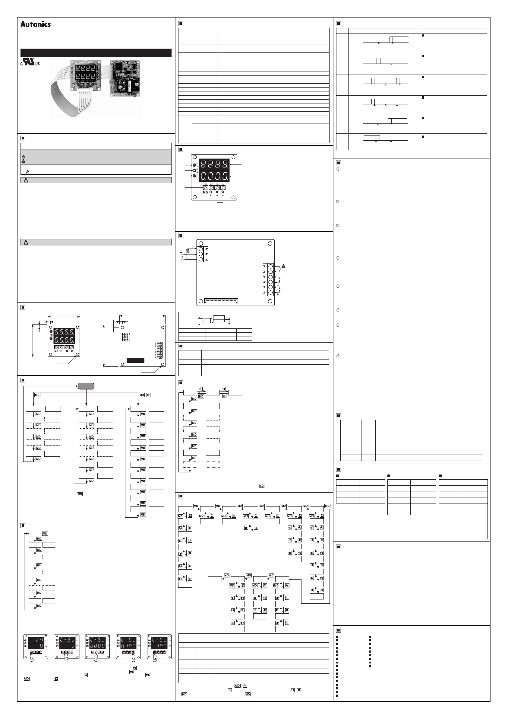
Specications Operation chart for alarm output
Model TB42
Power supply 100-240VACᜠ 50/60Hz(90 to 110% of rated voltage)
Allowable voltage range 90 to 110 of rated voltage
Power consumption Approx. max. 5VA
Display method 7-segment (PV: green, SV: red) LED method
Character size (W×H) 8×10mm
Input sensor
Control method • ON/OFF control(Hysteresis is adjustable) • P, PI, PD, PIDF, PIDS
Control output
Retransmission output 4-20mADC, Load 600Ω max. for PV
Sub output
Setting method Setting by front push buttons
Display accuracy ±0.3% rdg based on F S or 3℃ Max.
Adjustment sensitivity Adjustable 1 to 100℃(0.1 to 100.0℃) at ON / OFF control
Proportional band(P) 0.0 ~ 100.0%
Integral time( I ) 0 ~ 3600sec
Derivative time(D) 0 ~ 3600sec
Control cycle(T) 1 ~ 120sec
Sampling time 0.5sec. xed
Main output
Relay
life cycle
Sub output
Memory retention 10 years
Ambient temperature
Environ
-ment
Ambient humidity
• Thermocouple : K(CA), J(IC) (Tolerance of outer resistance is max. 100Ω)
• RTD : Pt100Ω 3 wires(Allowable line resistance is max. 5Ω per a wire)
• Relay contact output:250VACᜠ 3A 1a • SSR output:12VDC ±3V Load 600Ω min.
• Current output:4-20mADC, Load 600Ω max.
• EVENT 1 output : Relay contact output(250VACᜠ 0.5A 1a)
• EVENT 2 output : OK monitor operation display by LED
Mechanical:Min.10,000,000 times
Electrical:Min.100,000 times(250VAC 3A resistive load)
Mechanical:Min.20,000,000 times
Electrical:Min.200,000 times(250VAC 0.5A resistive load)
-10 ~ 50℃, Storage: -20 ~ 60
35 ~ 85%RH
℃
Front panel identication
1
2
3
4
5
0
5. MD key t is used to enter into every setting group or move to other setting mode.
6. Shift key It is used when change the setting value or move to digit at setting mode.
7. Up/Down key t is used when change the setting value or select setting function.
8. C-SV display The setting temperature is displayed in red. But when timer function is used, the setting
9. PV display It displays measured temperature in green.
6 7
time will be displayed, if time function is OFF, it will return to the setting temperature.
1. Mounting hole
2. Main output operation display LED
t indicates the operation status of control output and
9
displayed on "LED 1". But when it is current output
(TB42-14C) or Retransmission output(TB42-14N),
"LED 1" doesn't operate. (LED indication is OFF)
8
3. EVENT 1 output operation display LED
t indicates the operating status of alarm output and
displayed on "LED 2".
4. O.K monitor operation display LED
t indicates the operating status of alarm output and
0
displayed on "LED 3".
After setting alarm output in EVENT 2, if execute
autotuning, O K monitor operation will be displayed
after AT function.
Connections
RTD
A
T.C
SENSOR
※
Use crimp terminals of size specied below.
Terminal number a b c
1 to 3 4 to 5 Max. 1 3 Max. 3.3
4 to 9 6 Max. 2.1 Max. 4.2
1
B
2
B'
3
0
j·······················II
a
c
<Crimp terminal>
I I
b
(unit: mm)
Terminal
of input,
output
0
9
100-240VAC 50/60Hz 5VA
8
EVENT 1:
7
250VAC 0.5A CONTACT
6
• CONTACT OUT: (TB42-14R)
5
250VAC 3A 1a RESISTIVE LOAD
4
• SSR OUT: (TB42-14S)
12VDC ±3V Load 600Ω Min.
• Current OUT: (TB42-14C)
DC4-20mA Load 600Ω Max.
SOURCE
Alarm output
Mode
AL A
AL B
AL C
AL D
Operation Function
General Alarm No optional alarm output.
Alarm Latch When alarm output turns on once, the output will keep ON continuously.
Standby Alarm
Alarm Latch &
Standby Alarm
It doesn't output at rst operation. (When it reaches to rst object value)
It operates Alarm Latch & Standby Alarm at the same time.
Flow chart for second setting group
i
i
l
f
i
t
t
r
o
u
p
.
r
s
o
i
l
l
.
r
s
o
i
l
l
.
f
o
sv
i
s
t
o
g
n
.
s
h
s
e
d
o
AT
: :
J~
,
l~
REST
s=
HYS 2
l
y
n
P
O
※
o
y
S
H
m
※
l
s
e
u
a
V
※
t
r
e
n
u
R
※
i
t
r
n
n
e
E
※
Flow chart for third setting group
Temp. sensor
mode
IN-T
KCA
OFF ON
P 3.0
CJ
I 0
D 0
T 20
0.0
CJ
y
e
d
o
d
n
a
S
H
m
l
l
i
t
o
n
e
b
e
d
w
i
r
i
t
n
t
v
e
y
e
s
e
R
U
a
p
o
N
m
t
r
e
a
m
Scale
(High-limit)
H-SC
400
n
e
d
i
r
e
t
o
g
i
h
T
I
f
"
P
i
h
T
h
e
T
i
h
T
h
e
T
h
T
e
h
T
i
h
T
r
p
o
t
s
a
h
T
e
h
T
e
d
o
m
i
l
s
d
y
a
p
e
d
o
g
m
l
l
a
m
i
n
t
s
o
n
v
a
Scale
(Low-limit)
L-SC0UNIT
T
r
o
i
f
r
s
s
s
i
s
n
i
w
e
o
a
o
s
o
d
s
e
m
"
m
r
m
r
s
r
m
p
o
d
s
r
i
d
i
s
d
l
i
e
l
.
i
"
"
v
0
a
0
s
u
e
i
f
o
r
d
s
e
o
s
e
i
f
t
t
a
n
g
e
o
s
n
e
i
f
r
s
o
d
e
o
s
e
i
f
t
t
a
n
g
e
o
s
n
e
i
f
r
s
s
e
d
o
o
m
f
i
t
t
e
g
n
a
o
s
e
i
f
o
r
d
s
e
o
c
o
i
t
l
r
t
r
o
n
a
c
o
o
n
r
i
.
a
s
d
5
0
%
i
f
r
s
s
e
d
o
o
m
f
i
t
t
e
g
n
a
o
s
e
l
i
l
l
s
e
b
d
y
a
p
e
,
,
I
n
e
h
P
P
w
f
t
r
c
a
y
o
s
c
e
p
s
e
n
e
h
s
u
p
w
i
l
t
r
n
e
b
a
s
n
a
Unit mode
JIC
JPT.H
JPT.L
PT .H
Temp. sensor
mode
IN-T
When it sets PIdt
0001:Heat-function operation PIdF
0002:Heat-function operation PIdS
0003:Cool-function operation PIdF
0004:Cool-function operation PIdS
Lock
mode
LOC
o
m
l
f
.
I
t
t
s
o
n
c
e
e
i
t
t
r
t
n
p
r
g
o
p
o
i
t
,
s
c
b
o
e
e
m
i
t
t
i
t
r
n
g
e
g
n
a
i
t
s
g
0
o
3
6
0
i
i
t
t
t
i
r
n
d
v
g
e
a
i
t
s
g
0
o
3
6
0
i
t
t
l
e
g
n
c
y
c
e
i
t
s
g
n
1
o
2
1
i
t
p
s
n
e
a
g
n
m
l
i
.
s
s
e
h
u
d
T
i
t
t
t
r
e
g
n
s
y
h
e
i
t
s
g
n
1
o
0
1
/
t
d
a
F
N
O
O
,
I
c
P
n
o
P
D
D
i
i
f
i
t
.
c
a
n
o
i
k
g
n
a
h
i
i
t
s
s
n
o
u
o
p
m
?C
?F
Event 2
EV-2
PT.L
OFF
LOC1
LOC2
AL-0
AL-3
AL-4
ALL
IN T KCA
H SC 400
L SC 0
UNIT ?0
IN B 0
PIDT 2
EV 1 AL 1
AL T AL A
EV 2 AL S
LOC OFF
l
l
t
i
I
t
r
e
u
w
※
n
e
h
S
V
W
※
k
y
e
a
~
f
I
t
o
n
k
y
e
※
Select one input sensor among 6 kinds.
Setting High-limit of temperature. Setting range is within input range of each sensor.
Setting Low-limit of temperature. Setting range is within input range of each sensor.
Setting the unit of temperature and select between ℃ or ℉.
It is compensating the allowance occurred in input sensor.
The range of setting is -50 to 50℃(Decimal type : -50.0 to 50.0℃).
Select PID control type among 4 kinds.
Select Alarm output function of EVENT1 among 7 kinds.
Select Alarm output option function among 4 kinds.
Select Alarm output function of EVENT2 among 3 kinds.
Set whether it is locked or not of setting value among 4 kinds.
r
t
n
e
d
o
y
b
o
R
i
i
l
f
s
k
c
o
d
n
m
c
u
o
d
e
h
p
U
N
M
r
r
d
e
s
e
s
e
y
b
p
t
v
t
r
e
o
o
o
e
h
M
f
r
.
i
o
s
0
9
c
e
n
+
f
r
i
r
s
s
e
g
n
i
,
k
y
e
i
g
n
r
e
d
s
s
e
y
b
p
i
t
c
a
e
t
h
s
e
g
n
y
e
o
K
s
5
c
e
i
t
s
b
a
i
g
n
d
o
m
o
l
t
e
t
t
o
s
e
e
h
v
i
.
k
y
e
n
a
g
a
,
i
l
l
t
i
t
r
e
r
e
n
u
w
s
c
e
e
,
n
o
T
A
i
l
o
n
a
b
a
/
F
N
O
O
i
.
l
I
t
e
m
.
c
s
0
e
i
t
e
v
e
m
.
c
s
0
e
f
t
o
c
n
o
.
0
s
c
e
i
i
t
v
o
d
a
e
r
e
a
n
g
e
i
s
e
s
w
.
0
℃
t
r
c
F
n
o
i
l
t
r
s
u
o
f
r
y
e
o
t
t
y
u
e
p
Input
correction
IN-B0PIDT
i
n
d
n
a
e
l
e
u
y
b
a
t
o
R
U
N
g
n
f
n
u
n
d
c
o
F
I
"
f
"
.
I
f
l
.
r
o
,
n
f
o
n
e
h
l
.
o
s
e
s
5
e
.
Alarm
mode
AL-T
AL-A
AL-B
AL-C
AL-D
c
h
r
e
p
o
M
o
"
w
s
d
c
s
s
w
c
f
n
s
i
D
e
i
.
.
e
s
d
h
i
t
o
"
P
t
r
0
"
i
c
h
t
t
i
t
s
t
t
i
n
.
e
e
h
n
w
"
v
l
f
o
u
,
i
t
h
i
,
s
0
i
s
h
i
n
g
s
u
PID
selection
0001
0002
0003
0004
i
g
n
M
g
r
e
o
l
l
i
s
l
a
u
e
i
t
c
n
f
s
u
i
t
s
h
c
c
o
i
.
s
0
d
e
O
d
o
,
℃
No alarm output.
Deviation High-limit alarm
■
If deviation between PV and SV is occurring
higher than deviation temperature setting value,
the output will be ON.
The deviation temperature is set in EV-1 of rst
setting group.
Deviation Low-limit alarm
■
If deviation between PV and SV is occurring
lower than deviation temperature setting value,
the output will be ON.
The deviation temperature is set in EV-1 of rst
setting group.
Deviation High/Low-limit alarm
■
If deviation between PV and SV is higher or
lower than deviation temperature setting value,
the output will be ON.
The deviation temperature is set in EV-1 or EV-2
of rst setting group.
Deviation High/Low-limit reverse alarm
■
If deviation between PV and SV is higher or
lower than deviation temperature setting value,
the output will be OFF.
The deviation temperature is set in EV-1 or EV-2
of rst setting group.
The absolute value High-limit alarm
■
If PV is equal or higher than alarm temperature
setting value, the output will be ON. The
deviation temperature is set in EV-1 of rst
setting group.
The absolute value Low-limit alarm
■
If PV is equal or lower than alarm temperature
setting value, the output will be ON. The alarm
temperature is set in EV-1 of rst setting group.
-
AL 0
OFF
"
ON
"
I I
ON
11
℃
OFF
"
℃
er:=
PV 110
=IJ
ON
b
-
℃
"
℃
℃
AL 1
AL 2
AL 3
AL 4
AL 5
AL 6
"b" means xed 2℃ as interval between ON and OFF when alarm output is operating.
※
OFF
-
When set 10℃ in EV-1 as deviation temperature.
※
When set 10℃ in EV-1 as deviation temperature.
※
When set 10℃ in EV-1(EV-2) as deviation temperature.
※
When set 10℃ in EV-1(EV-2) as deviation temperature.
※
When set 110℃ in EV-1 as alarm temperature.
※
When set 90℃ in EV-1 as alarm temperature.
※
SV 100℃PV 110
ON b
11
PV 90℃SV 100
ON ON
b b
=IJ
PV 90
℃
OFF OFF
b b
a:=
PV 90℃SV 100℃PV 110
OFF
-
SV 100℃PV 110
ON OFF
b
11
PV 90℃SV 100
Functions
EVENT function
● This function can execute as main control output and sub function as well.
● EVENT1 output is relay contact consisted of 250VAC and 0.5A 1a.
There are 7 setting mode include deviation alarm and absolute alarm.
The operation of EVENT1 output is displayed on LED2 at front.
● There is no terminals for EVENT2 output, it is operating as O.K monitor operation at AL-3,
AL-4 displayed in LED 3 at front.
Autotuning function
P D Autotuning function is automatically to measure thermal characteristics and response of
the control object and then execute its value under high response & stability after calculating
the time constant of P D required to control optimum temperature. When AT function is started,
LED3 will icker and when LED3 is OFF this operation will stop.
Dual PID control function
One is that PV is reached at SV with fast response speed, but a little of overshoot is occurred,
the other is that PV is reached at SV with slow response speed, but overshoot will be minimized.
1)P DF(PID fast) : This mode is applied at the machines or systems which requite stop fast
2)P DS(PID slow) : This mode is applied at the machine which overshoot must not be occurred,
Retransmission output(PV)
This function is to transmit the current value(PV) to external equipment such as PC or recorder
etc. the output is 4-20mADC and cannot be used with control output at the same time. It
will output 20mA, when PV reaches to the temperature in H-SC, and output 4mA, when PV
reaches to the temperature in L-SC.
Resolution is 16,000 division. (TB42-14N)
Error indication
If an error is occurred while the controller is operating, it will be displayed as follow.
1)"LLLL" is ickering when measured input temperature is lower than input range of the sensor.
2)"HHHH" is ickering when measured input temperature is higher than input range of the sensor.
3)"oPEn" is ickering when the input sensor is not connected or its wire is cut.
Manual reset(rESt)
Proportional control has an offset because rising time is not the same as falling time, even if
the unit operates normally. This function is to correct offset.
Lock function
Setting value cannot be changed by unauthorized person. There are 4kinds of lock mode in
this unit.
1)"OFF" : All modes can be changed.
2)"Loc1" : All modes except Second setting group, Third setting group.
3)"Loc2" : All modes except C-SV.
4)"All" : All modes can not be changed.
Timer function(t-Sv)
● There is no output terminal in this function, it controls main output by setting of Timer function.
● Timer function
When set "0000" in StSP mode : It will not be the Timer function.
①
In this case it doesn't display t-SV mode.
When set "0001" in StSP mode : It is controlling temperature during the time is set in t-SV.
②
Ex)If set 5.0 to t-SV, it will stop after controlling for 5 hours.
When set "0002" in StSP mode : After set the time in "t-SV", it starts to control temperature.
t
r
t
t
a
e
p
s
e
u
a
o
n
t
a
f
o
c
n
f
u
0
u
.
t
r
t
.
.
r
1
o
0
0
0
0
o
m
n
i
i
t
l
l
o
n
b
e
w
F
O
i
i
l
l
t
c
u
n
o
n
b
e
w
r
r
e
d
h
e
n
w
a
n
d
t
.
o
1
0
0
0
%
/
N
l
t
r
c
F
F
n
o
o
O
③
i
g
n
0
%
.
F
F
O
.
Ex)If set 5.0 to t-SV, it will start to control after 5 hours.
● When need to stop timer during operation, move to StSP mode and set "0000".
● When timer function is used, the time has been set in "t-SV" will be displayed in SV display
.
of RUN mode.
Input specication and temperature range
Input sensor Display Selectable temperature range ℃Selectable temperature range
.
F
K(CA)
J(IC)
JPtH
JPtL
DPtH
DPtL
Factory default
~
First setting group Second setting group Third setting group
■
C-SV 0
EV-1 10
EV-2 10
Event 1
STSP 0
EV-1
AL-0
n
e
h
W
※
r
p
u
o
g
AL-1
AL-2
AL-3
AL-4
AL-5
AL-6
e
t
k
r
y
e
s
n
e
h
s
e
p
Cautions during Use
1. Follow instructions in 'Cautions during Use'. Otherwise, It may cause unexpected accidents.
2. Check the polarity of the terminals before wiring the temperature sensor.
For RTD temperature sensor, wire it as 3-wire type, using cables in same thickness and length.
For thermocouple (CT) temperature sensor, use the designated compensation wire for extending wire.
3. Keep away from high voltage lines or power lines to prevent inductive noise.
In case installing power line and input signal line closely, use line lter or varistor at power line and
shielded wire at input signal line.
Do not use near the equipment which generates strong magnetic force or high frequency noise.
4. Install a power switch or circuit breaker in the easily accessible place for supplying or disconnecting
the power.
5. Do not use the unit for other purpose (e g. voltmeter, ammeter), but temperature controller.
6. Make a required space around the unit for radiation of heat.
For accurate temperature measurement, warm up the unit over 20 min after turning on the power.
7. Make sure that power supply voltage reaches to the rated voltage within 2 sec after supplying power.
8. Do not wire to terminals which are not used.
9. This unit may be used in the following environments.
Indoors (in the environment condition rated in 'Specications')
①
Pollution degree 2
③
Major Products
Photoelectric Sensors Temperature Controllers
Fiber Optic Sensors Temperature/Humidity Transducers
Door Sensors SSRs/Power Controllers
Door Side Sensors Counters
Area Sensors Timers
Proximity Sensors Panel Meters
Pressure Sensors Tachometer/Pulse (Rate) Meters
Rotary Encoders Display Units
Connector/Sockets Sensor Controllers
Switching Mode Power Supplies
Control Switches/Lamps/Buzzers
I/O Terminal Blocks & Cables
Stepper Motors/Drivers/Motion Controllers
Graphic/Logic Panels
Field Network Devices
Laser Marking System (Fiber, Co₂, Nd: YAG)
Laser Welding/Cutting System
response speed, and allowable a little overshoot which requite.
because the re can be and allowable low response time.
KCA
JIC
JPT.H
JPT.L
DPT.H
DPT.L
-100 ~ 1300
0 ~ 800
0 ~ 500
-199 9 ~ 199 9
0 ~ 500
-199 9 ~ 199 9
℃
℃
℃
℃
℃
℃
■ ■
AT OFF
P 3.0
I 0
D 0
T 20
REST 0.0
i
t
i
t
,
s
i
s
2
t
u
o
S
S
R
u
p
.
■
■
■
■
■
■
■
■
■
l
l
t
t
(
r
c
o
)
f
c
y
c
n
e
o
o
s
i
t
c
e
t
d
n
o
s
e
g
n
-148 ~ 2372
32 ~ 1472
℉
32 ~ 932
℉
-199.9 ~ 392.0
32 ~ 932
℉
-199.9 ~ 392.0
IN-T KCA
H-SC 400
L-SC 0
UNIT ?0
IN-B 0
PIDT 2
EV-1 AL-1
AL-T AL-2
EV-2 AL-4
LOC OFF
Altitude max. 2,000m
②
Installation category II
④
℉
℉
℉
℉
DRW170788AA
 Loading...