

Autonics TA Series Catalog Page
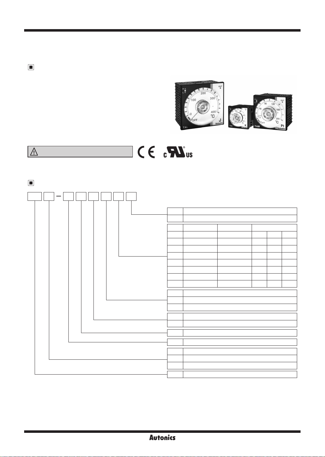
TA Series
Analog And Non-Indicating Type, PID Control,
Set Temperature By Dial
Features
● Improved control performance with built-in
microcomputer
● Adopting new Auto-tuning PID control algorithm
: Selectable ON/OFF, PID control (the external switch)
● Easy to check controlling status with deviation
indicators
: Deviation LED (red, green), output LED (red) indicators
● Dial setting output OFF function
● Sensor broken display function
Please read “Safety Considerations”
in the instruction manual before using.
L..=I
&::...__
____
Ordering Information
___JI
( € c
'i\lus
TA S B 4 R P 4 C
-
T
Temperature range
for each sensor
Sensor input type
Control output
Power supply
Control method
Size
Item
Unit
C Celsius
F Fahrenheit
I I I
0 -50 to 100 -58 to 212 DPt
1 0 to 100 32 to 212 DPt
2 0 to 200 32 to 392 DPt J (IC) K (CA)
3 0 to 300 32 to 572
4 0 to 400 32 to 752 DPt J (IC) K (CA)
6 0 to 600 32 to 1,112
8 0 to 800 32 to 1,472
C 0 to 1,200 32 to 2,192
P DPt100Ω
J J (IC)
K K (CA)
R Relay output
S SSR drive output
4 100-240VAC 50/60Hz
B ON/OFF control & PID control combined
S DIN W48 x H48mm (8-pin plug type)
M DIN W72 x H72mm
L DIN W96 x H96mm
TA Analog setting type temperature controller
℃
℉
℃ ℉
Temperature sensor
- -
-
K (CA)
-
J (IC)
-
- -
- -
- -
※
1
K (CA)
K (CA)
K (CA)
※
1: 8-pin socket (PG-08, PS-08
J-134
) is sold separately.
(N)
Autonics
Analog Setting Non-Indicating Type, PID Control
Specifications
00
Series TAS TAM TAL
Power supply 100-240VACᜠ 50/60Hz
Allowable voltage range 90 to 110% of rated voltage
Power consumption Max. 4VA
Size DIN W48×H48mm DIN W72×H72mm DIN W96×H96mm
Display method Deviation LED (red, green), Output LED (red)
Setting type Dial setting
Setting accuracy
Input
type
Control
Control
output
※
1
F.S. ±2% (room temperature 23℃±5℃)
RTD DPt100Ω (allowable line resistance max. 5Ω per a wire)
Thermocouples K (CA), J (IC)
ON/OFF Control Hysteresis: 2℃ xed
PID Control Control period: Relay output - 20 sec / SSR drive output - 2 sec
Relay 250VACᜠ 3A, 30VDCᜡ 1A, 1c
SSR 12VDCᜡ±2V 20mA Max.
Functions PV deviation indicatable, Error indicatable
Sampling period 100ms
Dielectric strength 2,000VAC 50/60Hz for 1 min (between input terminal and power terminal)
Vibration 0.75mm amplitude at frequency of 5 to 55Hz (for 1 min) in each X, Y
Relay
life cycle
Mechanical Min. 10,000,000 operations (18,000 operations/hr)
I
Electrical Min. 100,000 operations (900 operations/hr)
I
Insulation resistance Min. 100MΩ (at 500VDC megger)
Noise immunity ±2kV R-phase, S-phase the square wave noise (pulse width: 1us) by the noise simulator
Memory retention Approx. 10 years (when using non-volatile semiconductor memory type)
Environment
Insulation type
Approval
Weight
※
Ambient temperature -10 to 50℃, storage: -20 to 60
I
Ambient humidity 35 to 85%RH, storage: 35 to 85%RH
I
※
2
1: <at room temperature range> Below 100
Double insulation or reinforced insulation
[QI
(mark:
, dielectric strength between the measuring input part and the power part: 2kV)
(
E:
c'i\lus
Approx. 107g (approx. 69g) Approx. 171g (approx. 109g) Approx. 232g (approx. 147g)
model is F.S. ±3%
℃
<out of room temperature range> Below 100℃ model is F.S. ±4%, Over 100℃ model is F.S. ±3%
※
2: The weight includes packaging. The weight in parenthesis is for unit only.
※
Environment resistance is rated at no freezing or condensation.
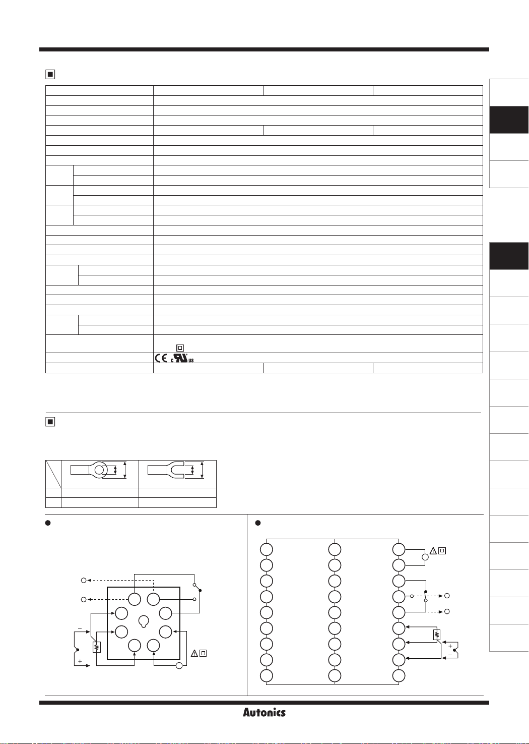
Connections
00
※
RTD: DPt100Ω (3-wire type)
※
Thermocouple: K (CA), J (IC)
※
Use teminals of size specied below.
N.O.
SOURCE:
~
100-240VAC
4VA 50/60Hz
a
COM
b
N.C.
a
b
<Round>
a Min. 3.0mm Min. 3.0mm
b Max. 5 8mm Max. 5 8mm
TAS
• •
※
Socket (PG-08, PS-08 (N)) is sold separately)
(
SSR
12VDC ±2V
20mA Max.
SENSOR
+
-
B'
3 6
B
2 7
A
RTD
TC
<Forked>
RELAY OUT
250VAC 3A 1c
30VDC 1A 1c
RESISTIVE LOAD
5
4
8
1
I I
I I
℃
I I
TAM
1
2
3
4
5
6
7
8
9
19
20
21
22
23
24
25
26
27
, Z direction for 2 hours
RELAY OUT
250VAC 3A 1c
30VDC 1A 1c
RESISTIVE LOAD
10
11
12
N.O.
13
COM
14
A
15
B
16
B'
17
18
~
RTD
N.C.
SOURCE:
100-240VAC
4VA 50/60Hz
SSR
+
12VDC ±2V
20mA Max.
-
TC
SENSOR
SENSORS
CONTROLLERS
MOTION DEVICES
SOFTWARE
(J)
Temperature
Controllers
(K)
SSRs
(L)
Power
Controllers
(M)
Counters
(N)
Timers
(O)
Digital
Panel Meters
(P)
Indicators
(Q)
Converters
(R)
Digital
Display Units
(S)
Sensor
Controllers
(T)
Switching
Mode Power
Supplies
(U)
Recorders
(V)
HMIs
(W)
Panel PC
(X)
Field Network
Devices
Autonics
J-135
 Loading...