

TEMPERATURE CONTROLLER
TAS/TAM/TAL SERIES
M A N U A L
Thank you very much for selecting Autonics products.
For your safety, please read the following before using.
Caution for your safety
Please keep these instructions and review them before using this unit.
※
Please observe the cautions that follow;
※
Warning
Caution
The following is an explanation of the symbols used in the operation manual.
※
Warning
1. In case of using this unit with machinery(Ex: nuclear power control, medical equipment, ship, vehicle,
train, airplane, combustion apparatus, safety device, crime/disaster prevention equipment, etc) which
may cause damages to human life or property, it is required to install fail-safe device.
It may cause a re, human injury or damage to property
2. It must be mounted on Panel.
It may give an electric shock.
3. Do not connect, inspect and repair terminals when it is power on.
It may give an electric shock.
4. Please check the number of terminal when connecting power or input.
It may cause a re.
5. Do not disassemble or modify this unit, please contact us when it is required.
It may cause a re and give an electric shock.
Caution
1. This unit shall not be used outdoors.
It might shorten the life cycle of the product or give an electric shock.
2. When wire connection, AWG 20(0.50mm²) should be used and screw bolt on terminal block with 0.74
to 0.90N·m strength.
It may result in malfunction or re due to contact failure.
3. For crimpled terminal, select following shaped terminal.
4. Please observe specication rating.
It might shorten the life cycle of the product and cause a re.
5. Do not use the load beyond rated switching capacity of Relay contact.
It may cause insulation failure, contact melt, contact failure, relay broken, re etc.
6. In cleaning the unit, do not use water or an oil-based detergent.
It might cause an electric shock or re that will result in damage to the product.
7. Do not use this unit at place where there are ammable or explosive gas, humidity, direct ray of the
sun, radiant heat, vibration, impact etc.
It may cause a re or explosion.
8. Do not inow dust or wire dregs into inside of this unit.
It may cause a re or mechanical trouble.
9. Please wire properly after checking the polarity of terminals when connect thermocouples.
It may cause a re or explosion.
10. In order to install the units with reinforced insulation, use the power supply unit which basic
insulation level is ensured.
Ordering information
TA S B 4 R P 4 C
Item
1: Socket(PG-08, PS-08) is sold separately.
※
The above specifications are subject to change without notice.
※
Serious injury may result if instructions are not followed.
Product may be damaged, or injury may result if instructions are not followed.
Caution: Injury or danger may occur under special conditions.
Max. 5.8mm Max. 5.8mm
Unit
C Celsius(℃)
F Fahrenheit(℉)
Celsius(℃) Fahrenheit(℉)
Temperature
range
for each sensor
0 -50 to 100 -58 to 212 Pt
1 0 to 100 32 to 212 Pt
2 0 to 200 32 to 392 Pt J K
3 0 to 300 32 to 572
4 0 to 400 32 to 752 Pt J K
6 0 to 600 32 to 1,112
8 0 to 800 32 to 1,472
C 0 to 1,200 32 to 2,192
Sensor input type
P DPt100Ω
J J(IC)
K K(CA)
Control output
Power supply
Control method
Size
R Relay output
S SSR drive output
4 100-240VAC 50/60Hz
B ON/OFF control & PID control combined
S DIN W48 x H48mm(8 pin plug type)
M DIN W72 x H72mm
L DIN W72 x H72mm
TA Analog setting type temperature controller
Temperature sensor
- -
-
-
J
- -
- -
- -
1
※
Specication
Series TAS TAM TAL
Power supply 100-240VAC 50/60Hz
Allowable voltage range 90 to 110% of rated voltage
Power consumption Max. 4VA
Size DIN W48 x H48mm DIN W72 x H72mm DIN W96 x H96mm
Display method Deviation LED(red, green), Output LED(red)
Setting type Dial setting
Setting accuracy F.S. ±2% (room temperature 23℃ ±5℃)
RTD DPt 100Ω(allowable line resistance max. 5Ω per a wire)
Input
type
Thermocouples K(CA), J(IC)
ON/OFF Control Hysteresis: 2℃ Fixed
Control
PID Control Control period: Relay output 20 sec./SSR drive output 2 sec.
Relay 250VAC 3A 1c
Control
output
SSR Max. 12VDC±2V 20mA
Functions PV deviation indication, Error indication
Dielectric strength 2,000VAC 50/60Hz for 1minute(between input terminal and power terminal)
Vibration 0.75mm amplitude at frequency of 5 to 55Hz in each of X, Y, Z directions for 2hours
Mechanical Min. 10,000,000 operation(18,000 times/hr)
Relay life
cycle
Electrical Min. 100,000 operation(900 times/hr)
Insulation resistance Min. 100MΩ(at 500VDC megger)
Noise strength Square shaped noise by noise simulator(pulse width 1㎲) ±2kV R-phase and S-phase
Memory retention Approx. 10 years (when using non-volatile semiconductor memory type)
Ambient temperature
Environ
-ment
Ambient humidity 35 to 85%RH, Storage: 35 to 85%RH
Insulation type
Approval
2
※
Weight
1: <Except normal temperature range> Below 100℃ model is F.S. ±4%, Over 100℃ model is F.S. ±3%
※
2: The weight is with packaging and the weight in parentheses is only unit weight.
※
Environment resistance is rated at no freezing or condensation.
※
-10 to 50℃ , Storage: -20 to 60
Double insulation or reinforced insulation
(mark: , dielectric strength between the measuring input part and the power part: 2kV)
Approx. 112g(approx. 74g) Approx. 176g(approx. 114g) Approx. 237g(approx. 152g)
Front panel Identication
1
2
1. Deviation indicator
It shows deviation of present temperature(PV) based on set temperature(SV) by LED.
Input deviation indicator[Deviation indicator:
PV deviation temperature Deviation indicator
Input sensor OPEN ▲ +
Exceed max. input value ▲ indicator ashes(every 0.5 sec.)
More than 10
℃
More than 2℃ to less than or equal to 10℃▲ +
Less than or equal to ±2
℃
More than -2℃ to less than or equal to -10℃
More than -10
℃
Less than min. input value ▼ indicator ashes(every 0.5 sec.)
This is the same as Fahrenheit(℉).
※
When power is on, all indicators light for 2 sec., then all indicators turn off and control
operation starts.
2. Set temperature(SV) dial
Dial to change set temperature (SV). When changing set temperature, it is applied after 2 sec. for the stable
input.
3. Input sensor
Indicates sensor type of present value.
Input sensor type or input range each product is shown in the below table.
Input Sensor Range No. Input range(℃) Input range(℉)
1 0 to 100 32 to 212
2 0 to 200 32 to 392
K
-
K
K
K
K(CA)
Thermocouple
J(IC)
4 0 to 400 32 to 752
6 0 to 600 32 to 1,112
8 0 to 800 32 to 1,472
C 0 to 1,200 32 to 2,192
2 0 to 200 32 to 392
3 0 to 300 32 to 572
4 0 to 400 32 to 752
0 -50 to 100 -58 to 212
RTD DPt100Ω
1 0 to 100 32 to 212
2 0 to 200 32 to 392
4 0 to 400 32 to 752
Set temperature within input range each sensor.
※
4. Temperature unit
Indicates temperature unit(℃, ℉) of set temperature(SV) and present value(PV).
5. Temperature range
Indicates temperature range of set temperature(SV)
6. Control output indicator
Turns ON when control output (Relay Output/SSR Output)
7. Control mode selection switch
Select PID control or ON/OFF control using switch.
8. Terminal block
Terminals for external connections. For more information, refer to '
6
5
4
3
(green), ▲/▼(red)]
+ ▼ indicators ash(every 0.5 sec.)
▲ indicator turns ON
+ ▼ indicators turn ON
▼ indicator turns ON
1
※
℃
7 8
indicators turn ON
indicator turns ON
Connections'.
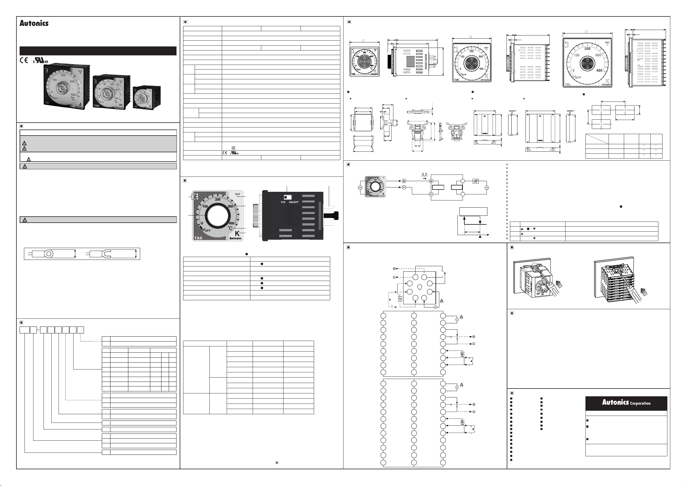
Dimensions
1. TAS Series
48
14
5.2
Bracket
TAS Series TAM, TAL Series
□48.6
45
44.9
55
56
31
20
5
36
16
15
21
66.7
52
46
12
23.9
37.5
3.34
40.5
2. TAM Series
72
44.8
Terminal cover(sold separately)
RMA-COVER(72×72mm)
Functions
1. SSR drive output
SSR drive output
12VDC
Power
Temperature
controller
2. ON/OFF control
ON/OFF control function is for controlling temperature by comparing
present temperature(PV) to set temperature(SV). ON/OFF control is
xed on reverse operation(Heating). Output turns on to supply power
temperature(SV) and the output turns off to turn off heater when present
temperature(PV) is higher then set temperature(SV).
Hysteresis is xed at 2℃ during ON/OFF control.
※
SSR module
INPUT
SRH1 Series
LOAD
Reverse operation
(Heating)
Hysteresis
Control output
Load
Connections
RTD(Platinum resistance thermometer): DPt100Ω(3-wire) ※T.C.(Thermocouple): K(CA), J(IC)
※
1. TAS Series
2. TAM Series
3. TAL Series
SSR
12VDC±2V
20mA Max
T.C.
SENSOR
RTD
1 19 10
2 20 11
3 21 12
4 22 13
5 23 14
6 24 15
7 25 16
8 26 17
9 27 18
1 25 13
2 26 14
3 27 15
4 28 16
5 29 17
6 30 18
7 31 19
8 32 20
9 33 21
10 34 22
11 35 23
12 36 24
B'
B
A
RELAY OUT
250VAC 3A 1c
RESISTIVE LOAD
3
2
148
RELAY OUT
250VAC 3A 1c
RESISTIVE LOAD
RELAY OUT
250VAC 3A 1c
RESISTIVE LOAD
(※Socket(PG-08, PS-08) is sold separately.)
COM
5
N.C.
N.O.
6
7
SOURCE
100-240VAC
4VA 50/60Hz
SOURCE
100-240VAC
4VA 50/60Hz
N.C.
N.O.
B
B'
N.O.
B
B'
COM
RTDA
N.C.
COM
RTDA
T.C.
SENSOR
SOURCE
100-240VAC
4VA 50/60Hz
T.C.
SENSOR
SSR
12VDC±2V
20mA Max
SSR
12VDC±2V
20mA Max
70
Power
SV
Temperature
68.5
13
14.7
6.5
3
64
3. TAL Series
64.5
RLA-COVER(96×96mm )
94
91.5
13
96
Panel cut-out
3
B
86
Size
Series
TAS Min. 65 Min. 65 45 45
TAM Min. 90 Min. 90 68 68
14.7 64.5
6.5
A
D
C
A B C D
TAL Min. 115 Min. 115 92 92
3. PID Control
PID constants are suggested and implemented based on self tuning from supply power until reaching set
temperature(SV), then self tuning is over after reaching set temperature(SV). When power supply, in case that
set temperature(SV) dial points at OFF or self tuning can not be started because present temperature(PV) is
higher than set temperature(SV) or hunting occurs during self tuning, output control is switched to proportion
band(P) because that is considered to error. At that time, proportion band is xed at 10℃.
Control cycle of PID control and proportion control is 20 sec. in relay output model and 2 sec. in SSR drive
※
output model.
4. STOP
Control output could stop without power off by setting the front setting volume to below min. setting range.
If control output stops by STOP function, green indicator in deviation indicator( ) will ash every 1 sec.
5. Error
Error mark will ash(every 1 sec.) in PV indicator when error occurs during the control operation.
It will operate normally, if input sensor is connected or temperature is returned to normal range.
No Display Description
1
+ + indicators ash If input sensor is broken or sensor is not connected.
2
indicator ashes If measured sensor input is higher than temperature range.
3
indicator ashes If measured sensor input is lower than temperature range.
Installation
1. TAS Series
Mount the product on the panel and securely push the bracket in using a tool, as shown in the diagram.
※
2. TAM, TAL Series
Caution for using
1. Please use separated line from high voltage line or power line in order to avoid inductive noise.
2. Install power switch or circuit-breaker in order to on/off the power.
3. The switch or circuit-breaker should be installed nearby users for safety.
4. Do not use this product as Volt-meter or Ampere-meter, this is a temperature controller.
5. In case of using RTD sensor, 3-wire type must be used. If you need to extend the line, 3 wires must be used
with the same thickness as the line. It might cause the deviation of temperature if the resistance of line is
different.
6. In case of making power line and input signal line closely, line lter for noise protection should be installed at
power line and input signal line should be shielded.
7. Keep away from the high frequency instruments. (High frequency welding machine & sewing machine, large
capacity SCR controller)
8. Installation environment
It shall be used indoor.
①
Altitude Max. 2,000m
②
Pollution Degree 2
③
Installation Category
④
It may cause malfunction if above instructions are not followed.
※
Major products
Photoelectric sensors Temperature controllers
Fiber optic sensors Temperature/Humidity transducers
Door sensors SSR/Power controllers
Door side sensors Counters
Area sensors Timers
Proximity sensors Panel meters
Pressure sensors Tachometer/Pulse(Rate) meters
Rotary encoders Display units
Connector/Sockets Sensor controllers
Switching mode power supplies
Control switches/Lamps/Buzzers
I/O Terminal Blocks & Cables
Stepper motors/drivers/motion controllers
Graphic/Logic panels
Field network devices
Laser marking system(Fiber, CO₂, Nd:YAG)
Laser welding/soldering system
Ⅱ
http://www.autonics.com
Satisable Partner For Factory Automation
HEAD QUARTERS:
116, Ungbigongdan-gil, Yangsan-si, Gyeongsangnam-do, Korea
OVERSEAS SALES:
#402-404, Bucheon Techno Park, 655, Pyeongcheon-ro,
Wonmi-gu, Bucheon, Gyeonggi-do, Korea
TEL: 82-32-610-2730 / FAX: 82-32-329-0728
E-mail: sales@autonics.com
The proposal of a product improvement and
development: product@autonics.com
EP-KE-03-0340C
0.6
0.6
0
0
0.7
0.7
0
0
0.8
0.8
0
0
 Loading...