

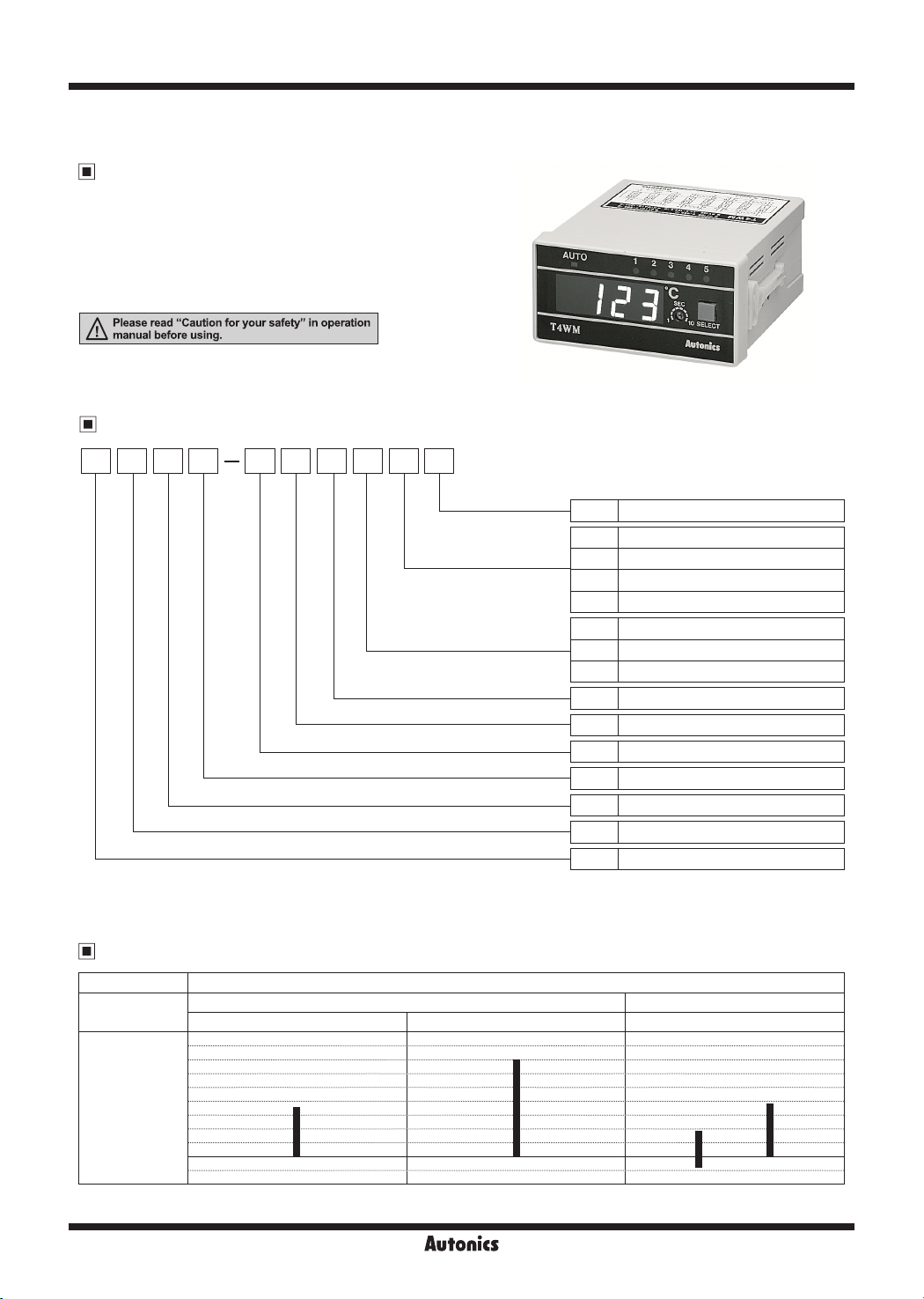
T4WM Series
5-CH Temperature Indicator
Features
● Indication type only
● High accuracy measurement: F.S. ±0.5%
● 5-Point temperature measurement
● Automatic or manual display of temperature in each point
~
f
f'
I.:..
Please read "Caution
ill
manual before using.
for
your
safety" in operation
Ordering Information
T N4 3W NM P 4 C
Digit
Item
※
Please check the range of temperature when select model.
-
Temperature range
Sensor input type
Control output
Power supply
Control method
Input
Size
Unit
9
C
℃
I
I
0 -99.9 to 199.9
4 0 to 399
5 0 to 500
C 0 to 1200
P DPt100Ω
J J(IC)
K K(CA)
I
N No output
I
I
3 110/220VAC 50/60
I
I
N No control
I
I
M 5-Point Indicator
I
I
W DIN W96×H48
I
4 9999 (4-digit)
I
I
T Temperature Controller
I
㎐
mm
I
Temperature Range For Each Sensor
Model T4WM
Thermocouples RTD
H-154
Sensor input
type
(℃)
Standard
scale
range
1600
1200
1000
800
600
400
200
100
-100
J(IC) K(CA) DPt100Ω
500℃ 399℃
■
■
■
0
I
Autonics
1200℃
199.9℃
■
I
-99.9℃
■
5-CH Temperature Indicator
Specications
Series T4WM
Power supply 110/220VAC 50/60Hz
Allowable voltage range 90 to 110% of rated voltage
Power consumption Max. 3VA
Display method 7-segment LED method
Character size (W×H) 9.8×14.2
Display accuracy F.S. ±0.5% rdg ±1-digit
Input sensor Thermocouples: K(CA), J(IC) / RTD: DPt100Ω
Input line resistance Thermocouples: Max. 100Ω / RTD: Allowable line resistance max. 5Ω per a wire
Connectable sensors 5 (thermocouple, RTD are not used as mixed)
Channel switch Selectable Auto/Manual switching
Auto switching time Variable 1 to 10 sec (by built-in adjuster)
Insulation resistance Over 100MΩ (at 500VDC megger)
Dielectric strength 2,000VAC 50/60Hz for 1 min
Noise immunity ±1kV the square wave noise (pulse width: 1㎲) by the noise simulator
Vibration
Shock
Environment
Unit weight Approx. 322g
※
Mechanical 0.75mm amplitude at frequency of 10 to 55Hz (for 1 min) in each X, Y
Malfunction 0.5mm amplitude at frequency of 10 to 55Hz (for 1 min) in each X, Y, Z direction for 10 min
Mechanical 300m/s² (approx. 30G)
Malfunction 100m/s² (approx. 10G) in each X, Y, Z direction for 3 times
Ambient temperature -10 to 50℃, storage:-25 to 65
Ambient humidity 35 to 85%RH
Environment resistance is rated at no freezing or condensation.
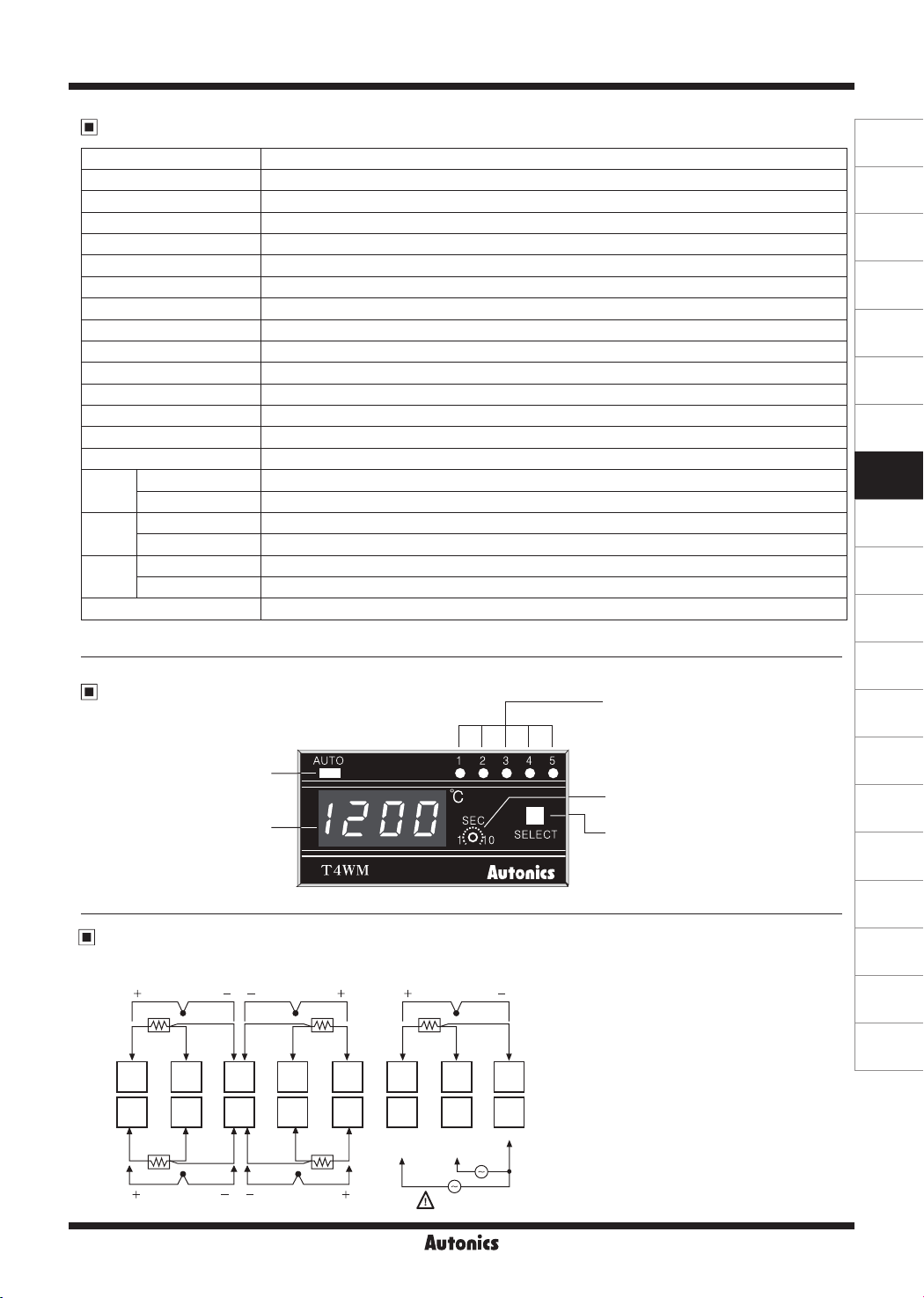
Unit Description
Channel auto switching
(LED ON: Auto switching,
LED OFF: Manual switching)
indicator
Temperature
display
mm
in each X, Y, Z direction for 3 times
℃
I AUTO
--
I ,=i,,,,
-IL
T4WM
LILI
1 2 3 4 5
• • • • •
SEC
{o)o
■-
SELECT
Autonics
, Z direction for 1 hour
Channel indicator
(LED ON display)
Auto switching time adjuster
(1 to 10 sec)
Selection switch
(Auto/Manual channel switching)
Connections
※
RTD: DPt100Ω (3-wire type) ※Thermocouple: K(CA), J(IC)
1 2
+ +
TC
RTD
A
B
B'
9 10 12 13 14 15 1611
1 2 4 5 6 7 83
B
B'
A
4 5
+ +
B'
TC
RTD
AA
ill
220VAC
B
□□□
A
50/60Hz
RTDRTD
TCTC
~
3
+ -
BB
110VAC
50/60Hz
SOURCE
A
TC
RTD
B'B'
0V
(A)
Photoelectric
Sensors
(B)
Fiber
Optic
Sensors
(C)
Door/Area
Sensors
(D)
Proximity
Sensors
(E)
Pressure
Sensors
(F)
Rotary
Encoders
(G)
Connectors/
Connector Cables/
Sensor Distribution
Boxes/Sockets
(H)
Temperature
Controllers
(I)
SSRs / Power
Controllers
(J)
Counters
(K)
Timers
(L)
Panel
Meters
(M)
Tacho /
Speed / Pulse
Meters
(N)
Display
Units
(O)
Sensor
Controllers
(P)
Switching
Mode Power
Supplies
(Q)
Stepper Motors
& Drivers
& Controllers
(R)
Graphic/
Logic
Panels
(S)
Field
Network
Devices
(T)
Software
Autonics
H-155

T4WM Series
Dimensions
98
12 100
48
-AUTO-,
~
-_-_-_t--
1_11111
I
I / L
----
----
T4WM
----
LI LI
96
2 3 4
51
SEC
■
\Oi10
SELECT
1
I
Autonics
Channel Switching
Auto/Manual channel switching
Auto switching
When pressing this for
3 sec and the channel
auto switching indicator
turns ON and channels
switch automatically.
(AUTO LED: ON)
Auto channel switching
The temperature of each channel is displayed during
•
auto switching time and switching to the next channel
automatically.
Auto switching time is variable up to 10 sec by the front
•
adjuster.
When it is auto channel switching, the channel auto
•
switching indicator turns ON.
Select
switch
S LECT
g
Manual swithcing
When press this once,
the channel indicator
turns ON and channels
switch manually
(AUTO LED: OFF)
(unit: mm)
● Panel cut-out
Min. 116
0.6
0
45
0.8
92
45
Min. 52
0
Selection Of Input Sensor Number
By Internal DIP Switch
Max. 5 dierent sensors can be connected but do not use
thermocouple and RTD together.
Sensor
~
DIP
switch
Memory Protection
00
When the power fails, the data value will be protected for 3
months. (The battery must be charged fully.)
2 3 4 5
3 2 1
ON
OFF
~~~ ~~~ ~~~
ON
OFF
3 2 1
ON
OFF
3 2 1
ON
OFF
3 2 1
~~~
Manual channel switching
Whenever touching selection switch (SELECT), channel
switches.
When a channel indicator turns ON, the temperature of the
channel is displayed and whenever touching the switch, it
moves to next channel.
④
Sensor
⑤ ③ ①
H-156
②
Autonics
 Loading...