

Autonics T4WM SERIES Instruction Manual
DRW170790AB
Autonics
5-CH TEMPERATURE INDICATOR
T4WM SERIES
I N S T R U C T I O N M A U A L
Please read the following safety considerations before use.
Safety Considerations
※
Please observe all safety considerations for safe and proper product operation to
avoid hazards.
※
Safety considerations are categorized as follows.
Warning Failure to follow these instructions may result in serious injury or death.
Caution
※
The symbols used on the product and instruction manual represent the following
symbol represents cau ion due to special circumstances in which hazards may occur.
1. Fail-safe device must be installed when using the unit with machinery that may
cause serious injury or substantial economic loss. (e.g. nuclear power control,
medical equipment, ships, vehicles, railways, aircraft, combustion apparatus,
safety equipment, crime/disaster prevention devices, etc.)
Failure to follow this instruction may result in re, personal injury, or economic loss.
2. Install on a device panel to use.
Failure to follow this instruction may result in electric shock or re.
3. Do not connect, repair, or inspect the unit while connected to a power source.
Failure to follow this instruction may result in electric shock or re.
4. Check 'Connections' before wiring.
Failure to follow this instruction may result in re.
5. Do not disassemble or modify the unit.
Failure to follow this instruction may result in electric shock or re.
6. Since Lithium battery is embedded in the product, do not disassemble or burn
the unit.
Failure to follow this instruction may result in re.
1. When connecting the power input and relay output, use AWG 20(0.50mm2)
cable or over and tighten the terminal screw with a tightening torque of 1.0N.m.
When connecting the sensor input and communication cable without dedicated
cable, use AWG 28~16 cable and tighten the terminal screw with a tightening
torque of 1.0N.m.
Failure to follow this instruction may result in re or malfunction due to contact failure.
2. Use the unit within the rated specications.
Failure to follow this instruction may result in re or product damage.
3. Use dry cloth to clean the unit, and do not use water or organic solvent.
Failure to follow this instruction may result in electric shock or re.
4. Do not use the unit in the place where ammable/explosive/corrosive gas,
humidity, direct sunlight, radiant heat, vibration, impact, or salinity may be
present.
Failure to follow this instruction may result in re or explosion.
5. Keep metal chip, dust, and wire residue from owing into the unit.
Failure to follow this instruction may result in re or product damage.
Unit Description
00
Channel auto switching indicator
1.
LED ON: Auto switching, LED OFF: Manual switching
2. Channel indicator (LED ON display)
3. Auto switching time adjuster (1 to 10 sec)
4. Selection switch
Auto/Manual channel switching
5. T
emperature display
The above specications are subject to change and some models may be
※
discontinued without notice.
Be sure to follow cautions written in the instruction manual and the technical
※
descriptions (catalog, homepage).
Thank you for choosing our Autonics product.
Failure to follow these instructions may result in personal injury or product damage.
Warning
Caution
2
I I
AUTO
1
- . . . . .
j
t
_,
5
I L
T4WM
_,
-'
Lt
I
12345
.:..
,o;
0
sec
10
Autonics
■
sELEcr
3
4
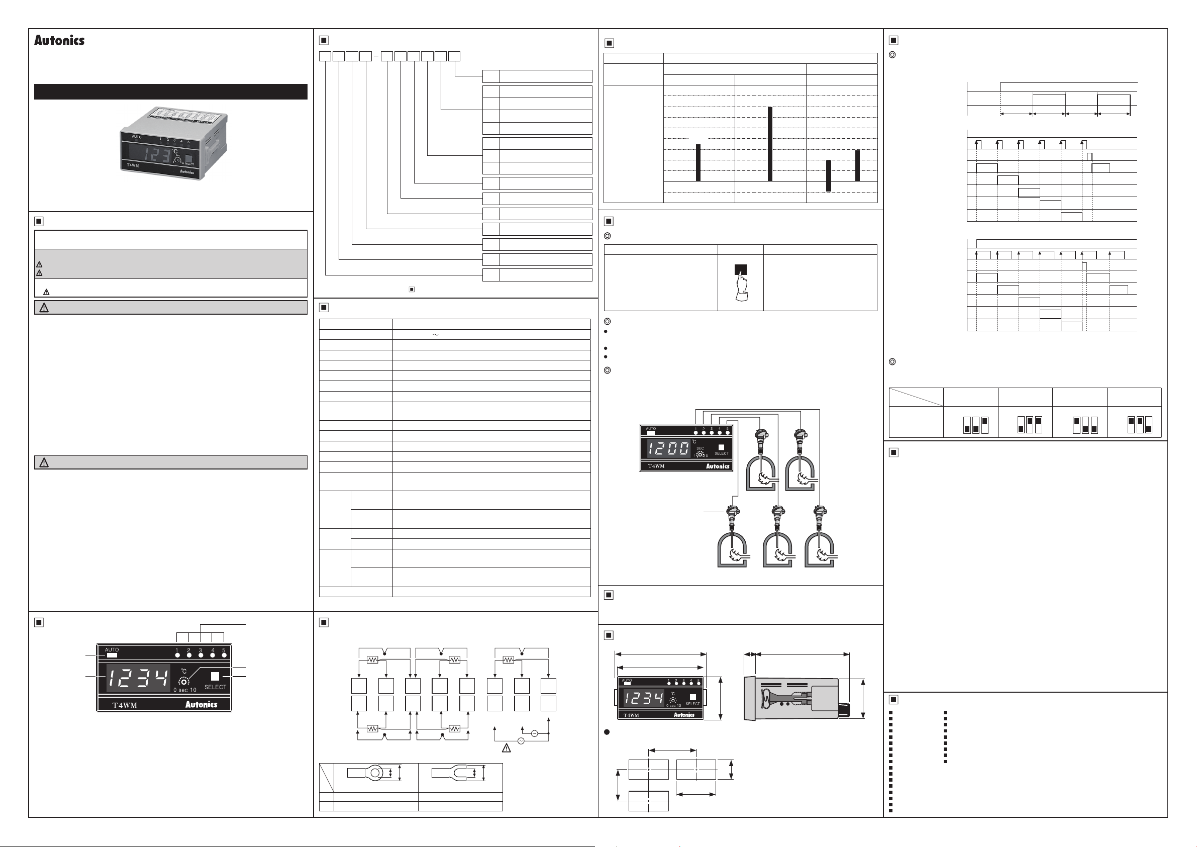
Ordering information 5 Point indicator
T N4 3W NM P 4 C
11111-IIIIIIIL
Unit
C
℃
I
Temperature
range
Sensor input type
Control output
Power supply
Control method
Input
Size
Digit
Item
※
Please check the range of Temperature Range For Each Sensor' when select model.
0 -99.9 to 199.9
4 0 to 399
5 0 to 500
C 0 to 1200
P DPt100Ω
J J(IC)
K K(CA)
N No output
3 110/220VAC 50/60
N No control
M 5-Point Indicator
W DIN W96×H48
4 9999 (4-digit)
T Temperature Controller
㎐
mm
Temperature Range For Each Sensor
Model T4WM
Thermocouple RTD
K(CA) DPt100Ω
1200
℃
500
℃
I
Sensor
input type
Standard
scale
range
(℃)
J(IC)
1600
1200
1000
800
600
400
200
~~~····.···
100
0
-100
Channel Switching
Auto/Manual channel switching
Auto switching Select witch Manual swithcing
When pressing this for 3 sec
and the channel auto switching
indicator turns ON and channels
switch automatically.
(AUTO LED: ON)
SE CT
g
When press this once, the channel
indicator turns ON and channels
switch manually
(AUTO LED: OFF)
199.9
-99.9
399
℃
......
··
....
℃
℃
··1
........
Mode selection
● How to select the auto mode and manual mode
: The select switch is ON for 3sec.
Selection switch
AUTO LED
● Manual selection : Touch he select switch
AUTO LED
Selection switch
·····
● Auto selection : Display value for each sensor is changed automatically.
AUTO LED
Specications
Series T4WM
Power supply 110/220VAC
Allowable voltage range
Power consumption Max. 3VA
Display method 7-segment LED method
Character size (W×H) 9.8×14.2
Display accuracy F.S. ±0.5% rdg ±1-digit
Input sensor Thermocouples: K(CA), J(IC) / RTD: DPt100Ω
Input line resistance
Connectable sensors 5 (thermocouple, RTD are not used as mixed)
Channel switch Selectable Auto/Manual switching
Auto switching time Variable 1 to 10 sec (by built-in adjuster)
Insulation resistance Over 100MΩ (at 500VDC megger)
Dielectric strength 2,000VAC 50/60Hz for 1 min
Noise immunity
Vibration
Shock
Environment
Unit weight Approx. 322g
※
00
※
※
a Min. 3.5mm Min. 3.5mm
b Max. 7.2mm Max. 7.2mm
Mechanical
Malfunction
Mechanical 300m/s² (approx. 30G) in each X, Y, Z direction for 3 times
Malfunction 100m/s² (approx. 10G) in each X, Y, Z direction for 3 times
Ambient
temperature
Ambient
humidity
Environment resistance is rated at no freezing or condensation.
Connection
RTD: DPt100Ω (3-wire type)
Use teminals of size specied below.
+ - +
TC
RTD
A
mmm
9 10 12 13 14 15 1611
□□□□□□□□
1 2 4 5 6 7 83
A
+ +
<Round>
90 to 110% of rated voltage
Thermocouples: Max. 100Ω / RTD: Allowable line resistance
max. 5Ω per a wire
±1kV the square wave noise (pulse width: 1㎲) by the noise
simulator
0.75mm amplitude at frequency of 10 to 55Hz (for 1 min) in
each X, Y, Z direction for 1 hour
0.5mm amplitude at frequency of 10 to 55Hz (for 1 min) in
each X, Y, Z direction for 10 min
-10 to 50℃, storage:-25 to 65
35 to 85%RH
1 - + -
B
B'
B
B'
- -
4 5
a
b
50/60Hz
mm
※
Thermocouple: K(CA), J(IC)
2
B
B'
<Forked>
TC
RTD
A
RTDRTD
TCTC
a
℃
AA
220VAC
□□□
50/60Hz
b
3
BB
110VAC
50/60Hz
~
SOURCE
A
TC
RTD
B'B'
0V
Auto channel switching
The temperature of each channel is displayed during auto switching time and switching
•
to the next channel automatically.
Auto switching time is variable up to 10 sec by the auto switching time adjuster.
•
When it is auto channel switching, he channel auto switching indicator turns ON.
•
Manual channel switching
Whenever touching selection switch (SELECT), channel switches.
When a channel indicator turns ON, the temperature of the channel is
displayed and whenever touching the switch, it moves to next channel.
mm
④
Sensor
⑤ ③ ①
Memory Protection
00
When the power fails, the data value will be protected for 3 months.
(The battery must be charged fully.)
Dimensions
00
12
48
0
0.6
45.5
~
----
1
:=,
:J
f
,_
_f
----
----
T4WM
Panel cut-out
•
52
Min.
98
96
LI
,'.',
f O ~~c• 10 SELECT
Autaniu
Min. 116
■
92
0.8
0
②
(Unit:mm)
100
45
(Note)*Reset : Automatic reset by DIP switch
CK : Automatic time adjustment
*
Selection of input sensor by inner DIP switch
Max. 5 dierent sensors can be connected but cannot use thermocouple and RTD
together.
Sensor
Switching
SW
Cautions during Use
00
1. Follow instructions in 'Cautions during Use'. Otherwise, It may cause unexpected
accidents.
2. Check the polarity of the terminals before wiring the temperature sensor.
For RTD temperature sensor, wire it as 3-wire type, using cables in same thickness
and length.
For thermocouple (TC) temperature sensor, use the designated compensation wire
for extending wire.
3. Keep away from high voltage lines or power lines to prevent inductive noise.
In case installing power line and input signal line closely, use line lter or varistor at
power line and shielded wire at input signal line.
Do not use near the equipment which generates strong magnetic force or high
frequency noise.
4. Install a power switch or circuit breaker in the easily accessible place for supplying or
disconnecting the power.
5. Do not use the unit for other purpose (e.g. voltmeter, ammeter), but temperature
controller.
6. Make a required space around the unit for radiation of heat.
For accurate temperature measurement, warm up the unit over 20 min after turning
on the power.
7. Make sure that power supply voltage reaches to the rated voltage wi hin 2 sec after
supplying power.
8. Do not wire to terminals which are not used.
9. This unit may be used in the following environments.
Indoors (in the environment condition rated in 'Specications')
①
Altitude max. 2,000m
②
Pollution degree 2
③
Installation category II
④
Main products
00
Photoelectric Sensors Temperature Controllers
Fiber Optic Sensors Temperature/Humidity Transducers
Door Sensors SSRs/Power Controllers
Door Side Sensors Counters
Area Sensors Timers
Proximity Sensors Panel Meters
Pressure Sensors Tachometer/Pulse (Rate) Meters
Rotary Encoders Display Units
Connector/Sockets Sensor Controllers
Switching Mode Power Supplies
Control Switches/Lamps/Buzzers
I/O Terminal Blocks & Cables
Stepper Motors/Drivers/Motion Controllers
Graphic/Logic Panels
Field Network Devices
Laser Marking System (Fiber, Co₂, Nd: YAG)
Laser Welding/Cutting System
ON
OFF
3sec
Reset
*
LED 1
LED 2
LED 3
LED 4
LED 5
*
Reset
*
LED 1
LED 2
LED 3
LED 4
LED 5
2 3 4 5
OFF
■
■
■
■
■
■
■
■
■
ON
CK
3 2 1
ON
ON
ON
ON
ON
OFF
.I.
ON
ON
3 2 1
ON
3sec
OFF
ON
ON
ON
.I.
ON
ON
ON
OFF
OFF
3sec
3 2 1
.I.
ON
ON
ON
3sec
.I
ON
3 2 1
ON
OFF
DRW170790AB
 Loading...