

DRW1707 82 AA
Autonics
THUMBWHEEL SWITCH SETTING TYPE
TEMPERATURE CONTROLLER
T3/T4 SERIES
I N S T R U C T I O N M A N U A L
Thank you for choosing our Autonics product.
Please read the following safety considerations before use.
Safety Considerations
Please observe all safety considerations for safe and proper product operation to avoid hazards.
※
Safety considerations are categorized as follows.
※
Warning Failure to follow these instructions may result in serious injury or death.
Caution
※
1. Fail-safe device must be installed when using the unit with machinery that may cause
2. Install on a device panel to use.
3. Do not connect, repair, or inspect the unit while connected to a power source.
4. Check 'Connections' before wiring.
5. Do not disassemble or modify the unit.
1. When connecting the power input and relay output, use AWG 20(0.50mm2) cable or over
2. Use the unit within the rated specications.
3. Use dry cloth to clean the unit, and do not use water or organic solvent.
4. Do not use the unit in the place where ammable/explosive/corrosive gas, humidity,
5. Keep metal chip, dust, and wire residue from owing into the unit.
l
※
※
Failure to follow these instructions may result in personal injury or product damage.
The symbols used on the product and instruction manual represent the following
symbol represents caution due to special circumstances in which hazards may occur.
Warning
serious injury or substantial economic loss. (e.g. nuclear power control, medical
equipment, ships, vehicles, railways, aircraft, combustion apparatus, safety equipment,
crime/disaster prevention devices, etc.)
Failure to follow this instruction may result in re, personal injury, or economic loss.
Failure to follow this instruction may result in electric shock or re.
Failure to follow this instruction may result in electric shock or re.
Failure to follow this instruction may result in re.
Failure to follow this instruction may result in electric shock or re.
Caution
and tighten the terminal screw with a tightening torque of 1.0N.m.
When connecting the sensor input and communication cable without dedicated cable,
AWG 28~16 cable and tighten the terminal screw with a tightening torque of 1.0N.m.
use
Failure to follow this instruction may result in re or malfunction due to contact failure.
Failure to follow this instruction may result in re or product damage.
Failure to follow this instruction may result in electric shock or re.
direct sunlight, radiant heat, vibration, impact, or salinity may be present.
Failure to follow this instruction may result in re or explosion.
Failure to follow this instruction may result in re or product damage.
Ordering Information
3T S B N4 R P 4 C
Jl Jl
Item
The above specications are subject to change and some models may be discontinued
without notice.
Be sure to follow cautions written in the instruction manual and the technical descriptions
(catalog, homepage).
-I
Control output
Power supply
Control method
Alarm/Sub output
Size
Digit
-
JI
Unit
Temperature range
※
3
Input type
※
※
2
Upgrade
2
N New type
I I
C
℃
F
℉
I I I
0 -99 to 199℃, -99.9 to 199 9
1 0 to 99 9
2 0 to 200℃, 0 to 200.0
※
3
4 0 to 400
8 0 to 800℃/
A 0 to 999
C 0 to 1200
F 600 to 1600
P DPt100Ω
J J (IC)
K K (CA)
R R (PR)
R Relay output
S SSR drive output
C Current output
4 100-240VAC 50/60Hz
B ON/OFF control, Proportional control
No mark
A Alarm output
S Sub output
P Dual setting output
S
M
H
L
3 999 (3 digit)
4 9999 (4 digit)
T Temperature Controller
℃
℃
℉
℃
℃
℃
None
DIN W48×H48mm (8-pin plug type)
DIN W72×H72mm
DIN W48×H96mm
DIN W96×H96mm
J J
℃
℃
Specications
~
Series T3S T3H T3HA T3HS T4M T4MA T4L T4LA T4LP
Power supply 100-240VACᜠ 50/60Hz
Allowable voltage
range
Power consumption Max. 5VA
Display method 7 segment (red) LED method
Character size (W×H)
Input type
Display
※
accuracy
Control
output
Alarm/Sub/
Dual setting output
Control method ON/OFF, Proportional control
Hysteresis F.S. 0.5% F.S. 0.2 to 3% variable
Proportional band F.S. 3% F.S. 1 to 10% variable
Proportional cycle 20 sec.
RESET range F.S. -3 to 3% variable
Relay
life cycle
Dielectric strength 2,000VAC 50/60Hz 1min. (between input terminal and power terminal)
Vibration
Insulation resistance
Noise
Memory retention Approx. 10 years (when using non-volatile semiconductor memory type)
Environ-
ment
※
3
Weight
※
1: In case of the T3S Series and the decimal point display models
At room temperature (23ºC±5ºC): (PV ±0 5% or ±2℃, select the higher one)±1 digit
Out of room temperature range: (PV ±0.5% or ±3℃, select the higher one)±1 digit
※
2: Dual setting output of the T4LP is xed as relay output and it is available as alarm output.
※
3: The weight is with packaging and the weight in parentheses is only unit weight.
※
Environment resistance is rated at no freezing or condensation.
90 to 110% of rated voltage
3.8×7.6mm
RTD DPt100Ω (Allowable line resistance max.5Ω per a wire)
TC K (CA), J (IC) K (CA), J (IC), R (PR)
RTD
●
-
1
●
TC
Relay OUT1: 250VACᜠ 5A 1c, OUT2: 250VACᜠ 2A 1c
SSR Max. 12VDCᜡ±2V 20mA
Current DC4-20mA (resistive load max. 500Ω)
-
Mechanical
Over 5,000,000 times
Electrical OUT1: Over 100,000 times, OUT2: Over 200,000 times
0.75mm amplitude at frequency of 10 to 55Hz (for 1 min.) in each X, Y
direction for 2 hours
Min. 100MΩ (at 500VDC megger)
Square-wave noise by noise simulator (pulse width 1㎲) ±2kV R-phase and S-phase
Ambient
-10 to 50℃, Storage: -20 to 60
temperature
Ambient
35 to 85% RH, Storage: 35 to 85% RH
humidity
Approx. 135g
(approx. 95g)
I
I
I I
6.0×10.0mm 8 0×14 2mm
I
I
I
I
I
At room temperature (23ºC ± 5ºC): (PV ± 0.5% or ±1ºC, select the higher one) ± 1 digit
Out of room temperature range: (PV± 0.5% or ±2ºC, select the higher one)± 1 digit
250VACᜠ 2A 1c
I
-
I I
※
250VAC
2A 1a
2
ᜠ
-
I
l
I
℃
Approx. 239g
(approx. 176g)
l
Approx. 246g
(approx. 180g)
I
Approx. 310g
(approx. 222g)
l
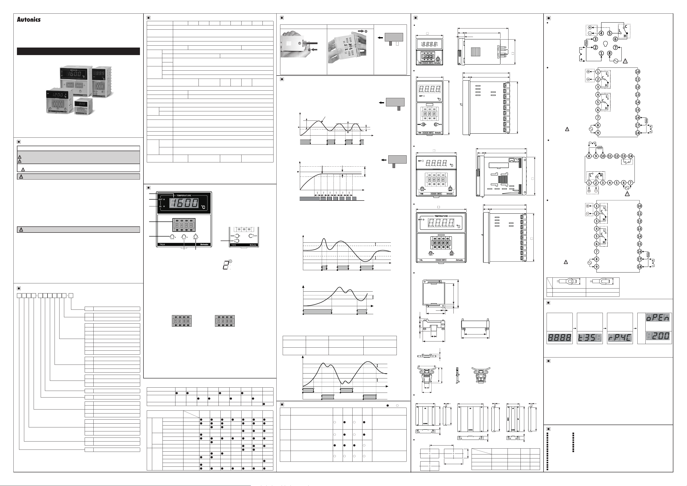
Unit Description
1
2
3
4
11
I I
5
-----!rt-------;,Q,.
1. Present temperature (PV) display
It displays present temperature.
2. Control output (OUT) indicator
It turns ON when control output is ON.
※
In case of the T3S, the upper DOT of last digit ashes.
3. Alarm output (AL) indicator
It turns ON when alarm output is ON. (only for alarm output model)
In case of the sub output model (T3HS), the sub (SUB) indicator turns ON when sub output is ON.
4. Set value (SV) thumbwheel switch
Switch for setting temperature.
(-) button: Decreases number, (+) button: Increases number
If the setting is out of the temperature range of temperature sensor, the present temperature (PV)
display part ashes
※
The models which temperature range is 0 (-99.9 to 199 9℃, -99 to 199℃) of temperature sensor
DPt100Ω are only set 1↔0↔ (-).
※
The dual setting output model (T4LP) has two thumbwheel switches.
LO SET
(low set output)
LO SET (low set output): heating control, HI SET (high set output): cooling control
5. Hysteresis/Proportional width volume switch (except T3S)
ON/OFF control: Setting for hysteresis. [Setting range] F.S. 0 2 to 3% (For T3S, F.S. 0.5% xed)
Proportional control: Setting for proportional width.
Proportional cycle: 20 sec. xed
6. Alarm output value volume switch (only for alarm output model)
It sets alarm output value. [Setting range] F.S. 0 to 10%
7. RESET volume switch
In case of proportional control, it sets offset. [Setting range] F.S. -3 to 3%
8. Temperature setting of sub output volume switch (only for T3HS)
It sets temperature of the sub output. This output operates as deviation low-limit alarm based on
the set sub-output temperature (SV). [Setting range] 0 to 50
※
1: Socket (PG-08, PS-08(N)) is sold separately.
※
2: Output by Series
I
Series T3S T3H
Control output
Control+
Alarm/Sub output
Dual setting output
I r r
※
3: Input type and temperature range by Series
Input type
※
1
T
C
R
T
D
0 to 400
0 to 800
K (CA)
0 to 999
0 to 1200℃C
0 to 200
J (IC)
0 to 400
0 to 800
R (PR) 600 to 1600℃F
-99.9 to 199.9℃0
-99 to 199℃0
0 to 99.9
DPt
100Ω
0 to 200 0℃2
0 to 200
0 to 400
,Q..
-0•
76
and the present value in turn.
SvER
HI SET
(high set output)
[Setting range] F.S. 1 to 10% (For T3S, F.S. 3% xed)
T3HA T3HS
- - - - -
- - - - -
- - - - - - - -
℃
℃
℃
℃
℃
℉
℃
℃
℃
Model
4
8
A
2
4
8
1
2
4
I·
Series
T3S T3H T3HA T3HS
• • • • • • •
•
- - - - -
- - - -
•
•
- - - - - -
- - - -
- - - - -
- - - - -
• •
- - - - - -
: . . . . . .
8
~
[i]~~~
~
T4M
~
r
• • • • •
• •
- - - - - -
• •
8
~ ~
~
~ ~
.±.
℃
T4MA
T4L T4LA
1·
~
T4M
T4MA
-
• • •
• • •
•
•
• • •
• •
- - - - -
- - - - - -
• •
Control Method (ON/OFF, proportional control) Setting
I I
250VACᜠ 2A
1c
I
, Z
11
Before supplying power, remove the case and set the control method by the control method setting switch.
T3S Other Series Control method setting
Press the 8-pin plug with your
thumb. Insert a at head driver to the
groove and uplift the case (same
①
as the other side). Push it to the
direction and the case is removed.
Function
1. Control method
1)ON/OFF control
Comparing the present measured temperature and the set temperature,
the temperature controller turns ON/OFF of the load power. Interval
between ON and OFF of control output is set by the set hysteresis.
When hysteresis of control output is too narrow, hunting (overshoot,
chattering) may occur by external noise.
[Setting range of Hysteresis] F.S. 0.2 to 3%
Set temperature
2)Proportional control
Proportional control has control output which is proportional to
deviation from the present temperature to the set temperature in the
proportional band to the set temperature.
Set temperature
It is available to control without overshoot or hunting comparing ON/OFF control but it may
cause offset. Correct the offset with the RESET volume switch.
[Setting range of Proportional band] F.S. 1 to 10% (In case of T3S, F.S. 3% xed)
[Setting range of RESET] F.S. -3 to 3%
2. Alarm output
Alarm temperature is applied to the high/low-limit based on the set temperature. Alarm output
operates deviation high/low-limit.
[Setting range of Alarm temperature] F.S. 0 to 10%
E.g.) When F.S. is 400
.
3. Sub output (Only for T3HS)
Only the T3HS model has sub output. This output operates as deviation low-limit alarm.
[Setting range of Sub output] 0 to 50
E.g.)Set temperature is set as 100℃ and sub-output is set as 20
4. Dual setting output (Only for T4LP)
Only the T4LP model has dual setting output.
-LO SET (low set output): ON/OFF control (Hysteresis: F.S. 0.2 to 3%),
-HI SET (high set output): Absolute value high-limit alarm output (Hysteresis: 2℃ xed)
E.g.)T4LP, temperature sensor: DPt100, temperature range: 0 to 400
Type Set temperature Output Hysteresis
LO SET
(low set output)
HI SET
(high set output)
T4LP
~
l
T4L
T4LP
T4LA
•
(low set output)
(high set output)
Error Display And Output Operation
I
~
Display Description
OPEN
HHHH
LLLL
SvER
※
1: T4LP (Dual setting output) is the single output.
※
2: When
switch
Front
P
P: Proportional control
(default)
Press the ① with your thumb. Pull
the case to the ② direction and it is
②
removed.
Temperature
Output
Temperature
Output
Sub output
in turn and all output turns OFF.
Overshoot
(SV)
·~-/-\1-(.\--t--
ON
[7
OFF
(SV)
ON
OFF
When the set temperature is set as 100℃, alarm output operation range is 140℃ to 60℃.
Temperature
140℃
138℃
100℃
62℃
60℃
ON
Alarm
OFF
output
Temperature
100℃
82℃
80℃
ON
OFF
Temperature
120℃
118℃
100℃
80℃
78℃
ON
LO SET
OFF
ON
HI SET
OFF
Flashes when a temperature
sensor is broken or not
connected.
Flashes when the measured
input value is higher than the
temperature range of the sensor.
Flashes when the measured
input value is lower than the
temperature range of the sensor.
Flashes with the present value
when the set value is out of the
※
2
temperature range of the sensor.
and
SvER
(In case of T3S, F.S. 0 5% xed)
Measured temperature
(PV)
C1Cl
Measured temperature
(PV)
TTTTT,T
1bb
and max. alarm temperature (F.S. 10%) is 40℃.
℃
Proportional control (Proportional band: F.S. 1 to 10%)
80
℃
120
℃
Hunting width
Offset
□□□□
℃
ON/OFF control
Absolute value high-limit
alarm output
Control
Alarm
Sub
※
1
output
output
output
0
0
•
•
0
0
□·
• • •
0 0 0 0
OPEN/ HHHH/LLLL
occur at the same time,
F: ON/OFF control
※
Front
Hysteresis
Time
※
Front
Proportional
band
Time
※
T: Proportional band is
xed as 20 sec.
Hysteresis 2
Hysteresis 2℃ xed
℃
Hysteresis 2℃ xed
Time
℃
0.5%
(400×0 5%=2℃)
2℃ (xed)
Hysteresis 0.5% (2℃)
Dual
Troubleshooting
output
Check the status of the
temperature sensor. When
the sensor is connected
•
correctly, it is clear.
When the measured
•
temperautre is within the
temperature range of the
sensor, it is clear.
0
The set value should be
within the temperature
range of the sensor.
and
SvER
OPEN/ HHHH/LLLL
Control method
setting switch
P
Control method
setting switch
P F
℃
Hysteresis 2℃ xed
Time
( : ON, : OFF)
• 0
xed
Time
F
F
ash
Dimensions
T3S Series
48
12.3
10 5
90.1
63.8
■
T3H Series
48
1------~
96
Tift
K(CA)(o-400'0)
il!OMfte
※T3HA, a
larm output model, has the alarm output value volume switch.
※
T3HS, sub output model, has the temperature setting of sub output volume switch.
T4M Series
<NrO
72
□
BB.BB
'©
13
11.8
83
70
I
c::::=J
89.3
75
=
c::::=J
mml
c::;J
c::;J
c::::i
c::::i
~
※T4MA,a
T4L Series
larm output model, has the alarm output value volume switch.
96
□
l!!,,-a
12.5
82 5
70
-
=
=
= =
= =
.
※T4LA,a
larm output model, has the alarm output value volume switch.
※
T4LP, dual setting output model, has the two thumbwheel switches.
Bracket
●
T3S Series
0
61
45.4
4.2
4.5
15
7.4
●
T3H/T4M/T4L Series
41
12.2
w
48
3.9
CJ
r.
3 34
~
47.8
61
~
~
46
37.5
40.5
12
23.9
ITI
.
Terminal cover (sold separately)
●
RMA-COVER (72×72mm)● RLA-COVER (96×96mm)
70
68 5
mIIJITT
~
Panel cut-out
13
A
gFTI.11---
i T
3
64
94
[Il]
l!Di
C
I ntj
Series
D
T3S Min. 65 Min. 65 45
T3H Min. 65 Min. 115 45
T4M Min. 90 Min. 90 68
T4L Min. 115 Min. 115 92
●
RHA-COVER (48×96mm)
3
86
91 5
!.
13
Size
l l[l
~
A B C D
(unit: mm)
45
□
91.5
~11°
I
□
=
II
0
;:::
=
=
-
91.5
□
-
;:::
=
=
=
47.2
91 5
13
0 6
45
0
0 6
92
0
0 7
68
0
0 8
92
0
I
Connection
00
T3S
•
SSR OUT 12VDC±2V
20mA Max.
CURRENT OUT DC4-20mA
Load 500Ω Max.
SENSOR
T3H/T3HA/T3HS
•
SSR OUT 12VDC±2V
20mA Max.
CURRENT OUT DC4-20mA
Load 500Ω Max.
SOURCE
100-240VAC
50/60Hz 5VA
T4M/T4MA
•
'
67.5
SSR OUT 12VDC±2V
20mA Max.
CURRENT OUT DC4-20mA
Load 500Ω Max.
T4L/T4LA/T4LP
•
SSR OUT 12VDC±2V
20mA Max.
CURRENT OUT DC4-20mA
Load 500Ω Max.
SOURCE
100-240VAC
50/60Hz 5VA
※
Use teminals of size specied below.
a Min. 3.5mm Min. 3.5mm
b Max. 7.2mm Max. 7.2mm
<Round>
·········~
TC RTD
SENSOR
B' B A
RELAY OUT
250VAC 5A 1c
RESISTIVE LOAD
r-
~-
l
.-:
a
b
A
B'
B
TC
RTD
_ j
<Forked>
RELAY OUT
250VAC 5A 1c
RESISTIVE
LOAD
T3HA
ALARM OUT
250VAC 2A 1c
T3HS
SUB OUT
250VAC 2A 1c
T4MA
ALARM OUT
250VAC 2A 1a
RELAY OUT
250VAC 5A 1c
RESISTIVE
LOAD
T4LA
ALARM OUT
250VAC 2A 1c
T4LP
HI SET OUT
250VAC 2A 1c
a
b
RELAY OUT 250VAC 5A 1c
RESISTIVE LOAD
SOURCE
100-240VAC
50/60Hz 5VA
SOURCE
100-240VAC
50/60Hz 5VA
Display When Power Is ON
When power is supplied, whole display parts turn ON for 1 sec. t displays model type (digits, size,
alarm/sub output and control output, sensor, temp. range, unit). Afterward, it returns to RUN mode.
Displays
Whole parts turn ON
→
When input sensor break/sensor is not connected, it displays [
displays the present input temperature and controls temperature.
During displaying model type, control output does not operate.
※
Cautions during Use
~
1. Follow instructions in 'Cautions during Use'. Otherwise, t may cause unexpected accidents.
2. Check the polarity of the terminals before wiring the temperature sensor.
For RTD temperature sensor, wire it as 3-wire type, using cables in same thickness and length.
For thermocouple (CT) temperature sensor, use the designated compensation wire for extending wire.
3. Keep away from high voltage lines or power lines to prevent inductive noise.
In case installing power line and input signal line closely, use line lter or varistor at power line and
shielded wire at input signal line.
Do not use near the equipment which generates strong magnetic force or high frequency noise.
4. Install a power switch or circuit breaker in the easily accessible place for supplying or disconnecting the power.
5. Do not use the unit for other purpose (e.g. voltmeter, ammeter), but temperature controller.
6. Make a required space around the unit for radiation of heat.
4
86
0 6
0
0 8
0
0 7
0
0 8
0
For accurate temperature measurement, warm up the unit over 20 min after turning on the power.
7. Install a surge absorber at each end of inductive load coil when controlling high-capacity power relay or
inductive load (e.g. magnet).
8. Make sure that power supply voltage reaches to the rated voltage within 2 sec after supplying power.
9. Do not wire to terminals which are not used.
10. This unit may be used in the following environments.
Indoors (in the environment condition rated in 'Specications')
①
Pollution degree 2
③
Major Products
~
Photoelectric Sensors Temperature Controllers
■
Fiber Optic Sensors Temperature/Humidity Transducers
■
Door Sensors SSRs/Power Controllers
■
Door Side Sensors Counters
■
Area Sensors Timers
■
Proximity Sensors Panel Meters
■
Pressure Sensors Tachometer/Pulse (Rate) Meters
■
Rotary Encoders Display Units
■
Connector/Sockets Sensor Controllers
■
Switching Mode Power Supplies
■
Control Switches/Lamps/Buzzers
■
I/O Terminal Blocks & Cables
■
Stepper Motors/Drivers/Motion Controllers
■
Graphic/Logic Panels
■
Field Network Devices
■
Laser Marking System (Fiber, Co₂, Nd: YAG)
■
Laser Welding/Cutting System
■
■
■
■
■
■
■
■
■
■
digits,
size, alarm/sub
output
Displays control
output, sensor,
temp. range, unit
→
RUN
→
mode
OPEN
]. In case of normal operation, it
Altitude max. 2,000m
②
Installation category II
④
A
B
SENSOR
B'
TCRTD
A
B
SENSOR
B'
TCRTD
When input sensor
break/sensor is not
connected
Normal operation
DRW170782A A
 Loading...