

T3 / T4 Series
Temperature Indicator
Features
Various size as DIN specications
•
(W48×H24, W72×H36, W96×H48, W48×H48,
W48×H96, W72×H72, W96×H96mm)
Please read “Safety Considerations” in operation
manual before using.
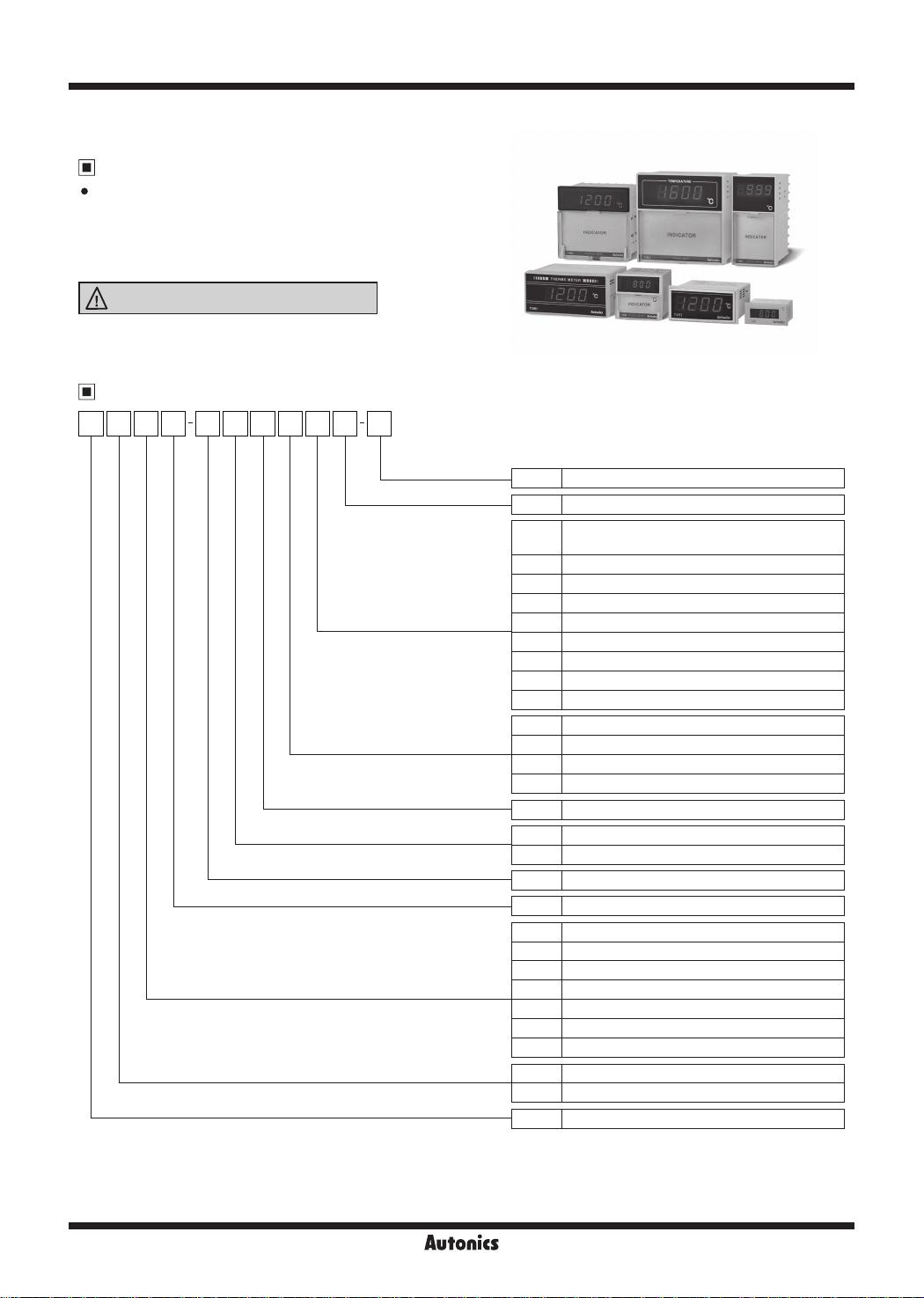
Ordering Information
3T S I N N4 N P 4 C
Digit
Item
-
Alarm/Sub output
Size
II
Control output
Power supply
Control method
II
Input type
※
New
Temperature unit
T
Temperature range
※
3
1
※
3
I
N New type
C
I I I
I
I
℃
-99.9 to 99.9, -99 to 199℃,
0
-99.9 to 199.9
1 0 to 99 9
2 0 to 200
4 0 to 400
5 0 to 500
8 0 to 800
A 0 to 999
C 0 to 1200
F 600 to 1600
P DPt100Ω
J J(IC)
K K(CA)
R R(PR)
N Indicator
X 12-24VDC
4 100-240VAC 50/60Hz
N Indicator
I Indicator
DIN W48×H24mm
N
Y
DIN W72×H36mm
W
DIN W96×H48mm
S
DIN W48×H48mm (8-pin plug type)
H
DIN W48×H96mm
M
DIN W72×H72mm
L
DIN W96×H96mm
3 999 (3-digit)
4 9999 (4-digit)
T Temperature Controller
℃
℃
℃
℃
℃
℃
℃
℃
℃
※
2
I
※
1: Name plate and connections are different from previous T3/T4 Series.
※
2: Sockets (PG-08, PS-08(N)) are sold separately.
H-116
Autonics
Temperature Indicator
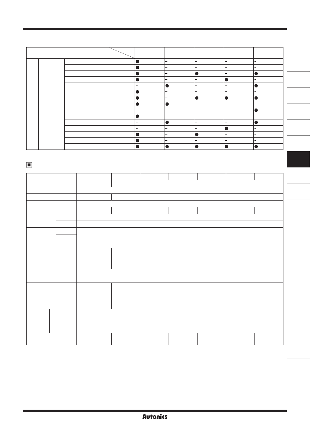
※
3: Input type and temperature range by Series
Series
Input type
0 to 200
℃
0 to 400
℃
K(CA)
J(IC)
Thermocouples
R(PR) 600 to 1600
DPt
RTD
100Ω
※
Please contact us for temperature unit ℉ model.
0 to 800
℃
0 to 999
℃
0 to 1200
℃
0 to 200
℃
0 to 400
℃
0 to 500
℃
-99.9 to 99.9
-99.9 to 199.9
-99 to 199
0 to 99.9
0 to 200
0 to 400
℃
℃
℃
℃
℃
℃
℃
Model
~
2
4
8
A
C
2
4
5
F
0
0
0
1
2
4
T3NI
•
•
•
•
-
•
•
• •
-
•
-
- - -
•
•
• • • • •
Specifications
Series T3NI T4YI T4WI T3SI T3HI T4MI T4LI
Power supply 12-24VDC
Allowable voltage range 90 to 110% of rated voltage
Power consumption Max. 1W Max. 3VA
Display method 7-segment (red) LED method
Character size (W×H) 3.8×7.6mm 8.0×14.2mm 3.8×7.6mm 6.0×10.0mm 8.0×14.2mm
Input type
Display
accuracy
Sampling period
Dielectric strength
V bration 0.75mm amplitude at frequency of 10 to 55Hz (for 1 min) in each X, Y, Z direction for 2 hours
Insulation resistance Over 100MΩ (at 500VDC megger)
Noise immunity
Environment
Weight
※
1: In case of the T3NI, T3SI Series and the decimal point display models
At room temperature (23ºC±5ºC): (PV ±0.5% or ±2℃, select the higher one)±1-digit
Out of room temperature range: (PV ±0.5% or ±3℃, select the higher one)±1-digit
※
2: The weight includes packaging. The weight in parenthesis is for unit only.
※
Environment resistance is rated at no freezing or condensation.
RTD DPt100Ω (allowable line resistance max. 5Ω per a wire)
TC K(CA), J(IC) K(CA), J(IC), R(PR)
※
2
※
1
Ambient
temp.
Ambient
humi.
RTD
TC
At room temperature (23ºC ± 5ºC): (PV ± 0.5% or ±1ºC, select the higher one)±1-digit
●
Out of room temperature range: (PV± 0.5% or ±2ºC, select the higher one)±1-digit
●
100ms
1,000VAC 50/60Hz
for 1 min (between
input terminal and
power terminal)
Square-wave noise
by noise simulator
(pulse width 1㎲)
±500V R-phase and
S-phase
-10 to 50℃, storage: -20 to 60
35 to 85% RH, storage: 35 to 85% RH
Approx. 48g
(approx. 25g)
100-240VACᜠ 50/60Hz
ᜡ
2,000VAC 50/60Hz for 1 min
(between input terminal and power terminal)
Square-wave noise by noise simulator (pulse width 1㎲) ±2kV R-phase and S-phase
Approx. 181g
(approx. 123g)
I I I I I
℃
Approx. 231g
(approx. 140g)
I I I I I
T4YI,
T4WI
T3SI T3HI
- - - -
- - - -
-
- -
•
- - - -
-
•
- -
• • •
- - -
-
•
- - -
- - - -
•
-
- - - -
- -
•
•
- -
I I I
I
Approx. 120g
(approx. 80g)
Approx. 203g
(approx. 137g)
Approx. 202g
(approx. 137g)
T4MI,
T4LI
•
-
•
•
•
-
Approx. 274g
(approx. 185g)
(A)
Photoelectric
Sensors
(B)
Fiber
Optic
Sensors
(C)
Door/Area
Sensors
(D)
Proximity
Sensors
(E)
Pressure
Sensors
(F)
Rotary
Encoders
(G)
Connectors/
Connector Cables/
Sensor Distribution
Boxes/Sockets
(H)
Temperature
Controllers
(I)
SSRs / Power
Controllers
(J)
Counters
(K)
Timers
(L)
Panel
Meters
(M)
Tacho /
Speed / Pulse
Meters
(N)
Display
Units
(O)
Sensor
Controllers
(P)
Switching
Mode Power
Supplies
(Q)
Stepper Motors
& Drivers
& Controllers
(R)
Graphic/
Logic
Panels
(S)
Field
Network
Devices
(T)
Software
Autonics
H-117

T3 / T4 Series
Connections
※
Use teminals of size specied below.
a
b
<Round>
a Min. 3.5mm Min. 3.5mm
b Max. 7.2mm Max. 7.2mm
T3NI
•
3 2 14
□□□□
B'
kJLW
w
SENSOR
0 ® @ ® ® 0
B'B
T4WI
•
1
SOURCE
12-24VDC 1W
ICD
A
t:1
W A
SENSOR
T3SI
•
A
B'
j
RTD
TC
<Forked>
B A
RTD
TC
a
b
1
®I
l@.J
SOURCE
100-240VAC
50/60Hz 3VA
•
T4MI
•
T4YI
B'BA
RTD
TC
SENSOR
SENSOR
TC
B' B A
RTD
SOURCE
100-240VAC
50/60Hz 3VA
SENSOR
T3HI, T4LI
•
H-118
B
TC RTD
SOURCE
100-240VAC
50/60Hz 3VA
SOURCE
100-240VAC
50/60Hz 3VA
Autonics
SOURCE
100-240VAC
50/60Hz 3VA
A
B
SENSOR
B'
TCRTD

Temperature Indicator
Dimensions
T3NI
•
48
24
~ill
T4YI
•
72
T4WI
•
96
110
□□□□
'll'DIIIR
■O
IIIITIIII:
BBBB~
n
wm
4
□□□□
36
OIi
-
52
40
7
48
l
(A)
(unit: mm)
8
21
100
80
30
00
112
90
=
45
12
= =
=
Photoelectric
Sensors
(B)
Fiber
Optic
Sensors
(C)
Door/Area
Sensors
(D)
Proximity
Sensors
(E)
Pressure
Sensors
(F)
Rotary
Encoders
(G)
Connectors/
Connector Cables/
Sensor Distribution
Boxes/Sockets
(H)
Temperature
Controllers
(I)
SSRs / Power
Controllers
(J)
Counters
(K)
Timers
T3SI
•
48
□
:iUi:S.I:
T3HI
•
I
I
IHI
D!©ATO!lfi.
'nalKICAJ(IH(ll)t)
I
~
48
1aaa~I
c:::::J
I
IHI
ICl
!ICA.TOIR.
TaK(CA){0-4«1tl)
96
limlJld»
12.3
10.5
13
90.1
63 8
83
70
=
=
= =
= =
(L)
Panel
Meters
(M)
Tacho /
Speed / Pulse
Meters
45
91.5
(N)
Display
Units
(O)
Sensor
Controllers
(P)
Switching
Mode Power
Supplies
(Q)
Stepper Motors
& Drivers
& Controllers
(R)
Graphic/
Logic
Panels
(S)
Field
Network
Devices
(T)
Software
Autonics
H-119

T3 / T4 Series
T4MI
•
i-
-
_
T4LI
•
1
T..
72
□
BBBB
KICWll-12001:J
-,
1
~
I
~
96
□
-lhll
11.8
89.3
12.5
75
67.5
82.5
70
=
=
=
.....
-~-
Bracket
●T3NI Series
28.8
●T3SI Series
4.5
15
7.4
K(C.IJIH21101:l
42
22
45.2
48.6
3.57.9
0
4 2
41
12.2
~
48
36.28
11.6
~
32.4
26.4
10
61
45.4
3.9
r
●T4YI Series
rr
12
47.8
61
~
~
f==i
•
~
10
4.4
~'
91 5
~-
73
30
C
10
~
● T3HI/T4MI/T4LI Series
3 5
46
12
23 9
●T4WI Series
3.34
37 5
40 5
(unit: mm)
20
53.5
3 5
1
H-120
Autonics

Temperature Indicator
Terminal cover (sold separately)
•
RMA-COVER (72×72mm)
●
70
[ITil
[tfn
I
·~
Panel cut-out
•
68.5
13
3
64
]
RLA-COVER (96×96mm)
●
R
M
L!Di
94
••
_,,
I I
~
n:,
M
~
91.5
13
RHA-COVER (48×96mm)
●
3
86
47.2
...
Ii
....
•
91.5
"'
I
....
.
13
(unit: mm)
4
86
I,
(unit: mm)
A
Size
Series
D
B
C
T3NI Min. 55 Min. 37 45
T4YI Min. 91 Min. 40 68
T4WI Min. 116 Min. 52 92
T3SI Min. 65 Min. 65 45
T3HI Min. 65 Min. 115 45
T4MI Min. 90 Min. 90 68
T4LI Min. 115 Min. 115 92
A B C D
0.5
0
0.7
0
0.8
0
0.6
0
0.6
0
0.7
0
0.8
0
22 2
31 5
45
45
92
68
92
0.3
0
0.6
0
0.6
0
0.6
0
0.8
0
0.7
0
0.8
0
Display When Power Is ON
When power is supplied, whole display parts turn ON for 1 sec. It displays model type (digits, size, alarm/sub output and
control output, sensor, temp. range, unit). Afterward, it returns to RUN mode.
Whole parts turn ON
Displays
digits, size,
alarm/sub output
Displays control
output, sensor,
temp. range, unit
RUN mode
When input sensor
Normal operation
break/sensor is not
connected
When input sensor break/sensor is not connected, it displays [
OPEN
].
In case of normal operation, it displays the present input temperature.
Error Display
Display
OPEN
HHHH
LLLL
Description Troubleshooting
Flashes when a temperature sensor is broken or not connected.
Flashes when the measured input value is higher than the
temperature range of the sensor.
Flashes when the measured input value is lower than the
temperature range of the sensor.
Check the status of the temperature sensor. When the sensor
is connected correctly, it is clear.
When the measured temperature is within the temperature
range of the sensor, it is clear.
(A)
Photoelectric
Sensors
(B)
Fiber
Optic
Sensors
(C)
Door/Area
Sensors
(D)
Proximity
Sensors
(E)
Pressure
Sensors
(F)
Rotary
Encoders
(G)
Connectors/
Connector Cables/
Sensor Distribution
Boxes/Sockets
(H)
Temperature
Controllers
(I)
SSRs / Power
Controllers
(J)
Counters
(K)
Timers
(L)
Panel
Meters
(M)
Tacho /
Speed / Pulse
Meters
(N)
Display
Units
(O)
Sensor
Controllers
(P)
Switching
Mode Power
Supplies
(Q)
Stepper Motors
& Drivers
& Controllers
(R)
Graphic/
Logic
Panels
(S)
Field
Network
Devices
(T)
Software
Autonics
H-121
 Loading...