

T3 / T4 Series
Thumbwheel Switch Setting Type
Thumbwheel Switch Setting Type Temperature Controller
Features
Various size as DIN specications
(W48×H48, W48×H96, W72×H72, W96×H96mm)
Various control output (Relay/SSR drive/current)
Dual setting for simultaneous control for heater and cooler (T4LP)
Please read “Safety Considerations” in operation
manual before using.
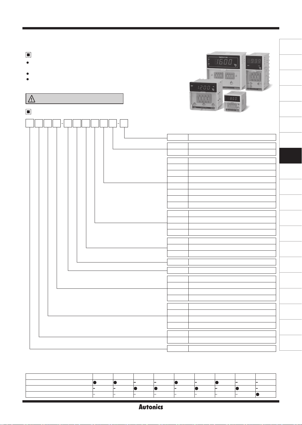
Ordering Information
3T S B N4 R P 4 C
※
1
Item
Digit
Alarm/Sub output
Size
Control output
Power supply
Control method
※
3
Temperature unit
Temperature range
※
Input type
4
※
3
New
※
4
N
C
F
0
1
2
4
8
A
C
F
P
J
K
R
R
S
C
4
B
No-mark
A
S
P
S
M
H
L
3
4
T
New type
℃
℉
-99 to 199℃, -99.9 to 199.9
0 to 99.9
℃
0 to 200℃, 0 to 200.0
0 to 400
℃
0 to 800℃/
0 to 999
0 to 1200
600 to 1600
℉
℃
℃
℃
℃
℃
DPt100Ω
J(IC)
K(CA)
R(PR)
Relay output
SSR drive output
Current output
100-240VAC 50/60Hz
ON/OFF control, Proportional control
None
Alarm output
Sub output
Dual setting output
DIN W48×H48mm (8-pin plug type)
DIN W72×H72mm
DIN W48×H96mm
DIN W96×H96mm
999 (3-digit)
9999 (4-digit)
Temperature Controller
(A)
Photoelectric
Sensors
(B)
Fiber
Optic
Sensors
(C)
Door/Area
Sensors
(D)
Proximity
Sensors
(E)
Pressure
Sensors
(F)
Rotary
Encoders
(G)
Connectors/
Connector Cables/
Sensor Distribution
Boxes/Sockets
(H)
Temperature
Controllers
(I)
SSRs / Power
Controllers
(J)
Counters
(K)
Timers
(L)
Panel
Meters
(M)
Tacho /
Speed / Pulse
Meters
(N)
Display
Units
(O)
Sensor
Controllers
(P)
Switching
Mode Power
Supplies
(Q)
Stepper Motors
& Drivers
※
2
& Controllers
(R)
Graphic/
Logic
Panels
(S)
Field
Network
Devices
(T)
Software
※
1: Name plate and connections are dierent from previous T3/T4 Series.
※
2: Sockets (PG-08, PS-08(N)) are sold separately.
※
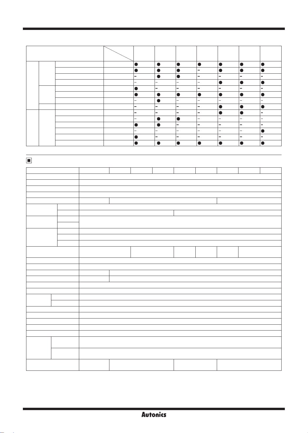
3: Output by Series
Series
T3S T3H T3HA T3HS T4M T4MA T4L T4LA T4LP
Control output
Control output+Alarm/Sub output
Dual setting output
H-107
T3 / T4 Series
※
4: Input type and temperature range by Series
Input type
0 to 400
℃
0 to 800
K(CA)
J(IC)
Thermocouples
R(PR) 600 to 1600
DPt
RTD
100Ω
※
Please contact us for temperature unit ℉ model.
℃
0 to 999
℃
0 to 1200
℃
0 to 200
℃
0 to 400
℃
0 to 800
℉
-99.9 to 199.9
-99 to 199
0 to 99.9
0 to 200.0
0 to 200
0 to 400
℃
℃
℃
℃
℃
℃
℃
Model
4
8
A
C
2
4
8
F
0
0
1
2
2
4
Series
T3S T3H T3HA T3HS
Specifications
Series T3S T3H T3HA T3HS T4M T4MA T4L T4LA T4LP
Power supply 100-240VACᜠ 50/60Hz
Allowable voltage range 90 to 110% of rated voltage
Power consumption Max. 5VA
Display method 7-segment (red) LED method
Character size (W×H)
Input type
Display
accuracy
Control
output
RTD DPt100Ω (Allowable line resistance max.5Ω per a wire)
TC K(CA), J(IC) K(CA), J(IC), R(PR)
RTD
※
1
TC
Relay OUT1: 250VACᜠ 5A, 30VDCᜡ 5A, 1c, OUT2: 250VACᜠ 2A, 30VDCᜡ 2A, 1c
SSR Max. 12VDCᜡ±2V 20mA
Current DC4-20mA (resistive load max. 500Ω)
Alarm/Sub/
Dual setting output
Sampling period 100ms
Control method ON/OFF, Proportional control
Hysteresis F.S. 0.5% F.S. 0.2 to 3% variable
Proportional band F.S. 3% F.S. 1 to 10% variable
Proportional cycle 20 sec
RESET range F.S. -3 to 3% variable
Relay life
cycle
Mechanical
Electrical OUT1: Over 100,000 times, OUT2: Over 200,000 times
Dielectric strength 2,000VAC 50/60Hz for 1min (between input terminal and power terminal)
Vibration 0.75mm amplitude at frequency of 10 to 55Hz (for 1 min) in each X, Y, Z direction for 2 hours
Insulation resistance
Noise immunity
Memory retention Approx. 10 years (when using non-volatile semiconductor memory type)
Ambient
Environment
temperature
Ambient
humidity
※
3
Weight
※
1: In case of the T3S Series and the decimal point display models
At room temperature (23ºC±5ºC): (PV ±0.5% or ±2℃, select the higher one)±1-digit
Out of room temperature range: (PV ±0.5% or ±3℃, select the higher one)±1-digit
※
2: Dual setting output of the T4LP is xed as relay output and, it is also available as alarm output.
※
3: The weight includes packaging. The weight in parenthesis is for unit only.
※
Environment resistance is rated at no freezing or condensation.
3.8×7.6mm
At room temperature (23ºC ± 5ºC): (PV ± 0.5% or ±1ºC, select the higher one) ± 1-digit
●
Out of room temperature range: (PV± 0.5% or ±2ºC, select the higher one)± 1-digit
●
-
6.0×10.0mm 8.0×14.2mm
250VACᜠ 2A 1c
-
250VAC
2A 1a
Over 5,000,000 times
Over 100MΩ (at 500VDC megger)
Square-wave noise by noise simulator (pulse width 1㎲) ±2kV R-phase and S-phase
-10 to 50℃, Storage: -20 to 60
℃
35 to 85% RH, Storage: 35 to 85% RH
Approx. 135g
(approx. 95g)
Approx. 239g
(approx. 176g)
Approx. 246g
(approx. 180g)
T4M
T4MA
ᜠ
-
Approx. 310g
(approx. 222g)
T4L
T4LA
※
2
250VACᜠ 2A 1c
T4LP
H-108
Thumbwheel Switch Setting Type
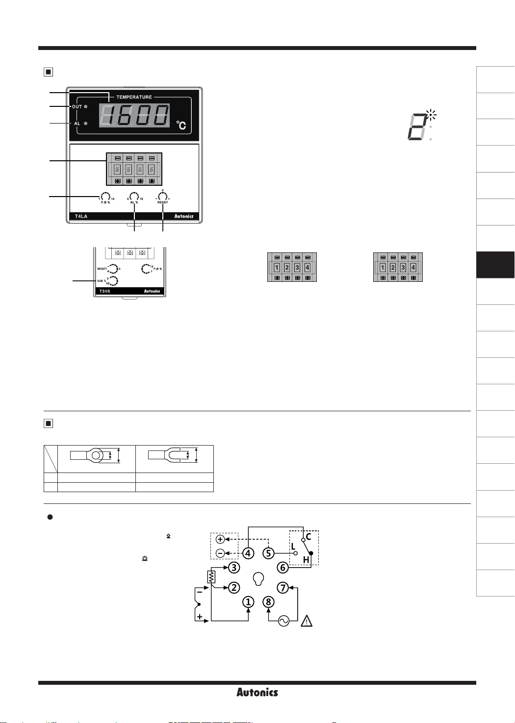
Unit Description
1
2
3
4
5
76
8
5. Hysteresis/Proportional width volume switch
ON/OFF control: Setting for hysteresis. [Setting range] F.S. 0.2 to 3% (For T3S, F.S. 0.5% xed)
Proportional control: Setting for proportional width. [Setting range] F.S. 1 to 10% (For T3S, F.S. 3% xed)
Proportional cycle: 20 sec xed
6. Alarm output value volume switch
(only for alarm output model)
It sets alarm output value. [Setting range] F.S. 0 to 10%
7. RESET volume switch
In case of proportional control, it sets oset. [Setting range] F.S. -3 to 3%
8. Temperature setting of sub output volume switch
It sets temperature of the sub output. This output operates as deviation low-limit alarm based on the set sub-output temperature
(SV). Setting range: 0 to 50
℃
1. Present temperature (PV) display
It displays present temperature.
2. Control output (OUT) indicator
It turns ON when control output is ON.
※
In case of the T3S, the upper DOT of last digit ashes.
3. Alarm output (AL) indicator
It turns ON when alarm output is ON. (only for alarm output model)
In case of the sub output model (T3HS), the sub (SUB) indicator turns ON
when sub output is ON.
4. Set value (SV) thumbwheel switch
Switch for setting temperature.
(-) button: Decreases number, (+) button: Increases number
If the setting is out of the temperature range of temperature sensor, the present
temperature (PV) display part ashes
※
The models which temperature range is 0 (-99.9 to 199.9℃, -99 to 199℃) of
SvER
and the present value in turn.
temperature sensor DPt100Ω are only set 1↔0↔ (-).
※
The dual setting output model (T4LP) has two thumbwheel switches.
LO SET
(low set output)
HI SET
(high set output)
LO SET (low set output) heating control, HI SET (high set output): cooling control
(except T3S)
(only for T3HS)
Connections
※
Use teminals of size specied below.
a
b
<Round>
<Forked>
a Min. 3.5mm Min. 3.5mm
b Max. 7.2mm Max. 7.2mm
T3S
SSR OUT: 12VDC±2V
20mA Max.
CURRENT OUT: DC4-20mA
Load 500Ω Max.
a
b
RELAY OUT:
250VAC 5A 1c
30VDC 5A 1c
A
RESISTIVE LOAD
B'
(A)
Photoelectric
Sensors
(B)
Fiber
Optic
Sensors
(C)
Door/Area
Sensors
(D)
Proximity
Sensors
(E)
Pressure
Sensors
(F)
Rotary
Encoders
(G)
Connectors/
Connector Cables/
Sensor Distribution
Boxes/Sockets
(H)
Temperature
Controllers
(I)
SSRs / Power
Controllers
(J)
Counters
(K)
Timers
(L)
Panel
Meters
(M)
Tacho /
Speed / Pulse
Meters
(N)
Display
Units
(O)
Sensor
Controllers
(P)
Switching
Mode Power
Supplies
(Q)
Stepper Motors
& Drivers
& Controllers
(R)
Graphic/
Logic
Panels
(S)
Field
Network
Devices
(T)
Software
SENSOR
B
TC RTD
SOURCE
100-240VAC
50/60Hz 5VA
H-109

T3 / T4 Series
T4M/T4MA
T3H/T3HA/T3HS
SSR OUT: 12VDC±2V
20mA Max.
CURRENT OUT: DC4-20mA
Load 500Ω Max.
SSR OUT: 12VDC±2V
20mA Max.
CURRENT OUT: DC4-20mA
Load 500Ω Max.
SENSOR
TC
B' B A
RELAY OUT:
250VAC 5A 1c
30VDC 5A 1c
RESISTIVE LOAD
RELAY OUT:
250VAC 5A 1c
30VDC 5A 1c
RESISTIVE LOAD
T3HA
ALARM OUT:
250VAC 2A 1c
T3HS
SUB OUT:
250VAC 2A 1c
30VDC 2A 1c
RTD
T4MA
ALARM OUT:
250VAC 2A 1a
A
SOURCE
100-240VAC
50/60Hz 5VA
T4L/T4LA/T4LP
SSR OUT: 12VDC±2V
20mA Max.
CURRENT OUT: DC4-20mA
Load 500Ω Max.
SOURCE
100-240VAC
50/60Hz 5VA
SOURCE
100-240VAC
50/60Hz 5VA
RELAY OUT:
250VAC 5A 1c
30VDC 5A 1c
RESISTIVE LOAD
T4LA
ALARM OUT:
250VAC 2A 1c
T4LP
HI SET OUT:
250VAC 2A 1c
30VDC 2A ac
B
SENSOR
B'
TCRTD
A
B
SENSOR
B'
TCRTD
H-110

Thumbwheel Switch Setting Type
Dimensions
T3S
12.3
48
10.5
T3H
48
96
※
T3HA, alarm output model, has the alarm output value volume switch.
※
T3HS, sub output model, has the temperature setting of sub output volume switch.
13
T4M
72
90.1
63.8
11.8
83
70
89.3
75
(A)
(unit: mm)
45
91.5
Photoelectric
Sensors
(B)
Fiber
Optic
Sensors
(C)
Door/Area
Sensors
(D)
Proximity
Sensors
(E)
Pressure
Sensors
(F)
Rotary
Encoders
(G)
Connectors/
Connector Cables/
Sensor Distribution
Boxes/Sockets
(H)
Temperature
Controllers
(I)
SSRs / Power
Controllers
(J)
Counters
(K)
Timers
(L)
Panel
Meters
(M)
Tacho /
Speed / Pulse
Meters
(N)
Display
Units
※
T4MA, alarm output model, has the alarm output value volume switch.
T4L
96
※
T4LA, alarm output model, has the alarm output value volume switch.
※
T4LP, dual setting output model, has the two thumbwheel switches.
12.5
82.5
(O)
67.5
70
Sensor
Controllers
(P)
Switching
Mode Power
Supplies
(Q)
Stepper Motors
& Drivers
& Controllers
(R)
Graphic/
Logic
Panels
(S)
Field
Network
Devices
(T)
Software
91.5
H- 111

T3 / T4 Series
Bracket
●T3S
45.4
● T3H/T4M/T4L
3.34
61
4.5
4.2
41
3.9
15
12.2
7.4
48
Terminal cover (sold separately)
● RMA-COVER (72×72mm)
70
68.5
3
64
13
Panel cut-out
47.8
61
● RLA-COVER (96×96mm)
94
91.5
13
3
23.9
86
46
37.5
40.5
12
● RHA-COVER (48×96mm)
47.2
91.5
4
86
13
H-112
A
D
B
C
Series
T3S Min. 65 Min. 65 45
T3H Min. 65 Min. 115 45
T4M Min. 90 Min. 90 68
T4L Min. 115 Min. 115 92
Size
A B C D
+ 0.6
+ 0.6
45
0
0
+ 0.6
+ 0.8
92
0
0
+ 0.7
+ 0.7
68
0
0
+ 0.8
+ 0.8
92
0
0

Thumbwheel Switch Setting Type
Function
1. Control method
1)ON/OFF control
Comparing the present measured temperature and the set temperature,
the temperature controller turns ON/OFF of the load power. Interval
between ON and OFF of control output is set by the set hysteresis. When
hysteresis of control output is too narrow, hunting (overshoot, chattering)
may occur by external noise.
[Setting range of Hysteresis] F.S. 0.2 to 3%
Set temperature
2)Proportional control
Proportional control has control output which is proportional to deviation from
the present temperature to the set temperature in the proportional band to the
set temperature.
Temperature
Set temperature
(SV)
(In case of T3S, F.S. 0.5% xed)
Temperature
Overshoot
(SV)
ON
Output
OFF
Measured temperature
Measured temperature
(PV)
(PV)
Oset
Hunting width
※
Control method
setting switch
Front
Hysteresis
※
Control method
setting switch
Front
Proportional
band
(A)
Photoelectric
Sensors
(B)
Fiber
Optic
Sensors
(C)
Door/Area
Sensors
P
P
Time
F
F
(D)
Proximity
Sensors
(E)
Pressure
Sensors
(F)
Rotary
Encoders
(G)
Connectors/
Connector Cables/
Sensor Distribution
Boxes/Sockets
(H)
Temperature
Controllers
(I)
SSRs / Power
Controllers
(J)
Counters
(K)
Timers
Time
※
T: Proportional band is
Output
ON
OFF
xed as 20 sec.
It is available to control without overshoot or hunting comparing ON/OFF control but it may cause oset. Correct the oset
with the RESET volume switch.
[Setting range of Proportional band] F.S. 1 to 10% (In case of T3S, F.S. 3% xed)
[Setting range of RESET] F.S. -3 to 3%
2. Alarm output
Alarm temperature is applied to the high/low-limit based on the set temperature. Alarm output operates deviation high/low-limit.
Setting range of Alarm temperature: F.S. 0 to 10%
E.g.) When F.S. is 400℃ and max. alarm temperature (F.S. 10%) is 40℃.
When the set temperature is set as 100℃, alarm output operation range is 140℃ to 60℃.
Temperature
Alarm
output
140℃
138℃
100℃
62℃
60℃
ON
OFF
Hysteresis 2℃ xed
Hysteresis 2℃ xed
Time
(L)
Panel
Meters
(M)
Tacho /
Speed / Pulse
Meters
(N)
Display
Units
(O)
Sensor
Controllers
(P)
Switching
Mode Power
Supplies
(Q)
Stepper Motors
& Drivers
& Controllers
(R)
Graphic/
Logic
Panels
(S)
Field
Network
Devices
(T)
Software
H-113

T3 / T4 Series
3. Sub output
Only the T3HS model has sub output. This output operates as deviation low-limit alarm.
[Setting range of Sub output]: 0 to 50
E.g.)Set temperature is set as 100℃ and sub-output is set as 20
4. Dual setting output
Only the T4LP model has dual setting output.
-LO SET (low set output: ON/OFF control (Hysteresis: F.S. 0.2 to 3%),
-HI SET (high set output): Absolute value high-limit alarm output (Hysteresis: 2℃ xed)
E.g.)T4LP, temperature sensor: DPt100, temperature range: 0 to 400
Type Set temperature Output Hysteresis
LO SET
(low set output)
HI SET
(High set output)
LO SET
(low set output)
HI SET
(high set output)
(Only for T3HS)
Temperature
Sub output
Temperature
℃
100℃
82℃
80℃
ON
OFF
(Only for T4LP)
Proportional control (Proportional band: F.S. 1 to 10%)
120℃
118℃
100℃
80℃
78℃
ON
OFF
ON
OFF
80
120
℃
℃
ON/OFF control
Absolute value
high-limit alarm output
℃
℃
0.5%
(400×0.5%=2℃)
2℃ (xed)
Hysteresis 2℃ xed
Time
Hysteresis 2℃ xed
Hysteresis 0.5% (2℃)
Time
Display When Power Is ON
When power is supplied, whole display parts turn ON for 1 sec. It displays model type (digits, size, alarm/sub output and
control output, sensor, temp. range, unit). Afterward, it returns to RUN mode.
Whole parts turn
ON
Displays
size, alarm/sub
→
When input sensor break/sensor is not connected, it displays [
input temperature and controls temperature.
※
During displaying model type, control output does not operate.
H-114
digits,
output
Displays control
output, sensor,
temp. range, unit
→
RUN mode
→
When input sensor
Normal operation
break/sensor is not
connected
OPEN
]. In case of normal operation, it displays the present

Thumbwheel Switch Setting Type
Control Method (ON/OFF, Proportional Control) Setting
Before supplying power, remove the case and set the control method by the control method setting switch.
T3S Other Series
①
②
②
①
Control method setting switch
Front
P: Proportional control (
Press the 8-pin plug with your thumb. Insert
a at head driver to the ① groove and uplift
the case (same as the other side). Push it to
the ② direction and the case is removed.
Press the ① with your thumb. Pull the case to the
direction and it is removed.
②
F: ON/OFF control
Error Display and Output Operation
Display Description
OPEN
HHHH
LLLL
SvER
※
1: T4LP (Dual setting output) is the single output.
※
2: When
Flashes when a temperature sensor is
broken or not connected.
Flashes when the measured input value
is higher than the temperature range of
the sensor.
Flashes when the measured input value
is lower than the temperature range of
the sensor.
Flashes with the present value when the
※
2
set value is out of the temperature range
of the sensor.
OFF.
SvER
OPEN/ HHHH/LLLL
and
occur at the same time,
Control
output
※
1
Alarm
output
SvER
Sub
Dual
output
output
OPEN/ HHHH/LLLL
and
Troubleshooting
Check the status of the temperature
sensor. When the sensor is connected
correctly, it is clear.
When the measured temperature is within
the temperature range of the sensor, it is
clear.
The set value should be within the temperature range of the sensor.
ash in turn and all output turns
(A)
Photoelectric
Sensors
(B)
Fiber
Optic
Sensors
(C)
Door/Area
)
Sensors
(D)
Proximity
Sensors
(E)
Pressure
Sensors
(F)
Rotary
Encoders
(G)
Connectors/
Connector Cables/
Sensor Distribution
Boxes/Sockets
(H)
Temperature
Controllers
(I)
SSRs / Power
Controllers
(J)
Counters
(K)
Timers
(L)
Panel
Meters
(M)
Tacho /
Speed / Pulse
Meters
(N)
Display
Units
P
F
default
●: ON
○: OFF
H-115
(O)
Sensor
Controllers
(P)
Switching
Mode Power
Supplies
(Q)
Stepper Motors
& Drivers
& Controllers
(R)
Graphic/
Logic
Panels
(S)
Field
Network
Devices
(T)
Software
 Loading...