

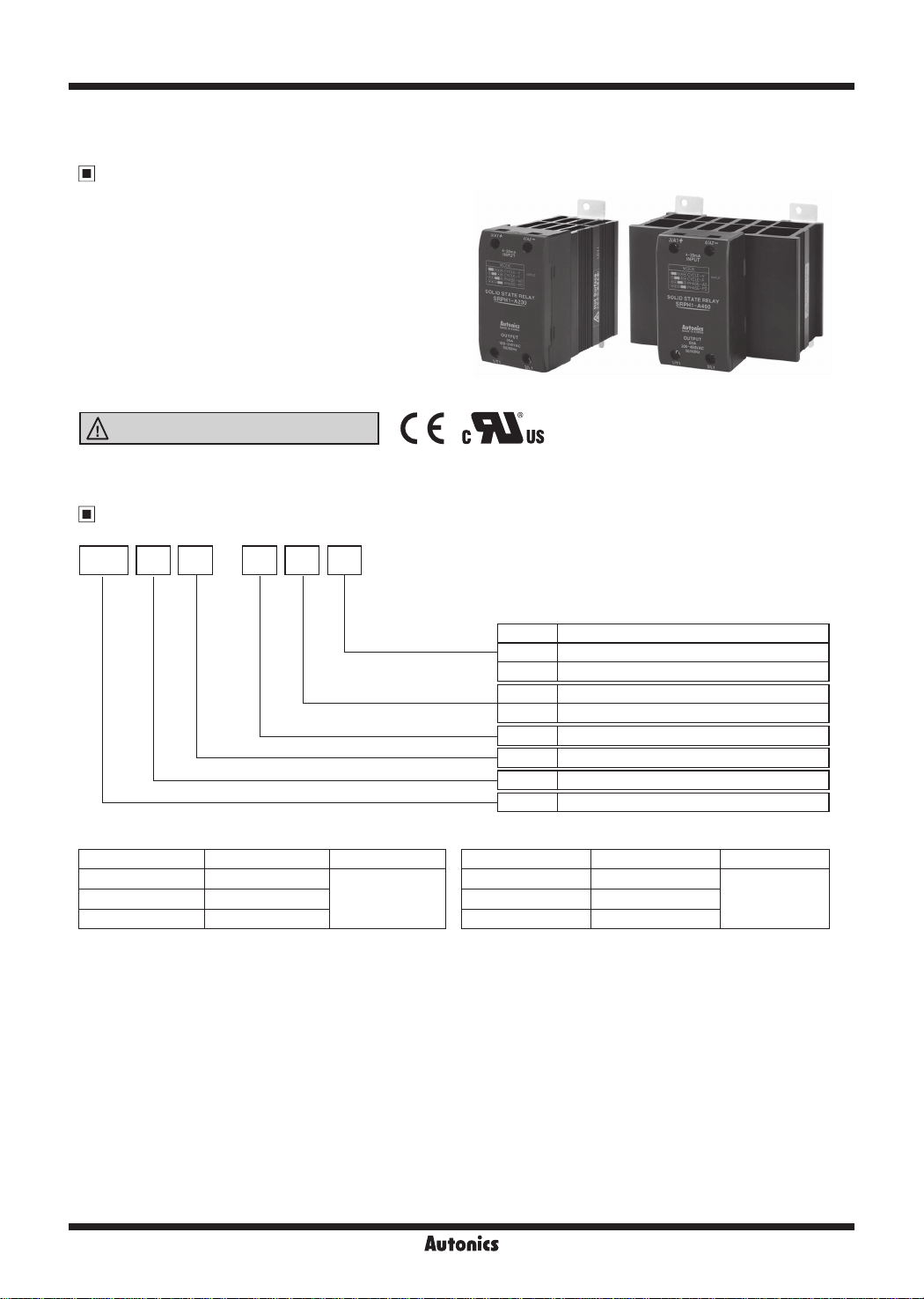
SRPH1 Series
Single-Phase, Analog Input Type SSR
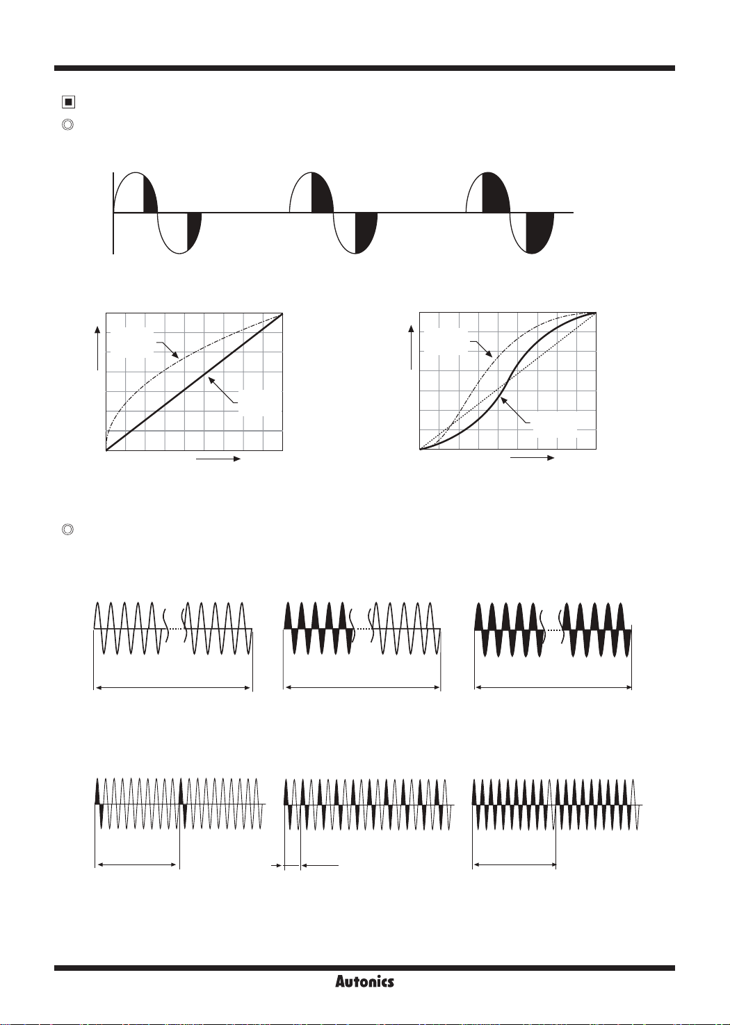
Features
● Phase control and cycle control possible with 4-20 mA
analog input
- Phase control
(output power control / phase angle control)
- Cycle control (xed cycle / variable cycle)
● DIN rail mount or panel mount installation
● Dielectric strength: 4000 VAC
● High heat dissipation efciency with ceramic PCB and
integrated heatsink
● Zero cross turn-on, random turn-on models available
● Input indicator (green LED)
Please read “Safety considerations” in operation
manual before using.
c=..__I&
SRP AH 1 2 30-
__
Ordering Information
I
CE
c'i\lus
Rated load current
(resistive load)
Rated load voltage
Rated input current
Control phase
Type
Item
Model Rated load current Rated load voltage
SRPH1-A220 20A
L__________J___--------'------11------+----------i
SRPH1-A260 60A
100-240VAC SRPH1-A230 30A
20 20A
30 30A
60 60A
2 100-240VAC
4 200-480VAC
A 4-20mA analog input
1 Single-phase
H Integrated heatsink type
SRP Solid State Relay (analog input type)
Model Rated load current Rated load voltage
SRPH1-A420 20A
200-480VAC SRPH1-A430 30A
SRPH1-A460 60A
I-18
Autonics
Single-Phase, Analog Input Type SSR
Specications
Input
Rated input current
Max. allowable input current
Pick-up current Min. 4 2mA
Static off current Max. 0.2mA
Power factor Min. 0 9 (max. 25° of difference between voltage phase and current phase)
Start-up time 60Hz: 200ms, 50Hz: 250ms
Operation time 60Hz: 16.6ms, 50Hz:20ms
※
Operation mode
※
1: You can change operation mode by jumper pin. Default is Phase control (Power equality division type).
Output
0
1
Rated load voltage range 100-240VACrmsᜠ (50/60Hz) 200-480VACrmsᜠ (50/60Hz)
Allowable load voltage range 90-264VACrmsᜠ (50/60Hz) 200-528VACrmsᜠ (50/60Hz)
Rated load
current
Resistive load
(AC-51)
I
Min. load current 0 5Arms 0.5Arms
Max. 1 cycle surge current
(60Hz)
Max. non-repetitive surge
2
current (I
t, t=8.3ms)
Peak voltage (non-repe i ive)
Leakage current (Ta=25℃) Max. 10mArms (240VACᜠ/60Hz) Max. 10mArms (480VACᜠ/60Hz)
Output on voltage drop[Vpk]
(Max. load current)
Static off-state dv/dt 500V/
※
1: AC-51 are utilization category at IEC 60947-4-3.
General Specifications
0
Phase control
(phase equality division type)
Phase control
(power equality division type)
Frequency reading function Ye s
Dielectric strength (Vrms) 4000VACᜠ 50/60Hz for 1min. (Input-Output, Input/Output-Case)
Insulation resistance Over 100MΩ (at 500VDC megger)
Vibra ion 10 to 55Hz double amplitude 0.75mm in each X, Y, Z direction for 1 hour
Indicator Input indicator: Green LED
Environment
Ambient temp.
I
Ambient humi. 45 to 85%RH, storage: 45 to 85%RH
I
Input terminal connection Min. 1×0.5mm
Output terminal connection
Input terminal xed torque 0.75 to 0 95N.m
Output terminal xed torque 1.6 to 2.2N m
Approval
Unit weight
※
Environment resistance is rated at no freezing or condensa ion.
※
For wiring the terminal, an O-ring terminal must be used.
4-20mA
50
mA
Phase control (phase equality division type, power equality division type)
Cycle control (xed cycle, variable cycle)
20Arms 30Arms 60Arms 20Arms 30Arms 60Arms
※
1
300A 500A 1000A 300A 500A 1000A
350A2s 1000A2s 4000A2s 350A2s 1000A2s 4000A2s
600V 1000V
Max. 1.6V
㎲
5 to 99%
10 to 99%
-20 to 70℃, storage: -20 to 100
℃
(The rated load current capacity is different depending on ambient temperature. Refer to '
2
(1×AWG20) Max. 1×1.5mm2 (1×AWG6) or Max. 2×1.5mm2 (2×AWG16)
2
Min. 1×1.5mm
※
Connect appropriate cable for the load current capacity to output terminal.
(€
c'i\lus
(1×AWG16) Max.1×16mm2 (1×AWG6) or Max. 2×6mm2 (2×AWG10)
• SRPH1-A220, SRPH1-A230, SRPH1-A420, SRPH1-A430 : Approx. 410g
• SRPH1-A260, SRPH1-A460 : Approx. 680g
~
SSR Derating Curve'.)
(A)
Photoelectric
Sensors
(B)
Fiber
Optic
Sensors
(C)
Door/Area
Sensors
(D)
Proximity
Sensors
(E)
Pressure
Sensors
(F)
Rotary
Encoders
(G)
Connectors/
Connector Cables/
Sensor Distribution
Boxes/Sockets
(H)
Temperature
Controllers
(I)
SSRs / Power
Controllers
(J)
Counters
(K)
Timers
(L)
Panel
Meters
(M)
Tacho /
Speed / Pulse
Meters
(N)
Display
Units
(O)
Sensor
Controllers
(P)
Switching
Mode Power
Supplies
(Q)
Stepper Motors
& Drivers
& Controllers
(R)
Graphic/
Logic
Panels
(S)
Field
Network
Devices
(T)
Software
Autonics
I-19
SRPH1 Series
Dimensions & Mounting
Dimensions
● Rated load current 20A/30A
Ø4.5
Input indicator
(green LED)
● Rated load current 60A
Ø4.5
Input indicator
(green LED)
3.5
80
90
4.5
3.5
45
81.5
3.5
100
Ø4.5
I
I
I
I
3.5
(unit: mm)
(()
Hole cut-out for panel front mounting
● Rated load current
20A/30A
2-M4×0.7 Tap
~
I
~~
~
~i
-~
00
0~
.,
~
● Rated load current
60A
81.5
4-M4×0.7 Tap
90
90
<El
I
31
100
-
※
Screw tightening torque for mounting: 1.8 to 2.5N m
~
7 77
'I
I
~
80
90
100
I
~
•ii
~~
-~
00
0~
.,
<El
~
~
4.5
3.5
45
110
4 5
3.5
31
"
DIN rail mounting Installation interval
● DIN rail attachment
②
※
DIN rail must be grounded.
● DIN rail detachment
②
①
35mm DIN rail
35mm DIN rail
①
(-) driver
100100100
20
100
Panel
Panel
-
a
※
For mounting multiple
SSR, please keep certain
installation intervals for
heat prevention.
For horizontal installation
(when the heights of input
part and output part are
equal), it is recommended
to apply 50% of rated
load current.
High temperature
caution
Make sure do not touch the
heat sink or the unit body
while power is supplied or
right after load power is
turned off.
If not, it may cause a burn.
I-20
Autonics
Single-Phase, Analog Input Type SSR
Connections
3/A1+
4-20
mA
4/A2- 2/L1
※
1: As above connection, connect a capacitor. It is proper to EMC.
SSR module
Input Output
SRPH1 Series
CAP: Load voltage 100-240VAC → 1uF/250VAC, Load voltage 200-480VAC → 0.47uF/500VAC
1/T1
Load
CAP
※
1
Rapid fuse
Load Source
(AC)
SSR Derating Curve
SRPH1-A220/A420 SRPH1-A230/A430 SRPH1-A260/A460
60
50
40
Load current [A]
30
20
16
'"
10 10
0
0 0 0
-
10 10 1020 20 2030 30
Ambient temperature [℃] Ambient temperature [℃] Ambient temperature [℃]
,- -
40 40 4050 50 5060 60 6070 70 7080 80 8090 90 90
(Q)
60 60
50 50
40 40
Load current [A]
30
20
r-
- - - - - - - _
16
0 0
...............
...,.
Please supply less than 50% of the rated load current when installing several SSRs closely due to decreasing
effectiveness of protection against heat.
(Q)
Load current [A]
30
...
-
25
20
10
,,
I'-.
I
I
'i'\.
I
-
-
30
-·-
I
I
I
35
-
Operation Setting
● Detach front cover
Press front cover connection 4 parts at right and left side
with (-) driver, and front cover is detached.
※
Before detaching front cover, you must cut off load
current and input.
Flat head (-)
driver
'
- -
'
(A)
Photoelectric
Sensors
(B)
Fiber
Optic
Sensors
(C)
Door/Area
Sensors
(D)
Proximity
Sensors
(E)
Pressure
Sensors
(F)
Rotary
Encoders
(G)
Connectors/
Connector Cables/
Sensor Distribution
Boxes/Sockets
(H)
Temperature
'lo
Controllers
(I)
SSRs / Power
Controllers
(J)
Counters
(K)
Timers
(L)
Panel
Meters
(M)
Tacho /
Speed / Pulse
Meters
(N)
Display
Units
● Jumper pin setting
Operation mode is decided by jumper position.
After changing operation mode, re-supply input signal.
4-20mA
input
r 7
@
fr~···
Jumper pin
Jumper
...........
LI-
Jumper
..
Jumper pin
I!
111
1 2 3 4
CYCLE-V: Cycle control (variable cycle)
1.
CYCLE-F: Cycle control (xed cycle)
2.
PHASE-AD: Phase control (phase equality division type)
3.
PHASE-PD: Phase control (power equality division type)
4.
(factory default)
l
1
Autonics
I-21
(O)
Sensor
Controllers
(P)
Switching
Mode Power
Supplies
(Q)
Stepper Motors
& Drivers
& Controllers
(R)
Graphic/
Logic
Panels
(S)
Field
Network
Devices
(T)
Software
SRPH1 Series
Operation Mode
Phase control
● Output waveform of phase control
• When control input signal is 25%
※
1
• When control input signal is 50%
• When control input signal is 75%
,________..,.__F'=,-~C\,-------~
※
1: The black parts of output waveform are output on the load.
● Power equality division type ● Phase equality division type
100%
Output
DC 4
Output
voltage
curve
mA
Control input
Output
power
curve
DC 20
100%
mA
100%
Output
DC 4
Output
voltage
curve
mA
Control input
Output
power
curve
DC 20
100%
mA
Controls output power which is
proportional to control input (4-20mA) level.
(Q)
Cycle control
Controls phase angle which is proportional
control input (4-20mA) level.
● Fixed cycle
Controls continuously the number of full cycle which is supplied to load every 1 sec by being proportional to control input
(4-20mA).
• When control input signal is 0%
T: Cycle (1 sec) T: Cycle (1 sec)
• When control input signal is 50%
• When control input signal is 100%
T: Cycle (1 sec)
● Variable cycle
Controls fast and accurately the subject with optimized the number of AC voltage cycle which is supplied to load by being
proportional to control input (4-20mA).
• When control input signal is 10%
T cycle
• When control input signal is 50%
T cycle T cycle
--+
-+----
• When control input signal is 90%
I-22
Autonics
Single-Phase, Analog Input Type SSR
Proper Usage
High temperature caution
Make sure do not touch the heat sink or the unit body while power is supplied or right after load power is
turned off. If not, it may cause a burn.
Cautions during use
1. Ventilate for smooth convection current. If not, congested heat transfer may cause product failure or malfunction.
2. Must ground heatsink or mounted DIN rail. Failure to follow this instruction may cause electric shock.
3. For mounting multiple SSR, please keep certain installation intervals for heat prevention. For horizontal installation (when
the heights of input part and output part are equal), it is recommended to apply less than 50% of the rated load current.
4. Make sure do not touch the heatsink or the unit body while power is supplied or right after load power is turned OFF.
If not, it may cause a burn.
5. Connect the proper cable for the rated load current with output terminal.
6. Use rapid fuse of which I
short-circuit please replace the fuse which has same specication.
7. In case that load's current is lower than SSR min. load current, connect dummy resistance to the load in parallel so as to
make load's current higher than SSR min. load current.
8. Make sure that the screw on output terminal is tightly fastened. Using the unit with loose bolt may cause product failure
or malfunction.
9. Do not touch the load's terminal even if output is OFF. It may cause electric shock.
10. The input of the 4-20mA should be supplied by the insulated and limited voltage/current or by class 2 power supply.
11. Avoid following environments to install this unit.
Where temperature/humidity is beyond the specication
①
Where dew condensation occurs due to temperature change
②
Where inammable or corrosive gas exists
③
Where direct rays of light exist
④
Where severe shock, v bration or dust exists
⑤
Where near facilities generating strong magnetic forces or electric noise
⑥
12. This product may be used in the following environments.
Indoors
①
Max. altitude: 2,000m
②
Pollution degree 2
③
Installation category
④
2
t is under 1/2 of SSR I2t in order to protect the unit from load's short-circuit current. In case of a
Ⅲ
(A)
Photoelectric
Sensors
(B)
Fiber
Optic
Sensors
(C)
Door/Area
Sensors
(D)
Proximity
Sensors
(E)
Pressure
Sensors
(F)
Rotary
Encoders
(G)
Connectors/
Connector Cables/
Sensor Distribution
Boxes/Sockets
(H)
Temperature
Controllers
(I)
SSRs / Power
Controllers
(J)
Counters
(K)
Timers
(L)
Panel
Meters
(M)
Tacho /
Speed / Pulse
Meters
(N)
Display
Units
Autonics
I-23
(O)
Sensor
Controllers
(P)
Switching
Mode Power
Supplies
(Q)
Stepper Motors
& Drivers
& Controllers
(R)
Graphic/
Logic
Panels
(S)
Field
Network
Devices
(T)
Software
 Loading...