

Autonics SRH1 Series Catalog Page
Single-Phase, Integrated Heatsink Type SSRSRH1 Series
Single-Phase, Integrated Heatsink Type SSR
Features
● High heat dissipation efciency with ceramic PCB
and integrated heatsink
● Input Indicator (green LED)
● DIN rail mount or panel mount installation
[Voltage input type]
Zero cross turn-on, random turn-on models
available
[Current input type]
Phase control and cycle control possible
- Phase control
(power equality division/phase equality division)
- Cycle control (xed cycle/variable cycle)
Please read “Safety considerations” in operation
manual before using.
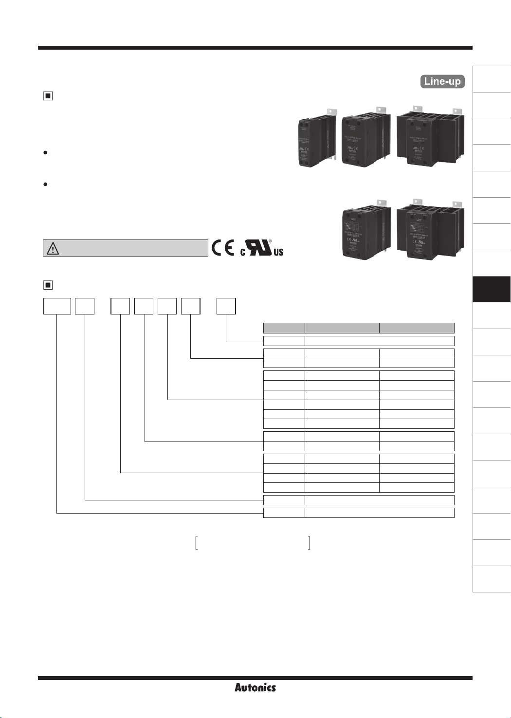
Ordering Information
SRH 11 2 15- -
Rated load current
(resistive load)
Rated load voltage
Rated input
Control phase
Item
※
This ordering informaion is only for reference. For ordering a specic model, check the ordering information of the model.
※
For more information about models, refer to the B-16 page for the voltage input type
N
Version
Function
B-22 page for the current input type
[Voltage input type]
Rated load
current
10A/15A/20A 60A30A/40A
[Current input type]
Rated load
current
Voltage input type Current input type
N Renewal
No Mark Zero cross turn-on
R Random turn-on
10 10A
15 15A
20 20A 20A
30 30A 30A
40 40A
60 60A 60A
2 24-240VAC 100-240VAC
4 48-480VAC 200-480VAC
1 4-30VDC
2 24VAC
4 90-240VAC
A
-
1 Single-phase
SRH Solid State Relay (integrated heatsink type)
20A/30A 60A
-
-
-
-
-
-
-
-
4-20mA
(A)
Photoelectric
Sensors
(B)
Fiber
Optic
Sensors
(C)
Door/Area
Sensors
(D)
Proximity
Sensors
(E)
Pressure
Sensors
(F)
Rotary
Encoders
(G)
Connectors/
Connector Cables/
Sensor Distribution
Boxes/Sockets
(H)
Temperature
Controllers
(I)
SSRs / Power
Controllers
(J)
Counters
(K)
Timers
(L)
Panel
Meters
(M)
Tacho /
Speed / Pulse
Meters
(N)
Display
Units
(O)
Sensor
Controllers
(P)
Switching
Mode Power
Supplies
(Q)
Stepper Motors
& Drivers
& Controllers
(R)
Graphic/
Logic
Panels
(S)
Field
Network
Devices
I-15
(T)
Software
SRH1 Series
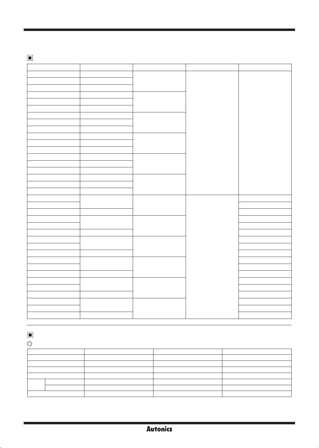
Single-Phase, Integrated Heatsink Type SSR [Voltage Input Type]
Model
Model Rated input voltage Rated load voltage Rated input current Function
SRH1-1210-N 4-30VDC
SRH1-2210-N 24VAC
SRH1-4210-N 90-240VAC
SRH1-1215-N 4-30VDC
SRH1-2215-N 24VAC
SRH1-4215-N 90-240VAC
SRH1-1220-N 4-30VDC
SRH1-4220-N 90-240VAC
SRH1-1230-N 4-30VDC
SRH1-4230-N 90-240VAC
SRH1-1240-N 4-30VDC
SRH1-4240-N 90-240VAC
SRH1-1260-N 4-30VDC
SRH1-4260-N 90-240VAC
SRH1-1410-N
SRH1-1410R-N Random turn-on
SRH1-2410-N 24VAC Zero cross turn-on
SRH1-1415-N
SRH1-1415R-N Random turn-on
SRH1-2415-N 24VAC Zero cross turn-on
SRH1-1420-N
SRH1-1420R-N Random turn-on
SRH1-2420-N 24VAC Zero cross turn-on
SRH1-1430-N
SRH1-1430R-N Random turn-on
SRH1-2430-N 24VAC Zero cross turn-on
SRH1-1440-N
SRH1-1440R-N Random turn-on
SRH1-2440-N 24VAC Zero cross turn-on
SRH1-1460-N
SRH1-1460R-N Random turn-on
SRH1-2460-N 24VAC Zero cross turn-on
4-30VDC
4-30VDC
4-30VDC
4-30VDC
4-30VDC
4-30VDC
10A
15A
20ASRH1-2220-N 24VAC
30ASRH1-2230-N 24VAC
40ASRH1-2240-N 24VAC
60ASRH1-2260-N 24VAC
10A
15A
20A
30A
40A
60A
24-240VAC Zero cross turn-on
Zero cross turn-on
Zero cross turn-on
Zero cross turn-on
48-480VAC
Zero cross turn-on
Zero cross turn-on
Zero cross turn-on
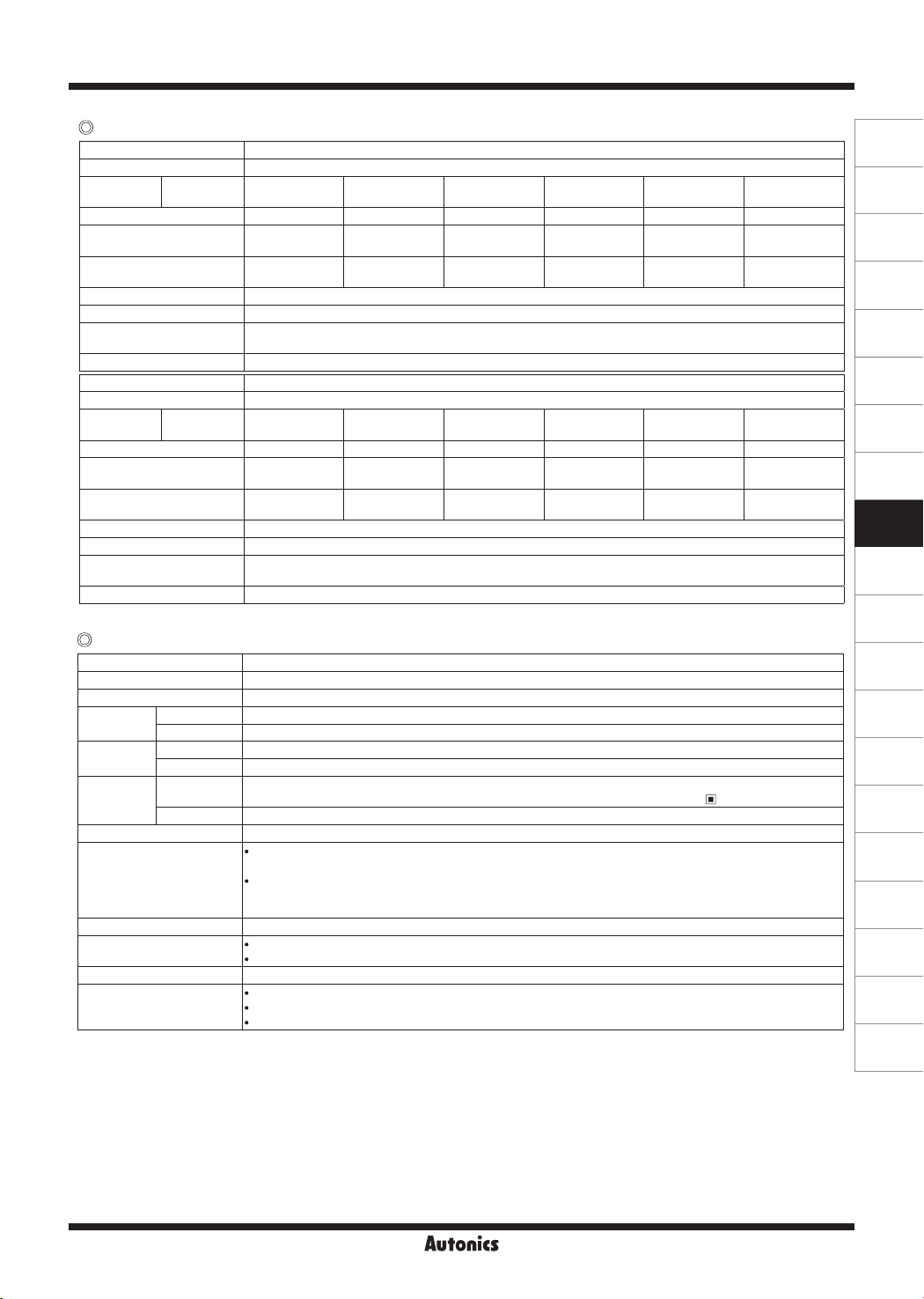
Specications
Input
Rated input voltage range
Allowable input voltage range 4-32VDC
Max. input current 18mA 15mArms (24VACrmsᜠ) 18mArms (240VACrmsᜠ)
Pick-up voltage Min. 4VDC
Drop-out voltage Max. 1VDC
Zero cross turn-on Max. 0.5 cycle of load source + 1ms Max. 2 cycle of load source + 1ms Max. 2 cycle of load source + 1ms
Turn-on
time
Random turn-on Max. 1ms
Turn-off time Max. 0.5 cycle of load source + 1ms Max. 2 cycle of load source + 1ms Max. 2 cycle of load source + 1ms
4-30VDC
ᜡ
ᜡ
ᜡ
ᜡ
I-16
24VACrmsᜠ (50/60Hz) 90-240VACrms
19-30VACrmsᜠ (50/60Hz) 85-264VACrmsᜠ (50/60Hz)
Min. 19VACrms
Max. 4VACrms
- -
ᜠ
ᜠ
Min. 85VACrms
Max. 10VACrms
(50/60Hz)
ᜠ
ᜠ
ᜠ
Single-Phase, Integrated Heatsink Type SSR
[Voltage Input Type]
Output
Rated load voltage range
24-240VACrms
Allowable load voltage range 24-264VACrmsᜠ (50/60Hz)
Rated load
current
Resistive load
※
1
(AC-51)
10Arms 15Arms 20Arms 30Arms 40Arms 60Arms
Min. load current 0.15Arms 0.15Arms 0.2Arms 0.5Arms 0.5Arms 0.5Arms
Max. 1 cycle surge current
(60Hz)
Max. non-repetitive surge
current (I2t, t=8.3ms)
160A 160A 250A 400A 500A 1000A
130A2s 130A2s 300A2s 910A2s 1000A2s 4000A2s
Peak voltage (non-repetitive) 600V
Leakage current (Ta=25℃) Max. 10mArms (240VACᜠ/60Hz)
Output on voltage drop [Vpk]
(max. load current)
Static off state dv/dt 500V/
Rated load voltage range
Max. 1.6V
㎲
48-480VACrms
Allowable load voltage range 48-528VACrmsᜠ (50/60Hz)
Rated load
current
Resistive load
※
1
(AC-51)
10Arms 15Arms 20Arms 30Arms 40Arms 60Arms
Min. load current 0.5Arms 0.5Arms 0.5Arms 0.5Arms 0.5Arms 0.5Arms
Max. 1 cycle surge current
(60Hz)
Max. non-repetitive surge
current (I2t, t=8.3ms)
300A 300A 300A 500A 500A 1000A
350A2s 350A2s 350A2s 1000A2s 1000A2s 4000A2s
Peak voltage (non-repetitive) 1200V (zero cross turn-on), 1000V (random turn-on)
Leakage current (Ta=25℃) Max. 10mArms (480VACᜠ/60Hz)
Output on voltage drop [Vpk]
(max. load current)
Static off state dv/dt 500V/
※
1: AC-51 is utilization category at IEC60947-4-3.
Max. 1.6V
㎲
(50/60Hz)
ᜠ
(50/60Hz)
ᜠ
General specifications
Dielectric strength (Vrms) 2500VAC 50/60Hz 1 min (input-output, input/output-case)
Insulation resistance Over 100MΩ (at 500VDC megger) (input-output, input/output-case)
Indicator Input indicator: green LED
Vibration
Shock
Environment
Input terminal connection Min. 1×0.5mm2 (1×AWG20), max. 1×1.5mm2 (1×AWG16) or 2×1.5mm2 (2×AWG16)
Output terminal connection
Input terminal xed torque 0.75 to 0.95N.m
Output terminal xed torque
Approval
Weight
※
1: The weight includes packaging. The weight in parenthesis is for unit only.
※
Environment resistance is rated at no freezing or condensation.
※
For wiring the terminal, round terminal must be used.
Mechanical 0.75mm amplitude at frequency of 10 to 55Hz (for 1 min) in each X, Y, Z direction for 1 hour
Malfunction 0.5mm amplitude at frequency of 10 to 55Hz (for 1 min) in each X, Y, Z direction for 10 min
Mechanical 300m/s² (approx. 30G) in each X, Y, Z direction for 3 times
Malfunction 100m/s² (approx. 30G) in each X, Y, Z direction for 3 times
Ambient temp.
-30 to 80℃ (in case of the rated input voltage 90-240VACᜠ: -20 to 70℃), storage: -30 to 100℃
( The rated load current capacity is different depending on ambient temperature. Refer to ' SSR Derating Curve'.)
Ambient humi. 45 to 85%RH, storage: 45 to 85%RH
Rated load current 10A/15A/20A
: Min. 1×0.75mm2 (1×AWG18), max. 1×4mm2 (1×AWG12) or 2×2.5mm2 (2×AWG14)
Rated load current 30A/40A/60A
: Min. 1×1.5mm2 (1×AWG16), max. 1×16mm2 (1×AWG6) or 2×6mm2 (2×AWG10)
※
Use wires compliant with load current capacity to connect to the terminal.
Rated load current 10A/15A/20A: 1.0 to 1.35N·m
Rated load current 30A/40A/60A: 1.6 to 2.2N·m
ᜢ ᜧ
Rated load current 10A/15A/20A: approx. 298g (approx. 225g)
※
1
Rated load current 30A/40A: approx. 500g (approx. 410g)
Rated load current 60A: approx. 770g (approx. 680g)
(A)
Photoelectric
Sensors
(B)
Fiber
Optic
Sensors
(C)
Door/Area
Sensors
(D)
Proximity
Sensors
(E)
Pressure
Sensors
(F)
Rotary
Encoders
(G)
Connectors/
Connector Cables/
Sensor Distribution
Boxes/Sockets
(H)
Temperature
Controllers
(I)
SSRs / Power
Controllers
(J)
Counters
(K)
Timers
(L)
Panel
Meters
(M)
Tacho /
Speed / Pulse
Meters
(N)
Display
Units
(O)
Sensor
Controllers
(P)
Switching
Mode Power
Supplies
(Q)
Stepper Motors
& Drivers
& Controllers
(R)
Graphic/
Logic
Panels
(S)
Field
Network
Devices
(T)
Software
I-17
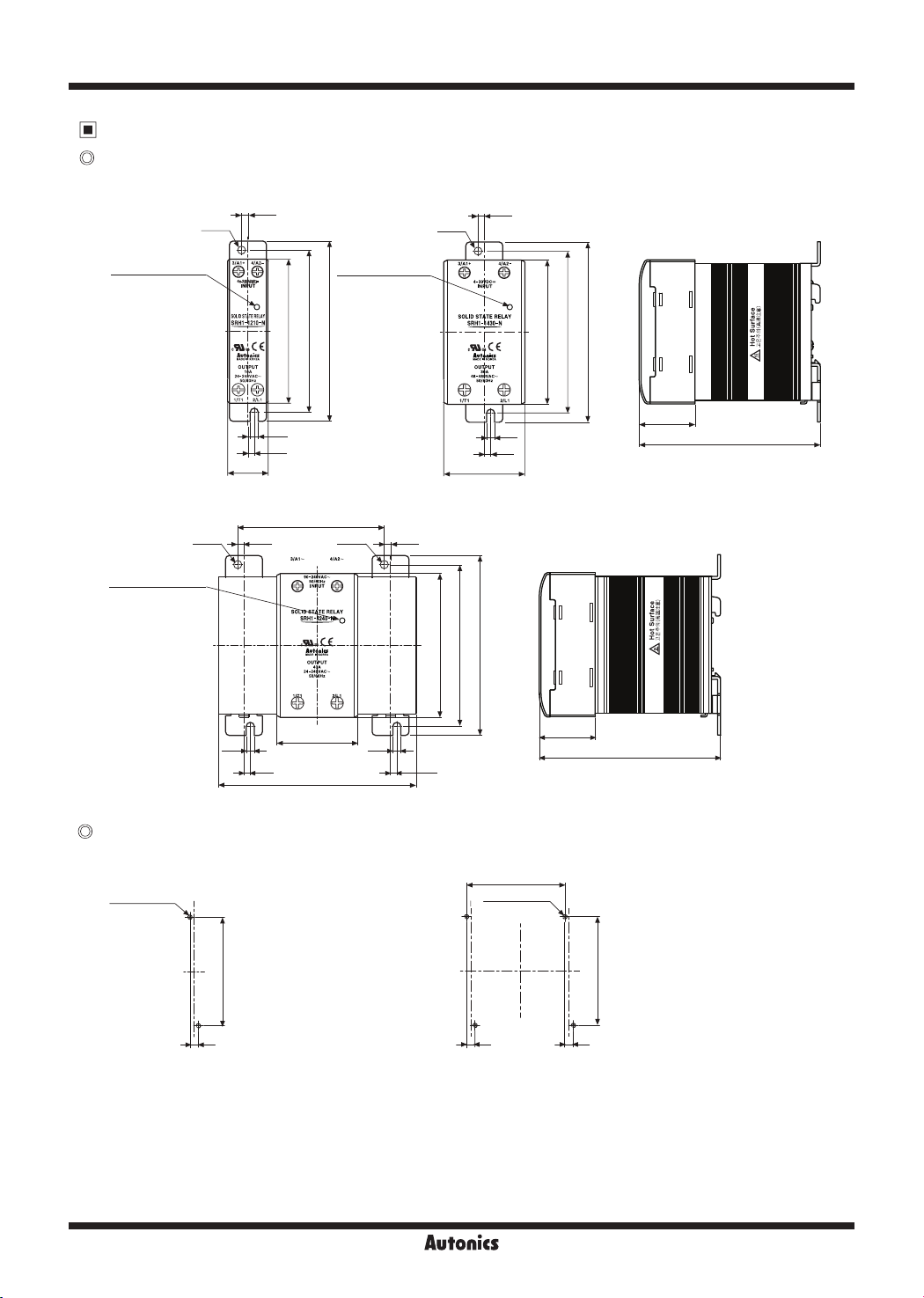
SRH1 Series
Dimensions & Mounting
Dimensions
● Rated load current 10A/15A/20A ● Rated load current 30A/40A
3.5 3.5
Ø4.5 Ø4.5
(unit: mm)
Input indicator
(green LED)
22.5
● Rated load current 60A
Ø4.5
Input indicator
(green LED)
3.5
4.5
Input indicator
(green LED)
808090
100
4.5 4.5
3.5 3.5
81.5
3.5
Ø4.5
45
110
4.5
3.5
3.5
80
90
45
100
90
100
31
100
31
100
Hole cut-out for mounting on panel
● Rated load current 10A/15A/20A/30A/40A ● Rated load current 60A
81.5
2-M4×0.7
Tap
90
7
※
Screw tightening torque for mounting: 1.8 to 2.5N.m
I-18
2-M4×0.7
Tap
7
7
90
 Loading...