

DRW1 60 913AC
Autonics
Single-Phase, Slim, Detachable Type SSR
SRC1 SERIES
I N S T R U C T I O N M A N U A L
Thank you for choosing our Autonics product.
Please read the following safety considerations before use.
Safety Considerations
Please observe all safety considerations for safe and proper product operation to avoid hazards.
※
symbol represents caution due to special circumstances in which hazards may occur.
※
~
Warning
1. Fail-safe device must be installed when using the unit with machinery that may cause
l~~i
serious injury or substantial economic loss. (e.g. nuclear power control, medical equipment,
ships, vehicles, railways, aircraft, combustion apparatus, safety equipment, crime/disaster
prevention devices, etc.)
Failure to follow this instruction may result in re, personal injury, or economic loss.
2. Install on a device panel to use.
Failure to follow this instruction may result in electric shock or re.
3. Do not connect, repair, or inspect the unit while connected to a power source.
Failure to follow this instruction may result in electric shock or re.
4. Check 'Connections' before wiring.
Failure to follow this instruction may result in re.
5. Do not disassemble or modify the unit.
Failure to follow this instruction may result in electric shock or re.
Caution
1. Use the unit within the rated specications.
Failure to follow this instruction may result in re or product damage.
2. Use dry cloth to clean the unit, and do not use water or organic solvent.
Failure to follow this instruction may result in electric shock or re.
3. Do not use the unit in the place where ammable/explosive/corrosive gas, humidity, direct
sunlight, radiant heat, vibration, impact, or salinity may be present.
Failure to follow this instruction may result in re or explosion.
4. Keep metal chip, dust, and wire residue from owing into the unit.
Failure to follow this instruction may result in re or product damage.
5. Since leakage current still ows right after turning off the power or in the output OFF status,
do not touch the load terminal.
Failure to follow this instruction may result in electric shock.
Model
Model Rated input voltage Rated load current Rated load voltage Function
SRC1-1215-N 4-30VDC
SRC1-4215-N 90-240VAC
SRC1-1220-N 4-30VDC
SRC1-4220-N 90-240VAC
SRC1-1230-N 4-30VDC
SRC1-4230-N 90-240VAC
SRC1-1420-N
SRC1-1420R-N Random turn-on
SRC1-4420-N 90-240VAC Zero cross turn-on
Dimensions
22.5
※
The above specifications are subject to change and some models may be discontinued without notice.
※
Be sure to follow cautions written in the instruction manual and the technical descriptions (catalog, homepage).
Failure to follow these instructions may result in serious injury or death.
Warning
Failure to follow these instructions may result in personal injury or product damage.
Caution
===========t---t-
15A
24-240VAC Zero cross turn-on
Zero cross turn-on
(unit: mm)
Panel
20
Panel
2-M4
Spacing
100100
※
When insta ling multiple SSRs,
please keep space between SSRs
for heat radiation.
When insta ling SSRs horizontally
(input part and output part on the
same height), please supply less
than 50% of the rated load current.
4 5
4-30VDC
Ø4 5
898998
80
Input indicator
(green)
20A
30A
20A 48-480VAC
2.4
※
Panel cut-out
Screw tightening torque
for mounting: 1.8 to 2.5N.m
33 5
Rated input voltage range 4-30VDC
Allowable input voltage range
Max. input current 18mA 18mArms (240VACrmsᜠ)
Pick-up voltage Min. 4VDC
Drop-out voltage Max. 1VDC
Turn-on
time
Turn-off time Max. 0 5 cycle of load source + 1ms Max. 2 cycle of load source + 1ms
Rated load voltage range 24-240VACrmsᜠ (50/60Hz) 48-480VACrmsᜠ (50/60Hz)
Allowable load voltage range
Rated load
current
Min. load current 0.15Arms 0 2Arms 0.5Arms 0.5Arms
Max. 1 cycle surge current (60Hz)
Max. non-repetitive surge
current (I
Peak voltage
(non-repetitive)
Leakage current (Ta=25℃) Max. 10mArms (240VACᜠ/60Hz) Max. 10mArms (480VACᜠ/60Hz)
Output on voltage drop
[Vpk] (Max. load current)
Static off state dv/dt 500V/
※
Dielectric strength (Vrms) 2500VAC 50/60Hz 1 min (input-output, input/output-case)
Insulation resistance Over 100MΩ (at 500VDC megger) (input-output, input/output-case)
Indicator Input indicator: green LED
Vibration
Shock
Environment
Input terminal connection
Output terminal connection
Input terminal xed torque 0.75 to 0.95N m
Output terminal xed torque 1 0 to 1.35N m
Approval
Weight
※
※
※
Power supply
※
Terminal type
Specications
Input
ᜡ
4-32VDC
ᜡ
ᜡ
Zero cross turn-on
Random turn-on
Output
~~-
Resistive load
※
1
(AC-51)
2
t, t=8 3ms)
1: AC-51 is utilization category at IEC60947-4-3.
General specications
Mechanical
Malfunction
Mechanical 300m/s² (approx. 30G) in each X, Y, Z direction for 3 times
Malfunction 100m/s² (approx. 30G) in each X, Y, Z direction for 3 times
Ambient
temperature
Ambient humidity 45 to 85%RH, storage: 45 to 85%RH
※
1
1: The weight includes packaging. The weight in parenthesis is for unit only.
Environment resistance is rated at no freezing or condensation.
For wiring the terminal, round terminal must be used.
Connections
(AC, DC)
Use terminals of size specied below.
<Round>
t----t------+---------+-----
a
b
ᜡ
Max. 0 5 cycle of load source + 1ms Max. 2 cycle of load source + 1ms
Max. 1ms
24-264VACrmsᜠ (50/60Hz) 48-528VACrmsᜠ (50/60Hz)
15Arms 20Arms 30Arms 20Arms
160A 250A 400A 300A
2
s 300A2s 910A2s 350A2s
130A
600V
Max. 1.6V
㎲
0.75mm amplitude at frequency of 10 to 55Hz (for 1 min) in each X, Y, Z direction for
1 hour
0.5mm amplitude at frequency of 10 to 55Hz (for 1 min) in each X, Y, Z direction for
10 min
-30 to 80℃ (in case of the rated input voltage 90-240VACᜠ: -20 to 70℃),
storage: -30 to 100
( The rated load current capacity is different depending on ambient temperature.
Refer to
Min. 1×0.5mm2 (1×AWG20), max. 1×1.5mm2 (1×AWG16) or 2×1.5mm2 (2×AWG16)
Min.1×0.75mm2 (1×AWG18), max. 1×4mm2 (1×AWG12) or 2×2.5mm2 (2×AWG14)
※
Use wires compliant with load current capacity to connect to the terminal.
ᜢ ᜧ
Approx. 119g (approx. 85g)
Input
Min.
a
Max.
b
℃
SSR Derating Curve'.)
SSR Module
4/A2- 2/L1
SRC1 seriesInput Output
3/A1+ 1/T1
Output
Min.
3 5mm
Max.
7.0mm
90-240VACrmsᜠ (50/60Hz)
85-264VACrmsᜠ (50/60Hz)
Min. 85VACrmsᜠ
Max. 10VACrms
-
-_-
1200V (Zero cross turn-on),
1000V (Random turn-on)
4.0mm
9 0mm
Load
Rapid fuse
ᜠ
Load
power source
(AC)
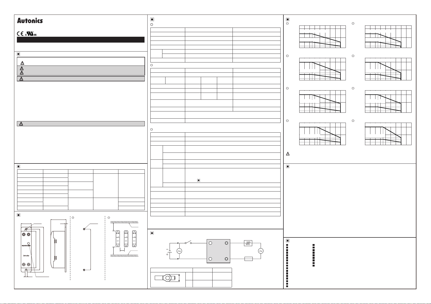
SSR Derating Curve
SRC1-1215-N
20
With heatsink 2.5℃/W
15
10
Without heatsink
6
Load current[A]
1
0
SRC1-1220-N
20
10
7.5
6
Load current[A]
1
0
SRC1-1230-N
30
9
7
Load current[A]
1
0
SRC1-1420/1420R-N
20
10
7
6
Load current[A]
2.5
0
Since effectiveness of the heat radiation is decreased when multiple SSRs are installed closely,
please supply less than 50% of the rated load current.
※
Above SSR derating curves obtained approval from the UL certication authority.
Cautions during Use
1. Follow instructions in 'Cautions during Use'. Otherwise, it may cause unexpected accidents.
2. 4-30VDC signal input should be insulated and limited voltage/current or Class 2, SELV power
supply device.
3. Attach a heat sink or install the unit in the well ventilated place.
To attach the heat sink, use Thermal Grease as below or that of equal specication.
※
Thermal Grease: GE
3. Ground to the heat sink, panel, or DIN rail. Failure to follow this instruction may result in electric shock.
4. Ground to the panel. Failure to follow this instruction may result in electric shock.
5.
While supplying power to the load or right after turning off the power of the load, do not touch the
body and heat sink. Failure to follow this instruction may result in a burn due to the high temperature.
6. In order to protect the product from the short-circuit current of the load, use rapid fuse of which I2t is
under the 1/2 of SSR I
the used rapid fuse.
7. Install dummy resistance in parallel with the load, to keep the sum of current owing in the load and
dummy resistance being over SSR minimum load current.
8. When using random turn-on model for phase control, install noise lter between the load and the
power of the load.
9. Do not use near the equipment which generates strong magnetic force or high frequency noise.
10. This unit may be used in the following environments.
Indoors (in the environment condition rated in 'Specications')
①
Altitude max. 2,000m
②
Major Products
Photoelectric Sensors Temperature Controllers
Fiber Optic Sensors Temperature/Humidity Transducers
Door Sensors SSRs/Power Controllers
Door Side Sensors Counters
Area Sensors Timers
Proximity Sensors Panel Meters
Pressure Sensors Tachometers/Pulse (Rate) Meters
Rotary Encoders Display Units
Connectors/Sockets Sensor Controllers
Switching Mode Power Supplies
Control Switches/Lamps/Buzzers
I/O Terminal Blocks & Cables
Stepper Motors/Drivers/Motion Controllers
Graphic/Logic Panels
Field Network Devices
Laser Marking System (Fiber, Co₂, Nd YAG)
Laser Welding/Cutting System
-------------
0
10 20 2530 40 50 60 70 80 90
Ambient temperature[℃]
With heatsink 2.5℃/W
Without heatsink
0
25
10 20 30 40 50 60 70 80 90
Ambient temperature[℃]
With heatsink 1.5℃/W
Without heatsink
•tlE
0
25
10 20 30 40 50 60 70 80 90
Ambient temperature[℃]
With heatsink 2.5℃/W
Without heatsink
1++:m1
0
35
10 20 30 40 50 60 70 80 90
Ambient temperature[℃]
TOSHIBA (YG6111), KANTO-KASEI (FLOIL G-600), SH NETSU (G746)
2
t. When short-circuited, replace the fuse to those of same specication with
Pollution degree 2
③
O
I
O
I
SRC1-4215-N
20
With heatsink 2.5℃/W
15
10
Without heatsink
6
Load current[A]
1
0
0
25
10 20 30 40 50 60 70 80 90
SRC1-4220-N
20
10
7.5
6
Load current[A]
1
0
0
SRC1-4230-N
30
9
7
Load current[A]
1
I i
0
0
SRC1-4420-N
20
10
7
6
Load current[A]
2.5
I L I
0
0
④ Installation category III
Ambient temperature[℃]
With heatsink 2.5
Without heatsink
10 20 30 40 50 60 70 80 90
With heatsink 1.5℃/W
Without heatsink
10 20 30 40 50 60 70 80 90
With heatsink 2.5℃/W
Without heatsink
10 20 30 40 50 60 70 80 90
/W
℃
25
Ambient temperature[℃]
i•ilB
25
Ambient temperature[℃]
35
Ambient temperature[℃]
DRW1 60 913AC
I
 Loading...