

Autonics SP Series Catalog Page

DIN Rail Mount Type Switching Mode Power Supply
Features
SP Series
SENSORS
● Compact size, high quality, cost-eective
● Universal input power
● Enables to drive various controllers
● Built-in output short over current protection circuit
● DIN rail mounting and mountable without the rail
Please read “Safety Considerations”
in the instruction manual before using.
Ordering Information
SP 03 24
Output voltage
Output power
Item
05 5VDC
12 12VDC
24 24VDC
03 3W
SP Switching Mode Power Supply
Specifications
Model SP-0305 SP-0312 SP-0324
Output power 3W
Voltage 100-240VACᜠ (permissible voltage: 85-264VAC)
Frequency 50/60Hz
Input
Eciency 67 to 74%
condi ion
Current consumption Max. 0.15A
Voltage 5VDC
ᜡ
Current 0.6A 0.25A 0.13A
Allowable voltage range Max. ±5%
Output
Ripple Max. 5%
characteristics
Voltage uctuation ratio Max. 0.5% (at 85-264VAC 100% load)
Over-current protection Min. 110%
Series / Parallel operation Not available
Indicator Output indicator: Red LED
Insulation resistance Over 100MΩ (at 500VDC megger)
Dielectric strength 2,000VAC 50/60Hz for 1 minute
Vibra ion 0.75mm amplitude at frequency of 10 to 55Hz (for 1 min) in each X, Y
Shock 300m/s² (approx. 30G) in each X, Y
Ambient temperature -10 to 50℃, storage: -20 to 70
Environ
T
-ment
Ambient humidity 35 to 85%RH
r
Unit weight Approx. 100g
※
Environment resistance is rated at no freezing of condensa ion.
I
12VDC
ᜡ
I
I
, Z direction for 3 times
℃
I
24VDC
I
I
, Z direction for 2 hours
CONTROLLERS
MOTION DEVICES
SOFTWARE
(J)
Temperature
Controllers
(K)
SSRs
(L)
Power
Controllers
(M)
Counters
(N)
Timers
(O)
Digital
Panel Meters
(P)
Indicators
(Q)
Converters
(R)
Digital
Display Units
ᜡ
(S)
Sensor
Controllers
(T)
Switching
Mode Power
Supplies
(U)
Recorders
(V)
HMIs
(W)
Panel PC
(X)
Field Network
Devices
Autonics
T-7
SP Series
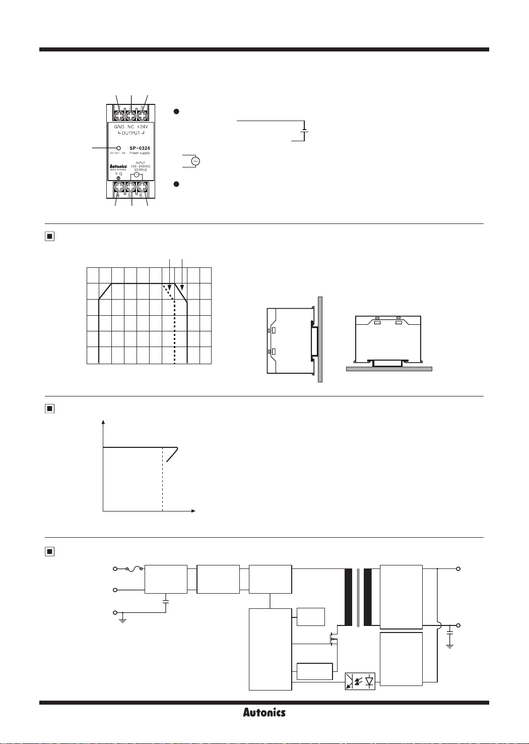
▣ Wiring Diagram/Unit Description
1 2 4
Wiring Diagram
•
1. GND terminal
2. NC terminal
A
4 5 6
Output Derating Curve by Ambient Temperature
Load
120
ratio
100
[%]
V
80
60
40
20
0
-10 0 10 20 30 40 50 60 70 80
3. Output power [+24V] terminal
4. Frame ground [F.G.] terminal
5.
Input power terminal
6.
Unit Description
•
A. Output indicator (green)
② ①
.
.
.
I\
.
.
~
.
.
.
.
.
.
.
.
.
Ambient temperature [℃]
● Be sure when installing as the efficiency is decreased by ambient
temperature.
● Refer to output feature beside when installing as the efficiency is
affected by mounting status.
-
+
e----/
D
D
'--
②①
Feature Data of Over-Current Protection
Output
voltage
[V]
● It is able to protect overcurrent by load with built in over-current protection
circuit. When the over rated current is owed, the circuit is operated (output
voltage is fallen) and it is released when the load current is under the
rated current (it is returned to the rated output voltage).
Rated
Output
current [%]
Block Diagram
Input
100-240VAC
50/60Hz
AC1(L)
AC1(N)
F.G.
ol
Input/
Noise lter
T
Inrush current
limit
Rectier
circuit
Control
circuit
Auxiliary
power
Over load
detection
Rectier
circuit
Output
voltage
detection
+
Output
-
r
T-8
Autonics
 Loading...