

Autonics SPR1 Series Instruction Manual
DRW171280AC
Autonics
Single-Phase,
LED Display Slim Power Controller
SPR1 Series
INSTRUCTION MANUAL
Please read the following safety considerations before use.
Safety Considerations
00
Please observe all safety considerations for safe and proper product operation to avoid hazards.
※
symbol represents caution due to special circumstances in which hazards may occur.
※
Warning
Caution
Warning
1. Fail-safe device must be installed when using the unit with machinery that may cause
serious injury or substantial economic loss. (e.g. nuclear power control, medical equipment,
ships, vehicles, railways, aircraft, combustion apparatus, safety equipment, crime/disaster
prevention devices, etc.)
Failure to follow this instruction may result in re, personal injury, or economic loss.
2. Install on the device panel, and ground to the bolt for grounding separately.
Failure to follow this instruction may result in electric shock or re.
3. Do not connect, repair, or inspect the unit while connected to a power source.
Failure to follow this instruction may result in electric shock or re.
4. Check 'Connections' before wiring.
Failure to follow this instruction may result in re.
5. Do not disassemble or modify the unit.
Failure to follow this instruction may result in electric shock or re.
Caution
1. Use the unit within the rated specications.
Failure to follow this instruction may result in re or product damage.
2. Use dry cloth to clean the unit, and do not use water or organic solvent.
Failure to follow this instruction may result in electric shock or re.
3. Do not use the unit in the place where ammable/explosive/corrosive gas, humidity, direct
sunlight, radiant heat, vibration, impact, or salinity may be present.
Failure to follow this instruction may result in re or explosion.
4. Keep metal chip, dust, and wire residue from owing into the unit.
Failure to follow this instruction may result in re or product damage.
5. Since leakage current still ows right after turning off the power or in the output OFF status,
do not touch the load terminal.
Failure to follow this instruction may result in electric shock.
L_
Ordering Information
00
Item
※
1: Product is not equipped with a rapid fuse inside. Install the suitable fuse for rated load current of
the model separately.
(The performance of the product is guaranteed only when using the fuse provided by us.)
※
The above specifications are subject to change and some models may be discontinued
without notice.
※
Be sure t o follow cauti ons wr itten in the i nstr ucti on manu al, use r manual, and t he
technical descriptions (catalog, homepage).
Thank you for choosing our Autonics product.
Failure to follow these instructions may result in serious injury or death.
Failure to follow these instructions may result in personal injury or product damage.
______
-
1 T FSPR 702 F
※1
I
Normal/constant current/constant
voltage/constant power control
I
I
I
I
Solid State Power Regulator
(slim type)
I
Rated load voltage
Control phase
Feedback
control
Option output
Rated load current
Fuse
N Non-fuse
F Fuse
I I I
N Normal control
I
F
I
N Alarm output
I
T Alarm+RS485 comm. output
I
25 25A
35 35A
50 50A
70 70A
'
100 100A
'
150 150A
1 110VAC
2 220VAC
3 380VAC
4 440VAC
I
1 Single-phase
J
SPR
I
Specications
00
SPR1-2
SPR1-3
Model SPR1-1
Control phase Single-phase
Rated load voltage (50/60Hz)
Power supply 100-240VACᜠ 50/60Hz
Min. load current 1A
Permissible voltage range 90 to 110% of rated voltage
Power consumption
Display method 3-digit 7-segment LED
Indicator
Control method
Applied load
Control input
Digital input (DI) RUN/STOP switching, AUTO/MAN switching, RESET
Alarm 250VACᜠ 3A, 30VDCᜡ 3A, 1c resistive load
I
Output
Communication
I
Output range
Output accuracy
Set method
I
J
Functions
Alarm
l
Cooling method
Insulation resistance Over 200MΩ (at 500VDC megger)
Dielectric strength 2,000VAC 50/60Hz for 1 min (between input terminals and power terminals)
Output leakage current Max. 10mArms
Noise immunity ±2kV the square wave noise (pulse width: 1㎲) by the noise simulator
Memory retention Approx. 10 years (when using non-volatile semiconductor memory type)
Mechanical
Vibration
Malfunction
Ambient temp. -10 to 55℃, storage: -20 to 80
Environ
ment
Ambient humi. 35 to 85%RH, storage: 35 to 85%RH
Accessory 11-pin connector
Approval
1
※
Weight
-
※
1: The weight includes packaging. The weight in parenthesis is for unit only.
※
Environment resistance is rated at no freezing or condensation.
Dimensions
00
o
Rated load current 25A/35A/50A
55
48
30 168.5
6.8
4-Ø6
21.3
J
J
181
155
197.6
□□ □□
110VAC
ᜠ
Rated load current 25A/35A/50A: max. 7VA
Rated load current 70A/100A/150A: max. 12VA
Operation indicator/Manual control indicator: green LED
Alarm indicator/output indicator/unit (V, A) indicator: red LED
Phase control: normal control mode, constant current/constant voltage/
Cycle control: xed cycle control mode, variable cycle control mode
ON/OFF control
Phase control, ON/OFF control: resistance load, inductive load
Cycle control: resistance load
Auto control: DC4-20mA, 1-5VDC
Manual control: outside adjuster (10kΩ), inside adjuster (output limit)
RS485 communication output (Modbus RTU method), max. connection: 31 units
Phase control: 0 to 98% Cycle control: 0 to 100% ON/OFF control: 0%, 100%
Normal control
Constant current feedback control
Constant voltage feedback control
Constant power feedback control
By front keys, by communication
Output limit (OUT ADJ), AUTO/MAN selection, control method selection, RESET,
SOFT START, SOFT UP/DOWN, output high/low limit, input correction, input
slope correction, monitoring (control input, load voltage/current/power/resistance,
power supply frequency, heatsink temperature)
Overcurrent alarm, overvoltage alarm, fuse break alarm, SCR error alarm,
heater break alarm, heatsink overheat alarm
Rated load current 25A/35A/50A: natural cooling
Rated load current 70A/100A/150A: forced air cooling (with the cooling fan)
0.75mm amplitude at frequency of 5 to 55Hz in each X, Y, Z direction for 2 hours
0.5mm amplitude at frequency of 5 to 55Hz in each X, Y, Z direction for 10 min
ᜢ
Rated load current 25A/35A/50A: approx. 1.6kg (approx. 1.3kg)
Rated load current 70A: approx. 1 65kg (approx. 1.35kg)
Rated load current 100A/150A: approx. 3 2kg (approx. 2 8kg)
pulse voltage (5-12VDCᜡ)
: within ±10% F.S. of rated load voltage
80°
D
ITTI
I
220VAC
ᜠ
I
constant power feedback control mode
ᜡ
: within ±3% F.S. of rated load current
: within ±3% F.S. of rated load voltage
: within ±3% F.S. of rated load power
℃
223
ITIJ
I
380VAC
I
, ON/OFF contact (no-voltage input),
J
SPR1-4
□
I
440VAC
ᜠ
I
Rated load current 70A
6.8
196
J
Rated load current 100A/150A
80
J
71
4-Ø6
40
6.8
21.3
I
238
187
252.6
80°
L
250.1
184.4
~
1//
1\
25
I
I
I
I
55
48
30
□□□□
ᜠ
4-Ø6
21.3
155
15
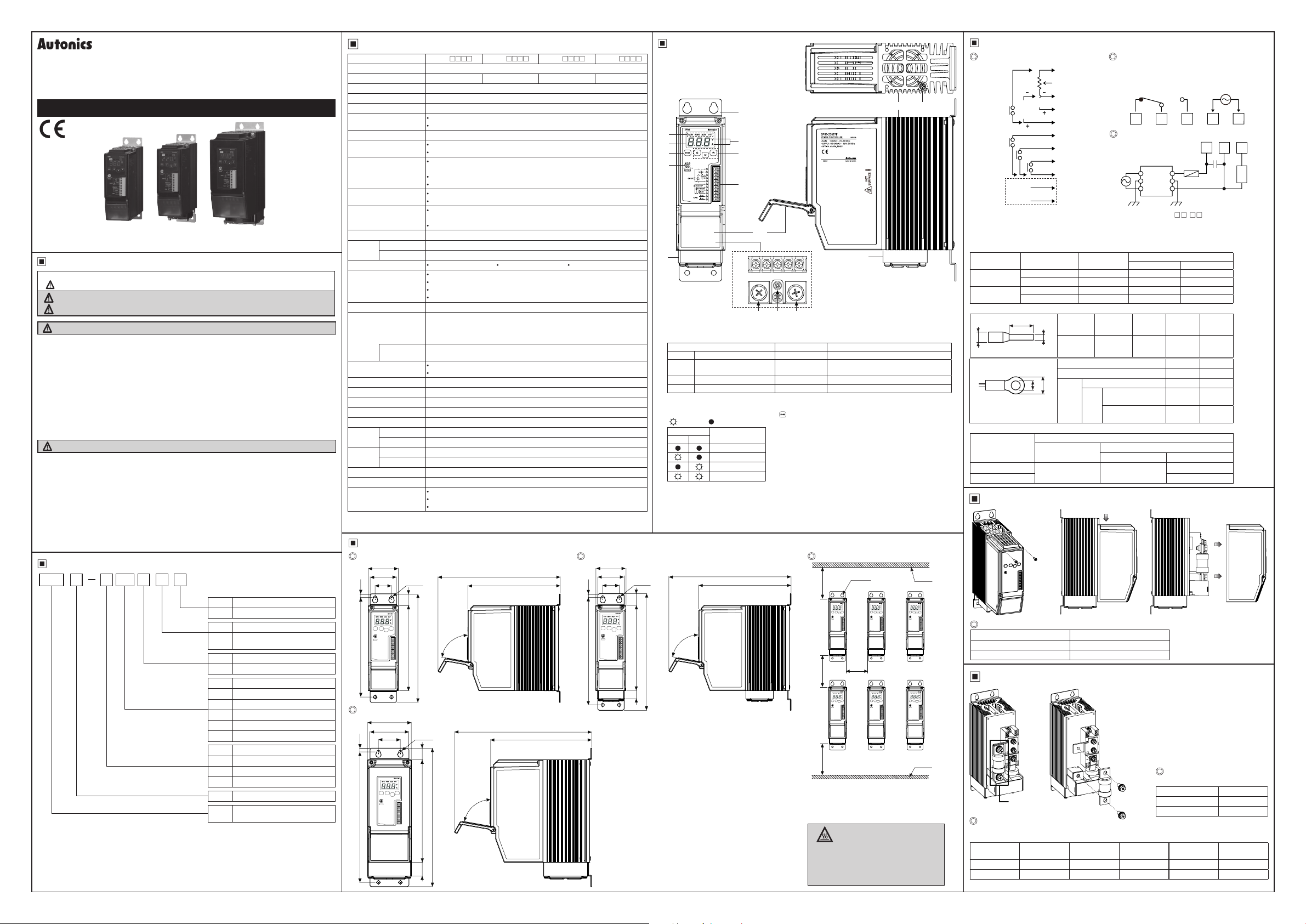
Unit Description
00
⑬
②
③
⑤
⑦
⑫
0 0
①
④
⑥
⑧
⑨
⑩
⑫
⑪
R U
S
①
Bracket
②
Indicator
Indicator Color Function
RUN Operation indicator Green LED Turns on in the RUN mode.
MAN Manual control indicator Green LED
ALM Alarm indicator Red LED Flashes in alarming status.
OUT Output indicator Red LED Turns on when load control outputs.
f=r==r:==::;::==I
③
Display par t: Displays settings of the front display [
④
Unit indicator
: Light ON/ : Light OFF)
(
Indicator
V A
• •
◊
•
◊ ◊
⑪
R, S, U load output terminals
⑫
Cooling fan: For models with the rated load current of 70A/100A/150A, a cooling fan is attached.
⑬
Heatsink
⑭
Bolt for grounding (M4)
80°
212.6
====t=====t=====E====fl
parameter and setting value in setting mode.
•
Display
Resistance, input
Voltage
•
Current
◊
Power
223
168 5
⑤
key:
⑥
Setting value adjustment key
: Enters SV setting mode and move digits.
⑦
Output limit adjuster (OUT ADJ)
: Limits output from 0 to 100%.
⑧
11-pin connector terminal
⑨
Terminal cover
⑩
Alarm output and power input terminals
Turns on when adjusting load output in
the manual control mode.
==--------==~
] parameter in RUN mode, and displays
DIS
Enters parameter group, returns to RUN mode, moves
parameters, and saves the setting value.
Spacing
4-Ø6
100100100
50
&~~
※
When installing multiple power controllers,
please keep space at least 50mm in
horizontal and 100mm in vertical between
power controllers for heat radiation.
High Temperature Caution
£.
While supplying power to the load or right after
turning off the power of the load, do not touch
the body and heatsink.
Failure to follow this instruction may result in a
burn due to the high temperature.
I
⑭
(unit: mm)
Panel
Panel
Connections
Control input/Comm. output Alarm output/power input
①
VR
rE
1-5
ll
ON/OFF
r4
VDC
L~
RUN/STOP
1
AUTO/MAN
11
(
,
___
l!C
:
※
1
RS485
i
~-
※
1: This is only for models with RS485 communication output (SPR1-
※
2: When connecting noise lter and capacitor, it is appropriate for EMC.
※
Tighten the terminal screw with the below tightening torque.
Rated load
current
25A, 35A,
50A, 70A
100A, 150A
I I I I I I
※
Use crimp terminals or terminals of size specied below.
lroB7
I I
※
Connect the specied wire as the rated load current.
Rated load current
25A/35A/50A/70A
100A/150A AWG 4 to 2/0
I I I I
Rated load current Specication of bolts
25A, 35A, 50A, 70A M3
100A, 150A M4
Recommended fuse specifications
0
For replacing the fuse, please use the recommended fuse which has the below specications.
(manufacture: BUSSMANN)
Rated load
current
25A 50FE 50A 80ET 100A FWH-150B
35A 63ET 70A 100FE 150A FWH-200B
I I I I I I
※
The performance of the product is guaranteed only when using the fuse provided by us.
I
---- ------ -----
CAP : Rated load voltage 110VAC-220VAC → 1uF/250VAC
: Rated load voltage 380VAC-440VAC → 0.47uF/500VAC
Specication
Screw M3 M3 M6
Tightening torque 0.5N.m 0 5N.m 5 5 to 6.0N m
Screw M3 M3 M8
Tightening torque 0.5N.m 0 5N.m 6 5 to 7.0N m
a
c
<Crimp terminal>
~
<Round>
Removing the Case
Specification of case fixing bolts
Replacement of Fuse
Fuse
Model
②
③
4-20mA
~
④
⑤
+
⑥
⑦
'
⑧
RESET
⑨
:
A(+)
------+
:
⑩
B(-)
______...,
!
⑪
--·
Alarm output/
power input
Terminal
type
b
Input
(11-pin)
I I I I I I
Terminal type a b
Alarm output/power input Min. 3.0 Max. 6.0
a
b
I I I I I I
Load
output
Wire specication
Alarm output/
power input
AWG 18 to 14 AWG 18 to 14
Case
xing
bolts
Terminal
number
1 to 11 6 to 7 Max. 1 5 Max. 3.5
S Min. 3.0 Max. 8.0
Rated load current
25A/35A/50A/70A
R, U
Rated load current
100A/150A
Load output
S R, U
·.
•.
Rated load
current
Alarm Output
(250VAC 3A 1c)
(30VDC 3A 1c)
Resistive Load
N.C. N.O. LCOM N
l?°lr87
1 2 3 4 5
□ □
Load output
Noise lter
Load output
S R, U
a b c
①
-~
Fuse
xing bolts
·
..
--
~
Model
□ □
※
2
Rapid fuse
□□
Min. 6.0 Max. 16 0
Min. 8.0 Max. 26 0
AWG 13 to 4
Specification of
0
fuse fixing bolts
Rated load current Spec. of bolts
25A, 35A, 50A, 70A M6
100A, 150A M8
Rated load
current
T ).
□□
100-240VAC
50/60Hz
□
R S U
CAP
※
2
(unit: mm)
②
I
Model
Load
I
Parameter Group
~
※
Hold the key in RUN mode to enter into parameter group.
~
※
In parameter setting group, press the key to move to other parameter in the group.
※
Press the key once after changing the setting value, to save the setting value and move to the
~
next parameter.
※
When entering to the parameter, press the key to move digit, , keys to change the setting
value.
※
If there is no key input for 30 sec while setting SV or the parameters, the new settings are ignored, and
the unit will return to RUN mode with previous settings.
Hold the key for 3 sec to save the setting value and return to RUN mode after changing the
※
~
setting value.
~
I
Monitoring group Parameter 1 group [
:
~
~
RUN mode
I~
I I I I
~@§]
2 sec 4 sec
] Parameter 2 group [
PA1
I
~
PA2
]
Monitoring group
Display Measuring range Description Unit
0 to 100 Displays the present control input as percentage. %
IN
※
1
0 to rated voltage range Displays the present load voltage. V
L V
※
1
0 to rated current range Displays the present load current. A
L A
※
1
0 to rated power range Displays the present load power. kW
L W
※
1
0 to 100
L R
0 to 100 Displays the present temperature of heatsink.
TMP
50, 60 Displays the present frequency of power supply. Hz
FRQ
Displays the present resistance as percentage
compared to the set resistance of full load auto
recognition.
Factory
default
-
-
-
-
%
-
-
℃
-
Load Output Formula
Type Input Display Formula
Current DC4-20mA
Auto
control
Voltage 1-5VDC
(AUTO)
RS485 communication
Output
limit
Inside adjuster
Outside adjuster
Inside/outside
adjuster
Manual
control
(MAN)
Comprehensive Device Management Program [DAQMaster]
DAQMaster is a comprehensive device management software for setting parameters and
monitoring processes.
Item Minimum specications
System BM PC compatible computer with Pentium Ⅲ or above
Operations Windows 98/NT/XP/Vista/7/8/10
Memory 256MB+
Hard disk 1GB+ of available hard disk space
VGA Resolution: 1024×768 or higher
Others RS232C serial port (9-pin), USB port
User Manual for Communication
For the detail information and instructions, please refer to user manual for communication, and be sure
to follow cautions written in the technical descriptions (catalog, homepage).
RS485 Communication Output
※
Applicable for models with RS485 communication output through option output (SPR1Please refer to '
Ordering Information'.
1. Communication Specifications
Comm. protocol Modbus RTU
Connection method RS485
Application standard
Compliance with EIA RS485 Comm. response time
Max. connections 31 units (address: 1 to 99) Start bit 1-bit (xed)
Synchronization method
Asynchronous Data bit 8-bit (xed)
Comm. method Two-wire half duplex Parity bit None, Even, Odd
Comm. distance Max. 800m Stop bit 1-bit, 2-bit
2. Application of system organization
RS232C/
USB/Wi-Fi
I
Comm.
•=
Computer
※
t is recommended to use Autonics communication converter; SCM-WF48 (Wi-Fi to RS485 USB wireless
communication converter, sold separately), SCM-US48I (USB to RS485 converter, sold separately),
SCM-38I (RS232C to RS485 converter, sold separately). Please use twisted pair wire, which is suitable
for RS485 communication, for SCM-WF48, SCM-US48I and SCM-38I.
converter
RS485
:~\~
,---i,,
B(-)
I
I
ON OFF
\
tJ;
...
____
A(+)
'
...
INT
MAN
,
420
Load output [%]
= Control input [%] × Output slope (
1 5
COM
Load output [%] = RS485 [%]
I R
Load output [%] = Inside adjuster [%]
E R
Load output [%] = Outside adjuster [%]
Load output [%]
E I
= Inside adjuster [%] × Outside adjuster [%]
Comm. speed
2400, 4800, 9600, 19200,
38400 bps
5 to 99ms (default: 20ms)
Terminating
resistance
(100 to 120Ω)
I I
A(+)
DEVICE
RS485
#1
A(+) A(+)B(-) B(-) B(-)
...
RS485
DEVICE
#2
RS485
DEVICE
#30
) [%]
SLP
T
□□ □□
B(-)
RS485
DEVICE
#31
A(+)
).
(Q)
Parameter 1 group [
Display Setting range Description Unit
0 to 100 Set SOFT START time. sec
S T
0 to 100 Set SOFT UP time. sec
U T
0 to 100 Set SOFT DOWN time. sec
D T
L L
~
0 ≤
≤
L L
H L
※
SLP
(Q)
Parameter 2 group [
Display Setting range Description Unit
:
※
INT
C M
※
MAN
※
INB
※
SPN
DIS
※
OCV
※
OCT
※
OVV
※
OVT
※
F L
※
HBV
※
ADR
※
BPS
※
PRT
※
STP
※
RwT
※
CmW
LOC
INI NO
※
Displayed only for feedback control models.
1:
※
2: Set the below parameters available depends on the control input.
Type Input Display
I
H L
2
0 to 100
DC4-20mA
420
1-5VDC
1 5
2
5-12VDC
512
ON/OFF contact
ONF
RS485 comm.
COM
Phase control
PA
- Normal
Phase control
※
1
- Constant voltage
V F
feedback
Phase control
※
1
- Constant current
C F
feedback
Phase control
※
1
- Constant power
W
F
feedback
Cycle control
F
C
- Fixed cycle
Cycle control
V C
- Variable cycle
ON/OFF control
ONF
Inside adjuster
I R
Outside adjuster
E R
2
Inside/Outside
E I
adjuster
2
-99 to 99
2
-99 to 99
Resistance and
IN
input
※
1
Load voltage
L V
※
1
Load current
L A
※
1
Load power
L W
1
0 to 120 Set the overcurrent alarm value. %
1
0 to 100 Set the overcurrent alarm delay time. sec
1
0 to 120 Set the overvoltage alarm value. %
1
0 to 100 Set the overvoltage alarm delay time. sec
1
/
OFF
ON
1
/ 10 to 100 Set the heater break alarm value. %
OFF
3
01 to 99 Assign the unique address when communicating.
3
24, 48, 96, 192, 384
3
/
/
NON
EVE
ODD
3
1, 2
3
5 to 99
Enable
EnA
3
Disable
DsA
Unlock
OFF
lock
lock
LC2 PA2
/
YES
Current DC4-20mA
Voltage 1-5VDC
Auto
control
pulse voltage 5-12VDC
(AUTO)
No-voltage ON/OFF contact
RS485 communication
Manual
control
Output limit
(MAN)
※
3: Displayed only for models with RS485 comm. output.
]
PA1
≤ 100
Set the output low-limit value. %
Set the output high-limit value. %
In case of auto control (AUTO), set the output slop
limit proportional to control input for limit load power.
]
PA2
Set the control input specication.
Set the control method.
In case of manual control (MAN), set the output limit
method.
Set the compensated input value for the offset
between the actual input value and the measured
input value.
Set the compensated input slope value between the
actual input value 100% and the measured input value
100%.
Set the desired value to be displayed at the front
display part.
resistance value recognized automatically as the initial
set when the function is ON.
Set the speed of data transmission. Multiply by 100 to
read the set value. (e.g.: 96=9600bps)
A parity bit is a data communication method that adds
an additional bit to each character in transmitted data
as an indicator used to verify data loss and corruption.
Set the number of bits to mark the end of a transmitted
data string.
Set standby time to prevent communication errors
when communicating with a slow master device (PC,
PLC, etc.).
Enable or disable the setting of parameters stored in
memory via communication from the master system
(PC, PLC, etc.). Reading the set value in parameter is
always possible.
The parameter group settings can not be changed
when the function is ON.
If set the parameter to YES, reset all parameters to
default.
Hold the
reset parameter.
Inside adjuster
Outside adjuster
Inside/outside
adjuster
t executes 100% control output for 3 sec and the load
, keys for 5 sec, to enter parameter
~~§I
INT
MAN
Input
correction
[
INB
420
1 5
512
ONF
COM
I R
f---
E R
~
E I
Input slope
correction
]
[
SPN
0 0
0 0
X X
X X
X X
X X
Functions
Factory
default
3
3
3
0
100
%
100
Output limit (OUT ADJ)
This function will be [Control input (%) × OUT ADJ (%) =
Output] and it controls the power supplied into the load.
Although control input is 100% (5V or 20mA), the output
is the 50% which is proportioned with OUT ADJ.
※
This function can not be used for ON/OFF control method.
Output high limit/low limit value [
This function is to limit output range to protect load.
H-L/L-L
[%]
Output
]
[%]
Output
Control input [%]
' ' '
Setting value 100%
Setting value 50%
Output high limit value [H-]
80%
:Lldf:})_i:
20 -
Factory
default
SOFT START [
-
-
-
%
%
When the power is supplied, this function is able to
420
protect the load when it controls load (molybdan,
white gold, infrared lamp) with inrush current or the
width of rising temperature in big (SV is big).
SOFT START set time (T) is the required time that
output reaches to 100%, and it is differentiated by
OUT ADJ set value.
※
This function can not be used for ON/OFF control method.
SOFT UP/DOWN [
Unlike SOFT START which operates only once at
supplying power, this function protects load from the
PA
inrush current in the RUN mode. When reached to
the target output value, operation stops.
※
This function can not be used for ON/OFF control method.
Input correction [
It compensates the offset between actual input value
and measured input value.
I R
E.g.) When input monitoring value is 5% at 4mA in
DC4-20mA control input, setting
)0
)0
calibrates the input monitoring value to 0%.
Input slope correction [
It compensates the gain of the measured 100% input
for actual 100% input value.
Calibrated monitoring value=Monitoring value+
-
-
-
bps
-
bit
E.g.) When the input monitoring value is 99% at 4mA in
IN
120
5
120
5
OFF
10
01
96
NON
2
DC4-20mA control input,
the input monitoring value to 100%.
RUN/STOP switching
RUN/STOP status of the power controller can be switched with the external
RUN/STOP contact.
In the RUN mode, the operation indicator on the front turns on.
AUTO/MANUAL selection
Operation mode (auto control/manual control) of the power controller can be
selected with the external AUTO/MAN contact.
In the manual control mode, the manual control indicator on the front turns on.
RESET
In the event of system anomalies and alarms, RESET input restarts the
power controller.(Parameters are not initialized.)
Or, hold the
Alarm
Type
ms
20
SCR error alarm
Overcurrent alarm
f-----------+---+------1
-
-
-
Output
slope
]
[
SLP
]
Monitoring
value
[ IN]
0
0
0
The last
control
0
input
X
value
0 to 100%
X
Heatsink overheat
EnA
alarm
Overvoltage alarm
f-----------+---+------io
Fuse break alarm
OFFLC1 PA1
Heater break alarm
※
1: This is only for feedback control models.
※
NO
When multiple alarms occur at the same time, the highest priority error message will be displayed
based on priority.
1) SCR error alarm
Even though output is 0%, if the current of 10% or more of the rated load current ows for over 3 sec
continuously, SCR error alarm occurs.
2) Overcurrent alarm
This function protects the load from overcurrent.
If the current ows over the overcurrent alarm setting value [
overcurrent alarm occurs.
3) Heatsink overheat alarm
When the temperature of a heatsink is over 85℃, heatsink overheat alarm occurs.
4) Overvoltage alarm
This function protects the load from overvoltage.
If the current ows over the overvoltage alarm setting value [
overvoltage alarm occurs.
5) Heater break alarm
Comparing the full load resistance value and the current load resistance value, if the current load
resistivity is maintained under the setting value [
occurs. This alarm operates when control output is over 10% and load current is over 10% of the rated
current. Output does not stop and operates normally.
Current load resistivity(%) =
S-T
]
U-T/D-T
INB
]
setting SP to calibrates
, keys
for 2 sec, to operates RESET.
Display
Error
※
1
※
※
Priority
SCR
1
O C
TEM
1
O V
FUS
※
1
H B
Current load resistance value
]
A SOFT START function nished.
B SOFT UP function nished.
C SOFT DOWN function nished.
INB
to 5
SPN
]
Monitoring value
Operation
Alarm Output
1
2
.
4
5
3
6
Full load resistance value
×
SP
SP
100-
Error messege
ashes.
Alarm indicator
(ALM) ashes.
Alarm output
turns ON
HBV
] for over 3 sec continuously, heater break alarm
Output stops.
Continues operation
---1---r--
~
-~----+---------
0 25 50
[%]
When output applied to load is 100%,
100
Output
When output app ied to load is 50%,
50
0
SOFT START set time
[%]
100
Output
50
0
SOFT START set time
100
[%]
60
40
Measured input signal
0
Actual input signal [%]
100
[%]
60
40
Measured input signal
Actual input signal [%]
(SCR OFF)
] and setting delay time [
OCV
] and setting delay time [
OVV
100
×
Output low limit value [-]
75
100
Control input [%]
Time
SOFT UP set ime
Time
1008075
502025
1008075
5020250
RUN/STOP
I
ON/OFF
AUTO/MANI~
I
ON/OFF
RESET
ON
I
Clear alarm
Re-supply the power
RESET
Switch to STOP mode
Automatically cleared
when returning within
the setting range
10%
SOFT DOWN set time
Actual input signal (%)
Input corrected signal (%)
Actual input signal (%)
Input corrected signal (%)
I~®
<4®
(j) I
<4®
I~®
<4®
],
OCT
],
OVT
I
I
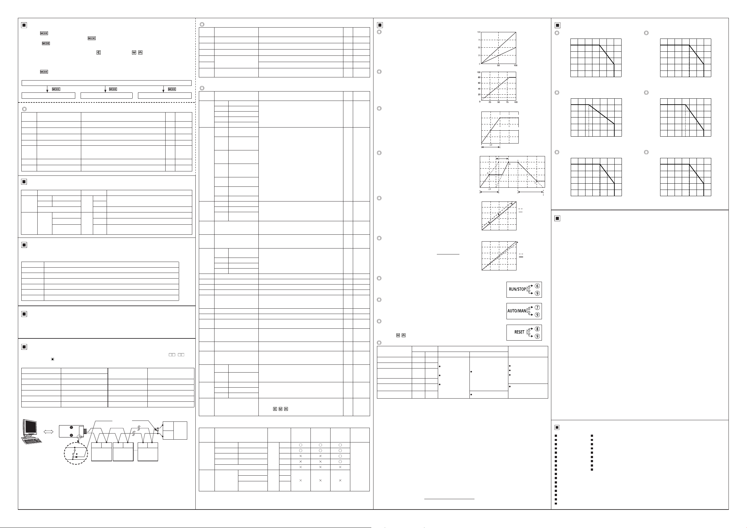
Derating Curve
Rated load current 25A
25
20
15
Load current [A]
10
5
0010 20 30 40 50 60 70
I'\.
\
Ambient temperature [℃]
Rated load current 50A
50
40
30
Load current [A]
20
10
0010
20 30
40 50 60 70
25
Ambient temperature [℃]
Rated load current 100A
100
80
60
Load current [A]
40
20
0010 20 30 40 50 60 70
Cautions during Use
\.
\
Ambient temperature [℃]
Rated load current 35A
35
28
21
Load current [A]
14
7
0010 20 30 40 50 60 70
I'\.
Ambient temperature [℃]
Rated load current 70A
70
56
42
Load current [A]
28
14
0010 20
I\.
30 40
50 60 70
35
Ambient temperature [℃]
Rated load current 150A
150
120
90
Load current [A]
60
30
0010 20 30 40 50 60 70
I\.
Ambient temperature [℃]
\
\
1. Follow instructions in 'Cautions during Use'. Otherwise, it may cause unexpected accidents.
2. Use the product, after 3 sec of supplying power.
3. Before use, set the mode and function according to the specification. Especially, be cautious that the
product does not operate when OUT ADJ. is set to 0%. Since changing the mode/parameter during
operation may result in malfunction, set the mode and function after disconnecting load output.
4. Re-supply the power to the unit after the unit is discharged completely.
Failure to follow this instruction may result in malfunction.
5. To ensure the reliability of the product, install the product on the panel or metal surface vertically to
the ground.
6. Install the unit in the well ventilated place.
7. While supplying power to the load or right after turning off the power of the load, do not touch
the body and heat sink. Failure to follow this instruction may result in a burn due to the high
temperature.
8. Install a power switch or circuit breaker in the easily accessible place for supplying or disconnecting
the power.
9. Do not wire to terminals which are not used.
10. Since inter element can be damaged when using with coil load, inductive load, etc., the inrush
current must be under the rated load current.
11. Do not use near the equipment which generates strong magnetic force or high frequency noise.
12. This unit may be used in the following environments.
①
Indoors (in the environment condition rated in 'Specifications')
②
Altitude max. 2,000m
③
Pollution degree 2
④
Installation category III
Major Products
00
Photoelectric Sensors Temperature Controllers
Fiber Optic Sensors Temperature/Humidity Transducers
Door Sensors SSRs/Power Controllers
Door Side Sensors Counters
Area Sensors Timers
Proximity Sensors Panel Meters
Pressure Sensors Tachometer/Pulse (Rate) Meters
Rotary Encoders Display Units
Connector/Sockets Sensor Controllers
Switching Mode Power Supplies
Control Switches/Lamps/Buzzers
I/O Terminal Blocks & Cables
Stepper Motors/Drivers/Motion Controllers
Graphic/Logic Panels
Field Network Devices
Laser Marking System (Fiber, CO₂, Nd: YAG)
Laser Welding/Cutting System
■
■
■
■
■
■
■
■
■
DRW171280AC
 Loading...