

Autonics SPR1 Series, SPR3 Series Catalog Page
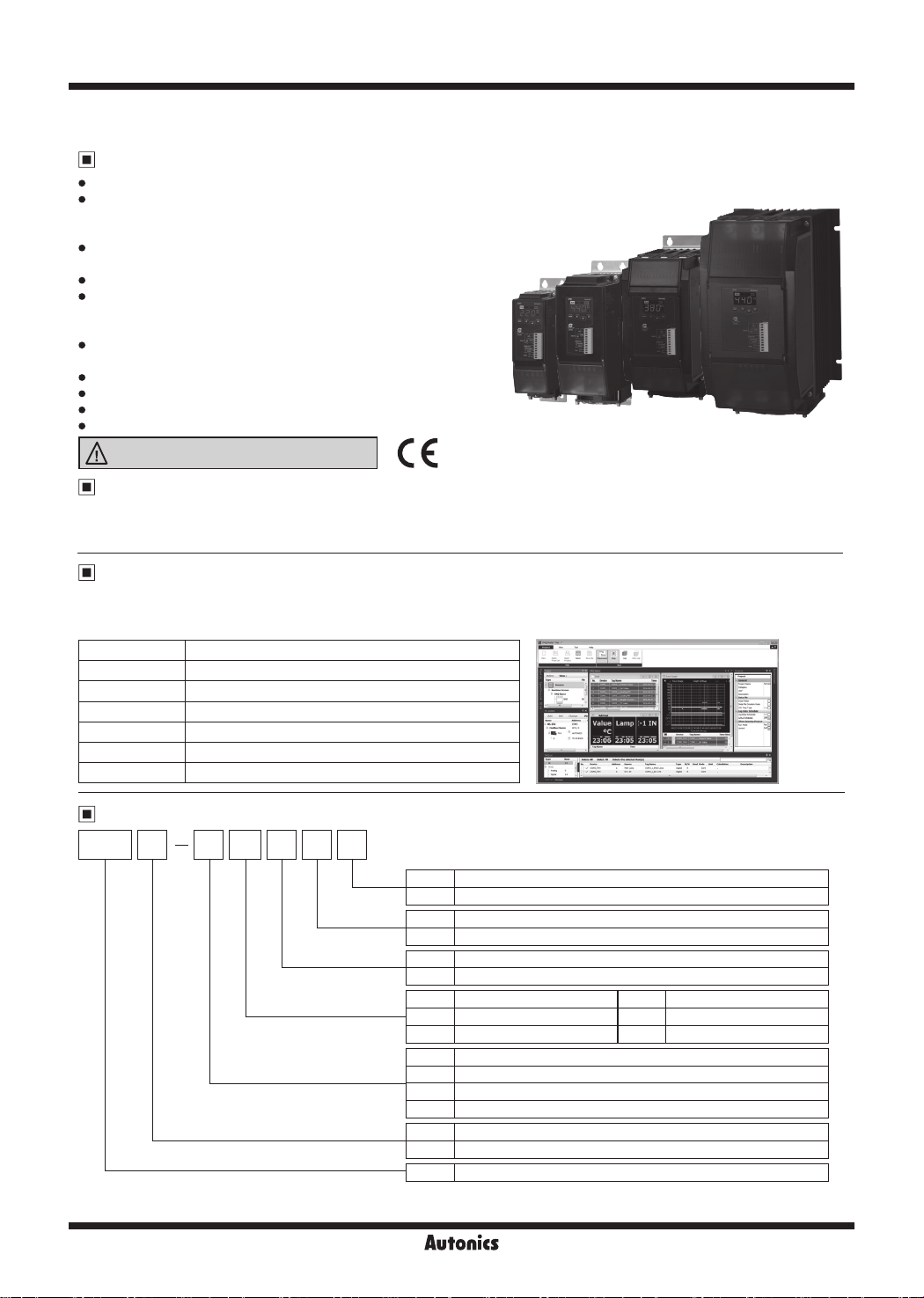
SPR1/SPR3 Series
Single-Phase/3-Phase, LED Display, Slim, Power Controller
Features
Rene and slim body design
LED display for real time monitoring (control input, load voltage,
load current, load power, load resistance and heatsink temperature)
and checking parameter settings
Stable control by feedback control
(constantcurrent/constant voltage/constant power control)
Communication output model available: RS485 (Modbus RTU method)
Convenient parameter settings via PC (RS485 communication)
: Free download the comprehensive device management program
(DAQMaster)
Various alarm functions (alarm output)
: overcurrent, overvoltage, heatsink overheat, fuse break, SCR error
Easy installation of the bracket
Simple fuse replacement structure for easy maintenance
Interphase insulating barrier included - SPR series
Highly reliable SCR (IXYS) element
Please read “Safety Considerations”
in the instruction manual before using.
Manual
● For the detail information and instructions, please refer to user manual for communication, and be sure to follow cautions written in the
technical descriptions (catalog, website). Visit our website (www.autonics.com) to download manuals.
● User manual for communication manual describes for RS485 communication (Modbus RTU protocol) and parameter address map data.
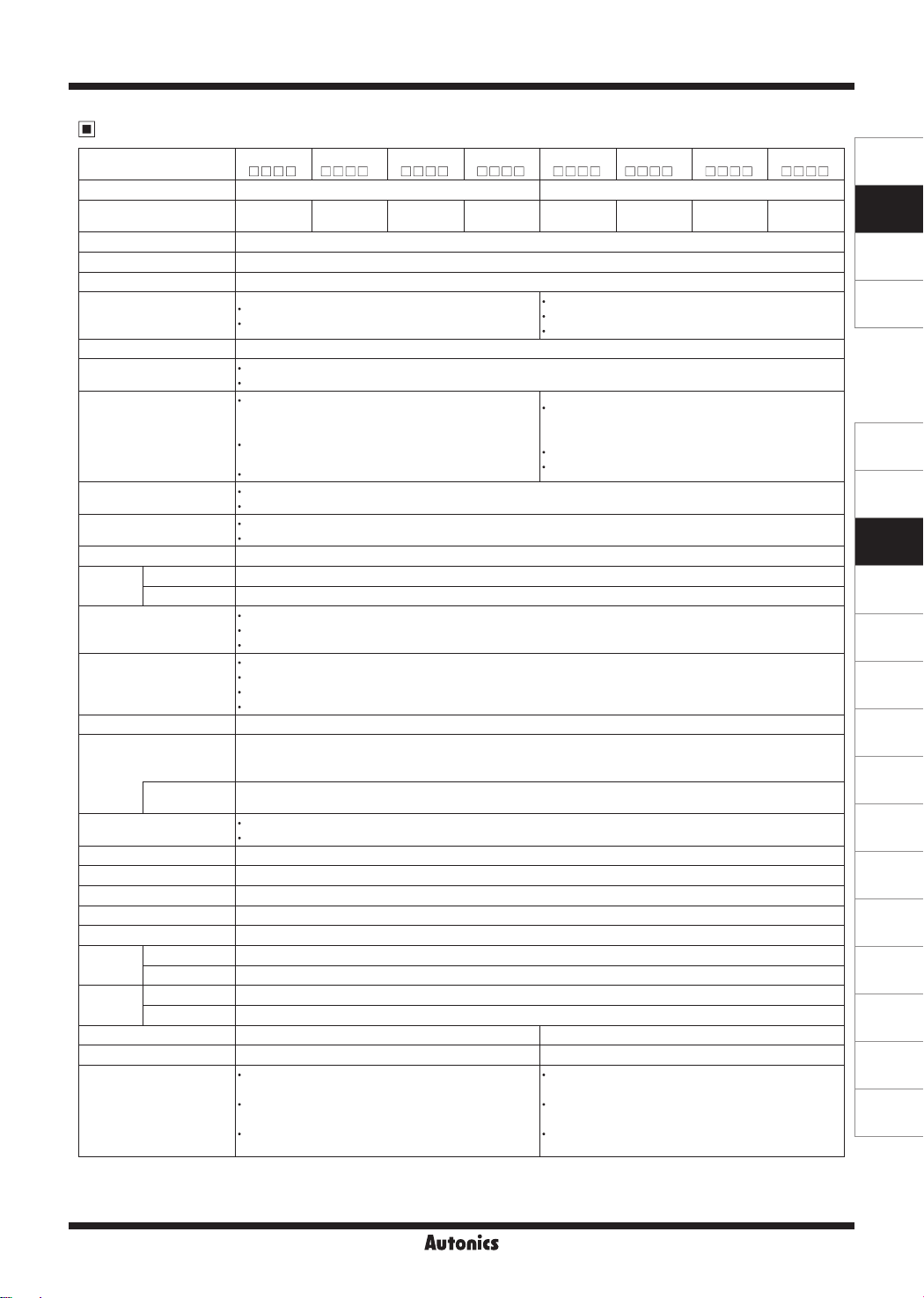
Comprehensive Device Management Program
● DAQMaster is a comprehensive device management software for setting parameters and monitoring processes.
● Visit our website (www.autonics.com) to download user manual and comprehensive device management program.
Item Minimum specications
System IBM PC compatible computer with Pentium Ⅲ or above
Operations Windows 98/NT/XP/Vista/7/8/10
Memory 256MB+
Hard disk 1GB+ of available hard disk space
VGA Resolution: 1024×768 or higher
Others RS232C serial port (9-pin), USB port
(DAQMaster)
< DAQMaster screen >< Computer specication for using software >
Ordering Information
1 T FSPR 702 F
※
Fuse
Feedback
control
Option output
Rated load current
Rated load voltage
Control phase
Item
※
1: Product is not equipped with a rapid fuse inside. Install the suitable fuse for rated load current of the model separately.
(The performance of the product is guaranteed only when using the fuse provided by us.)
Non-fuse
N
Fuse
F
N
Normal control
F
Normal/constant current/constant voltage/constant power control
N
Alarm output
T
Alarm+RS485 comm. output
25
25A 70 70A
35
35A 100 100A
50
50A 150 150A
1
110VAC
2
220VAC
3
380VAC
4
440VAC
1
Single-phase
3
3-phase
SPR
Solid State Power Regulator (slim type)
L-12 L-13
1
Single-Phase/3-Phase, LED Display, Slim, Power Controller
Specications
Model
SPR1
-1
Control phase Single-phase 3-phase
Rated load voltage
(50/60Hz)
110VACᜠ220VACᜠ380VACᜠ440VACᜠ110VACᜠ220VACᜠ380VACᜠ440VAC
Power supply 100-240VACᜠ 50/60Hz
Min. load current 1A
Permissible voltage range 90 to 110% of rated voltage
Power consumption
Rated load current 25A/35A/50A: max. 7VA
Rated load current 70A/100A/150A: max. 12VA
Display method 3-digit 7-segment LED
Indicator
Operation indicator/Manual control indicator: green LED
Alarm indicator/output indicator/unit (V, A) indicator: red LED
Phase control: normal control mode, constant current/
Control method
Cycle control: xed cycle control mode,
ON/OFF control
Applied load
Control input
Phase control, ON/OFF control: resistance load, inductive load
Cycle control: resistance load
Auto control: DC4-20mA, 1-5VDCᜡ, ON/OFF contact (no-voltage input), pulse voltage (5-12VDCᜡ)
Manual control: outside adjuster (10kΩ), inside adjuster (output limit)
Digital input (DI) RUN/STOP switching, AUTO/MAN switching, RESET
Output
Alarm 250VACᜠ 3A, 30VDCᜡ 3A, 1c resistive load
Communication RS485 communication output (Modbus RTU method), max. connection: 31 units
Phase control: 0 to 98%
Output range
Cycle control: 0 to 100%
ON/OFF control: 0%, 100%
Normal control: within ±10% F.S. of rated load voltage
Output accuracy
Constant current feedback control: within ±3% F.S. of rated load current
Constant voltage feedback control: within ±3% F.S. of rated load voltage
Constant power feedback control: within ±3% F.S. of rated load power
Set method By front keys, by communication
Output limit (OUT ADJ), AUTO/MAN selection, control method selection, RESET, SOFT START, SOFT UP/DOWN,
output high/low limit, input correction, input slope correction, monitoring (control input, load voltage/current/power/
Functions
Alarm
Cooling method
resistance, power supply frequency, heatsink temperature)
Overcurrent alarm, overvoltage alarm, fuse break alarm, SCR error alarm, heater break alarm,
heatsink overheat alarm
Rated load current 25A/35A/50A: natural cooling
Rated load current 70A/100A/150A: forced air cooling (with the cooling fan)
Insulation resistance Over 200MΩ (at 500VDC megger)
Dielectric strength 2,000VAC 50/60Hz for 1 min (between input terminals and power terminals)
Output leakage current Max. 10mArms
Noise immunity ±2kV the square wave noise (pulse width: 1㎲) by the noise simulator
Memory retention Approx. 10 years (when using non-volatile semiconductor memory type)
Vibration
Environment
Mechanical 0.75mm amplitude at frequency of 5 to 55Hz in each X, Y, Z direction for 2 hours
Malfunction 0.5mm amplitude at frequency of 5 to 55Hz in each X, Y, Z direction for 10 min
Ambient temp. -10 to 55℃, storage: -20 to 80
Ambient humi. 35 to 85%RH, storage: 35 to 85%RH
Accessory 11-pin connector 11-pin connector, insulating barrier: 4
Approval
ᜢ ᜢ
Rated load current 25A/35A/50A
: approx. 1.6kg (approx. 1.3kg)
Weight
※
1
Rated load current 70A
: approx. 1.65kg (approx. 1.35kg)
Rated load current 100A/150A
: approx. 3.2kg (approx. 2.8kg)
※
1: The weight includes packaging. The weight in parenthesis is for unit only.
※
Environment resistance is rated at no freezing or condensation.
SPR12
SPR1
-3
SPR1
-4
constant voltage/constant power
feedback control mode
variable cycle control mode
℃
SPR3
-1
SPR32
SPR3
-3
SPR3
-4
ᜠ
Rated load current 25A/35A/50A: max. 14VA
Rated load current 70A: max. 22VA
Rated load current 100A/150A: max. 32VA
Phase control: normal control mode, constant current/
constant voltage/constant power
feedback control mode
Cycle control: xed cycle control mode
ON/OFF control
Rated load current 25A/35A/50A
: approx. 4.9kg (approx. 4.1kg)
Rated load current 70A
: approx. 5kg (approx. 4.2kg)
Rated load current 100A/150A
: approx. 9.7kg (approx. 8.7kg)
SENSORS
CONTROLLERS
MOTION DEVICES
SOFTWARE
(J)
Temperature
Controllers
(K)
SSRs
(L)
Power
Controllers
(M)
Counters
(N)
Timers
(O)
Digital
Panel Meters
(P)
Indicators
(Q)
Converters
(R)
Digital
Display Units
(S)
Sensor
Controllers
(T)
Switching
Mode Power
Supplies
(U)
Recorders
(V)
HMIs
(W)
Panel PC
(X)
Field Network
Devices
SPR1/SPR3 Series
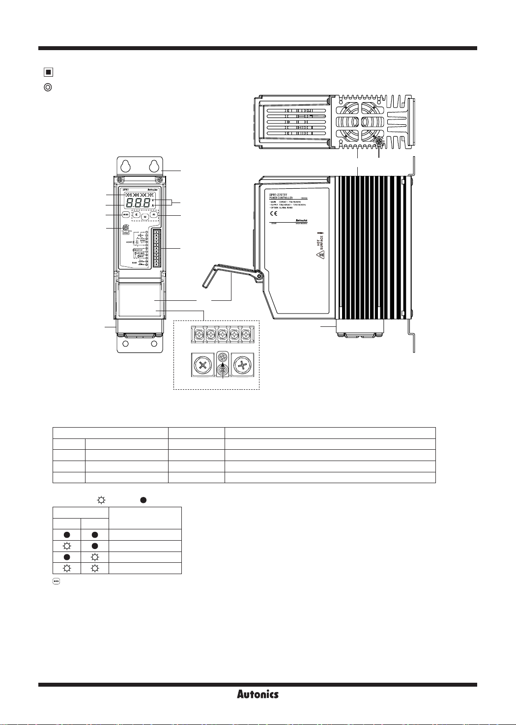
Unit Description
SPR1 Series
①
⑭
⑬
②
③
⑤
④
⑥
⑦
⑧
⑨
⑬
⑩
⑫
⑪
S
R U
①
Bracket
②
Indicator
Indicator Color Function
RUN Operation indicator Green LED Turns on in the RUN mode.
MAN Manual control indicator Green LED Turns on when adjusting load output in the manual control mode.
ALM Alarm indicator Red LED Flashes in alarming status.
OUT Output indicator Red LED Turns on when load control outputs.
③
Display part: Displays settings of the front display [
④
Unit indicator ( : Light ON/ : Light OFF)
Indicator
V A
⑤
key: Enters parameter group, returns to RUN mode, moves parameters, and saves the setting value.
⑥
Setting value adjustment key: Enters SV setting mode and move digits.
⑦
Output limit adjuster (OUT ADJ): Limits output from 0 to 100%.
⑧
11-pin connector terminal
⑨
Terminal cover
⑩
Alarm output and power input terminals
⑪
R, S, U load output terminals
⑫
Cooling fan: For models with the rated load current of 70A/100A/150A, a cooling fan is attached.
⑬
Heatsink
⑭
Bolt for grounding (M4)
Display
Resistance, load
Voltage
Current
Power
DIS
] parameter in RUN mode, and displays parameter and setting value in setting mode.
L-14 L-15
Single-Phase/3-Phase, LED Display, Slim, Power Controller
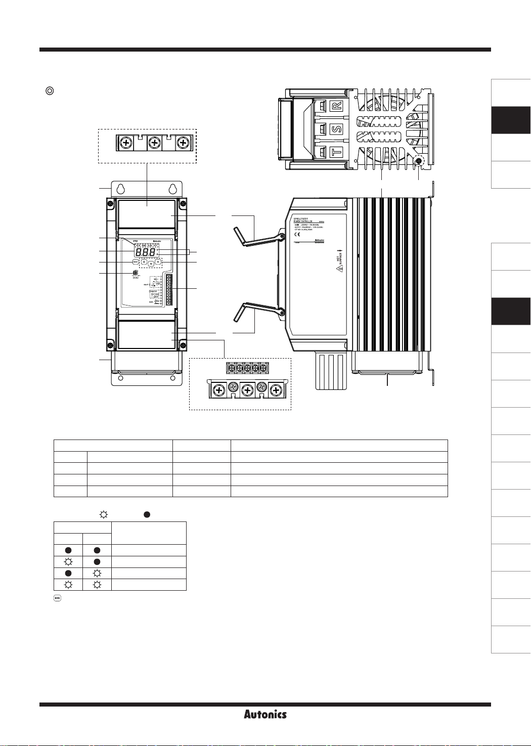
SPR3 Series
⑩
①
②
③
⑤
⑦
⑬
R S T
SENSORS
CONTROLLERS
MOTION DEVICES
SOFTWARE
⑭
⑮
⑨
④
⑥
⑧
⑨
⑪
(J)
Temperature
Controllers
(K)
SSRs
(L)
Power
Controllers
(M)
Counters
(N)
Timers
⑫
⑬
U V W
①
Bracket (except rated load current 100A/150A models)
②
Indicator
Indicator Color Function
RUN Operation indicator Green LED Turns on in the RUN mode.
MAN Manual control indicator Green LED Turns on when adjusting load output in the manual control mode.
ALM Alarm indicator Red LED Flashes in alarming status.
OUT Output indicator Red LED Turns on when load control outputs.
③
Display part: Displays settings of the front display [
④
Unit indicator ( : Light ON/ : Light OFF)
Indicator
V A
Display
Resistance, load
Voltage
Current
Power
⑤
key: Enters parameter group, returns to RUN mode, moves parameters, and saves the setting value.
⑥
Setting value adjustment key: Enters SV setting mode and move digits.
⑦
Output limit adjuster (OUT ADJ): Limits output from 0 to 100%.
⑧
11-pin connector terminal
⑨
Terminal cover
⑩
R, S, T load input terminal
⑪
Alarm output and power input terminals
⑫
U, V, W Load output terminals
⑬
Cooling fan: For models with the rated load current of 70A/100A/150A, a cooling fan is attached.
⑭
Heatsink: In case of rated load current 100A/150A models, there are mounting holes on the right/left.
⑮
Bolt for grounding (M4)
DIS
] parameter in RUN mode, and displays parameter and setting value in setting mode.
(O)
Digital
Panel Meters
(P)
Indicators
(Q)
Converters
(R)
Digital
Display Units
(S)
Sensor
Controllers
(T)
Switching
Mode Power
Supplies
(U)
Recorders
(V)
HMIs
(W)
Panel PC
(X)
Field Network
Devices
SPR1/SPR3 Series
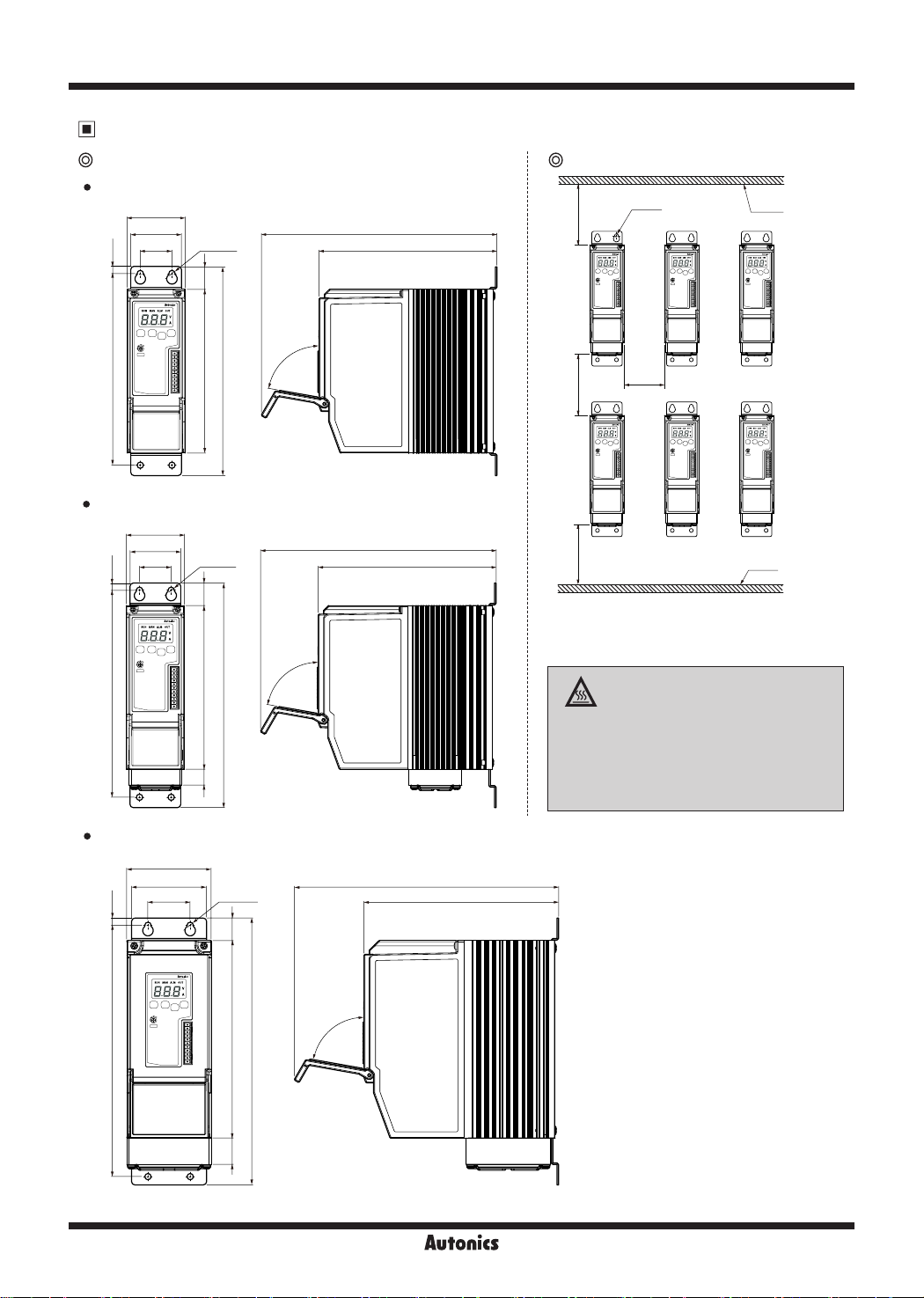
Dimensions
Rated load current 25A/35A/50A
55
48
30 168.5
6.8
181
Rated load current 70A
55
48
30
6.8
196
4-Ø6
21.3
155
4-Ø6
21.3
155
15
80°
197.6
80°
212.6
223
223
168.5
(unit: mm)
Spacing SPR1 Series
4-Ø6
100100100
50
※
When installing multiple power controllers,
please keep space at least 50mm in horizontal
and 100mm in vertical between power controllers
for heat radiation.
Panel
Panel
High Temperature Caution
While supplying power to the load or right
after turning o the power of the load, do
not touch the body and heatsink.
Failure to follow this instruction may result in
a burn due to the high temperature.
Rated load current 100A/150A
80
6.8
238
71
40
4-Ø6
21.3
80°
187
252.6
25
250.1
184.4
L-16 L-17
 Loading...