

Autonics SPC1 Series Catalog Page
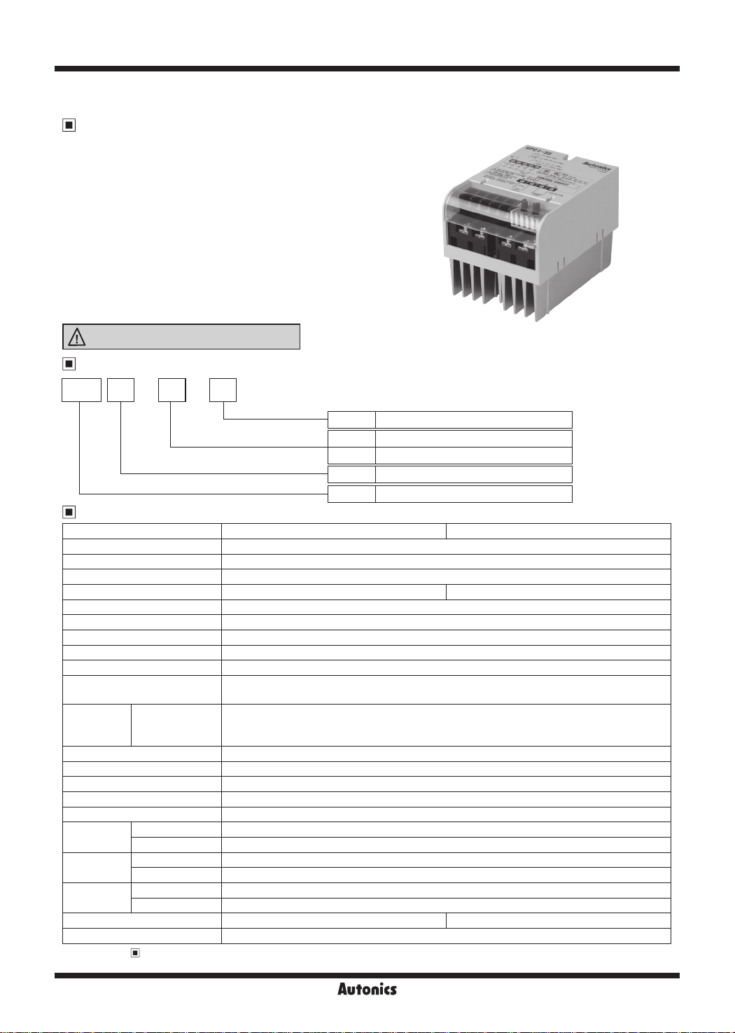
SPC1 Series
Single-Phase, Power Controller
Features
● Various and simple input specication
• DC4-20mA, 1-5VDC, External 24VDC
• External adjuster (1kΩ)
• External contact (ON/OFF)
● Various function
• OUT ADJ (output limit) function
•
SOFT START function (except for ON/OFF control method)
• OUT display function
• 50/60Hz automatic converting function
● Various control method by switch
• Phase control method
• Cycle control method (zero cross turn-on)
• ON/OFF control method (zero cross turn-on)
Please read “Safety Considerations”
in the instruction manual before using.
Ordering Information
SPC 35 E1 - -
Marking language
Rated load current
Control phase
Item
Specications
Model SPC1-35-E SPC1-50-E
Power supply 220VACᜠ 50/60
Allowable voltage range 90 to 110% of rated voltage
Operating frequency uctuation
Rated load current 35A (single-phase) 50A (single-phase)
Control power 220VAC
Control range Phase control: 0 to 98%, Cycle control: 0 to 100%
Applied load Resistance load (min. load: over 5% of rated current)
Cooling method Natural cooling
Control circuit Micom control type
Control input
Control
method
Starting type SOFT START (0 to 50 sec variable)
Indicator Output indicator (OUT): red LED
Insulation resistance Over 100MΩ (at 500VDC megger)
Dielectric strength 2000VAC 50/60Hz for 1 min
Noise immunity ±2kV the square wave noise (pulse width: 1㎲) by the noise simulator
V bration
Shock
Environment
Wire specication
Unit weight Approx. 1kg
※
Refer to '
1:
※
Environment resistance is rated at no freezing or condensation.
L-6
By selection
switch
Mechanical
Malfunction
Mechanical 300m/s² (approx. 30G) in each X, Y, Z direction for 3 times
Malfunction 100m/s² (approx. 10G) in each X, Y, Z direction for 3 times
Ambient temp. 0 to 50℃, storage: -25 to 65
Ambient humi. 35 to 85%RH, storage: 35 to 85%RH
Operation and Function'.
±1Hz
ᜠ
• 1-5VDCᜡ • DC4-20mA (250Ω) • ON/OFF (external relay contact or 24VDCᜡ)
• External adjuster (1kΩ) • Output limit input (front OUT
• Phase control
• Cycle control (zero cross turn-on) - Period 0.5 sec, 2.0 sec, 10 sec
• ON/OFF control (zero cross turn-on)
0.75mm amplitude at frequency of 10 to 55Hz (for 1 min) in each X, Y, Z direction for 1 hour
0.5mm amplitude at frequency of 10 to 55Hz (for 1 min) in each X, Y, Z direction for 10 min
AWG16 to 8 AWG8 to 6
E English
35 35A
50 50A
1 Single-phase
SPC Solid state power controller
Hz
※
1
℃
Autonics
ADJ. adjuster)
※
1
Single-Phase, Power Controller
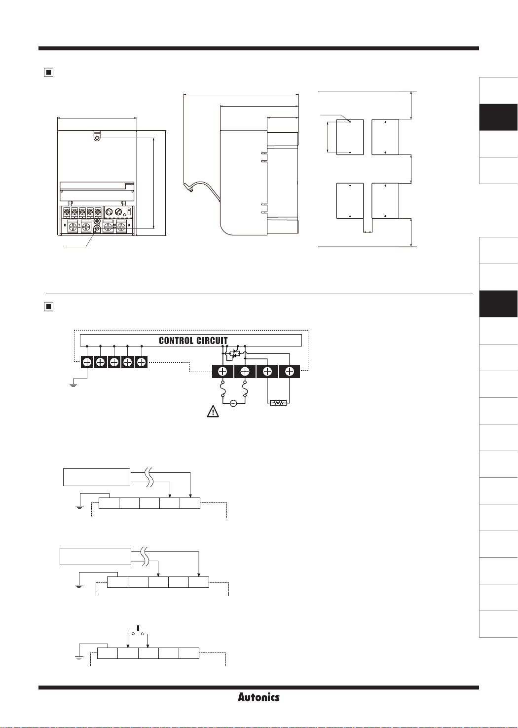
Dimensions
94.6
136.9
93.2
37.2
● Spacing
2-M4
10
108
124.8
2-Ø4.2
※
Connections
1. External connection
··········································coNTiiOLCiRCiiiT························
2 3 4 5
1
F.G.
____
+5V IN
2. Connection of control input terminals
1) DC4-20mA control input
It controls 0 to 100% when you apply DC4-20mA on
Sensor or other
controlling equipmen
1 2 3 4 5
F.G.
2) 1-5VDC control input
It controls 0 to 100% when you apply 1-5VDC on
Sensor or other
controlling equipment
l
3) ON/OFF external contact control input
It controls 100% if you connect external contact or switch to
GT7
- !
1 2 3 4 5
-----1
1
F.G.
7
1 2 3 4 5
l~l----'----l~
F.G.
IN 0V
+5V
+5V
_J_
Cl
+5V
------------
Rapid fuse
(external
attachment)
(+)
IN
IN
1-5VDC
(+)
IN
IN
External contact
or switch
IN
IN
GND
GND
R
:__________
SOURCE
220VAC
50/60
DC4-20mA
(-)
③, ⑤
(-)
l
I
1-----------l
GND
If--------------]
T
Hz
④, ⑤
terminals when power is applied.
W U
LOAD
(resistive load only)
terminals when power is applied.
※
This function must not be used in ON/OFF control method.
※
This function must not be used in ON/OFF control method.
terminal when it is ON, it controls 0% when it is OFF.
②, ③
※
It is available for all control methods.
OUT ADJ and SOFT START functions are not available
in ON/OFF control method.
·1
_
__
:
(unit: mm)
100
108
'
100
30
100
When installing multiple power controllers,
please keep space at least 30mm in
horizontal and 100mm in vertical between
power controllers for heat radiation.
SENSORS
CONTROLLERS
MOTION DEVICES
SOFTWARE
(J)
Temperature
Controllers
(K)
SSRs
(L)
Power
Controllers
(M)
Counters
(N)
Timers
(O)
Digital
Panel Meters
(P)
Indicators
(Q)
Converters
(R)
Digital
Display Units
(S)
Sensor
Controllers
(T)
Switching
Mode Power
Supplies
(U)
Recorders
(V)
HMIs
(W)
Panel PC
(X)
Field Network
Devices
Autonics
L-7
 Loading...