

SPA Series
Switching mode power supply with minimized noise and ripple
Features
● Built-in overcurrent protection, output short-circuit protection,
overheating and overvoltage protection circuits(SPA-075/100)
● Standard on safety IEC 60950, IEC 50178
● EMS(Electromagnetic susceptibility) EN61000-6-2
● EMI(Electromagnetic interference) EN61000-6-4
● Output voltage : 5VDC, 12VDC, 24VDC
● Output current : 30W, 50W, 75W, 100W
Please read “Caution for your safety” in operation
manual before using.
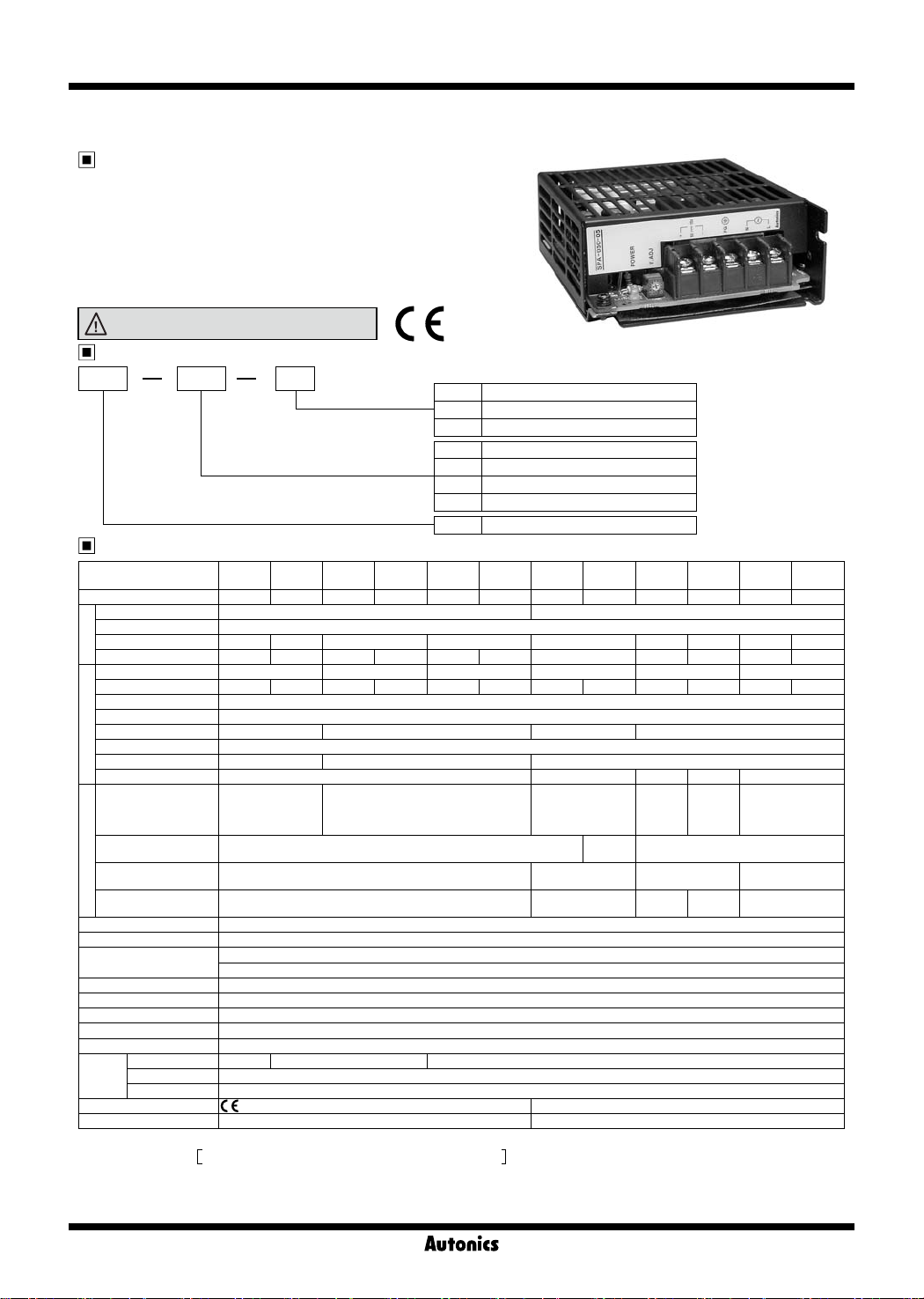
Ordering information
SPA 030 24
Output voltage
Output power
Item
Specifications
SPA-
SPA-
Model
Capacity 30W 50W 30W 50W 30W 50W 75W 100W 75W 100W 75W 100W
Power supply
Frequency 50/60Hz
Efciency
Input
Current consumption
Voltage 5VDC 12VDC 24VDC 5VDC 12VDC 24VDC
Current 6A 10A 2.5A 4.2A 1.5A 2.1A 15A 20A 6.3A 8.5A 3.2A 4.2A
Votage adjustment range
Input uctuation ratio
Load uctuation ratio
Output
Ripple
Starting time
Holding time
Inrush current
protection
Output overcurrent
protection
Output overvoltage
Protection
protection
Output short-circuit
protection
Output indicator Green LED
Insulation resistance Min. 100MΩ(between all input and output terminals with 500VDC)
Dielectric strength
Vibration 0.75mm amplitude at frequency of 10 to 55Hz(for 1 min.) in each of X, Y, Z directions for 2 hours
Shock 300m/s² (approx. 30G) in each of X, Y, Z directions for 3 times
EMS
EMI Conforms to EN61000-6-4
Protection IEC60950, IEC50178 standard
Environ
-ment
Approval
Unit weight Approx. 350g Approx. 400g
※
1: 100% load for rated input voltage(100VAC).
※
2: Rated input voltage •SPA-030/050 Series : 100-240VAC(85-264VAC)
•SPA-075/100 Series : 100-120/200-240(85-132/170-264VAC)
SPA-100-05 is under 100% of load for [100-120/200-240VAC(100-132/190-264VAC)].
※
3: Rated input voltage(100VAC). ※4: Vary voltage by output voltage adjuster, it is changed over voltage variation range(±5%).
※
5: The rated input volatge of SPA-100-05 is 100-120/200-240VAC(100-132/190-264VAC).
※
Environment resistance is rated at no freezing or condensation.
※
5
※
1
※
1
※
1
※
1
※
3
Ambien temperature
Storage temperature -25 to 65
Ambient humidity 25 to 85%RH, storage: 25 to 90%RH
030-05
100-240VAC(85-264VAC) 100-120/200-240VAC(85-132/170-264VAC) switching type
Min. 60% Min. 67% Min. 74% Min. 80% Min. 70% Min. 78% Min. 72% Min. 78% Min. 80%
※
1
Max. 1.2A Max. 1.6A Max. 1.0A Max. 1.4A Max. 0.8A Max. 1.1A Max. 3.0A Max. 2.0A Max. 3.0A Max. 2.0A Max. 2.5A
※
4
±5%
※
2
Max. ±0.5%
※
1
Max. ±2% Max. ±1% Max. ±2% Max. ±1%
Max. ±1%
Max. 200ms Max. 150ms Max. 250ms
Min. 10ms Min. 5ms
Max. 30A(100VAC)
Max. 40A(200VAC)
Min. 110%
-
Max. 5ms Max. 10ms Max. 5ms
3.0kVAC 50/60Hz for 1 min. (between all input and output terminals)
1.5kVAC 50/60Hz for 1 min. (between all input terminals F.G)
Conforms to EN61000-6-2
-10 to 50℃-10 to 40
℃
(except 5VDC)
P-8
050-05
SPA030-12
Max. 20A(100VAC)
℃
(except 5VDC)
SPA-
SPA-
050-12
030-24
-10 to 50
05 5VDC
12 12VDC
24 24VDC
030 30W
050 50W
075 75W
100 100W
SPA Switching Mode Power Supply
SPA-
SPA-
050-24
℃
under 100% of load.
SPA-
075-05
100-05
Max. 45A(100VAC)
/Max. 50A(240VAC)
Min.
105%
6.5V ±10% 16V ±10% 30V ±10%
-
SPA075-12
Min. 10ms
Max. 35A
(100VAC)
/Max. 40A
(240VAC)
Min. 110%
SPA-
SPA-
100-12
075-24
Min. 5ms Min. 10ms
Max. 45A
(100VAC)
Max. 35A(100VAC)/
/Max. 50A
Max. 40A(240VAC)
(240VAC)
Min. 10ms
Max. 5ms
SPA100-24
General Purpose Type Switching Mode Power Supply
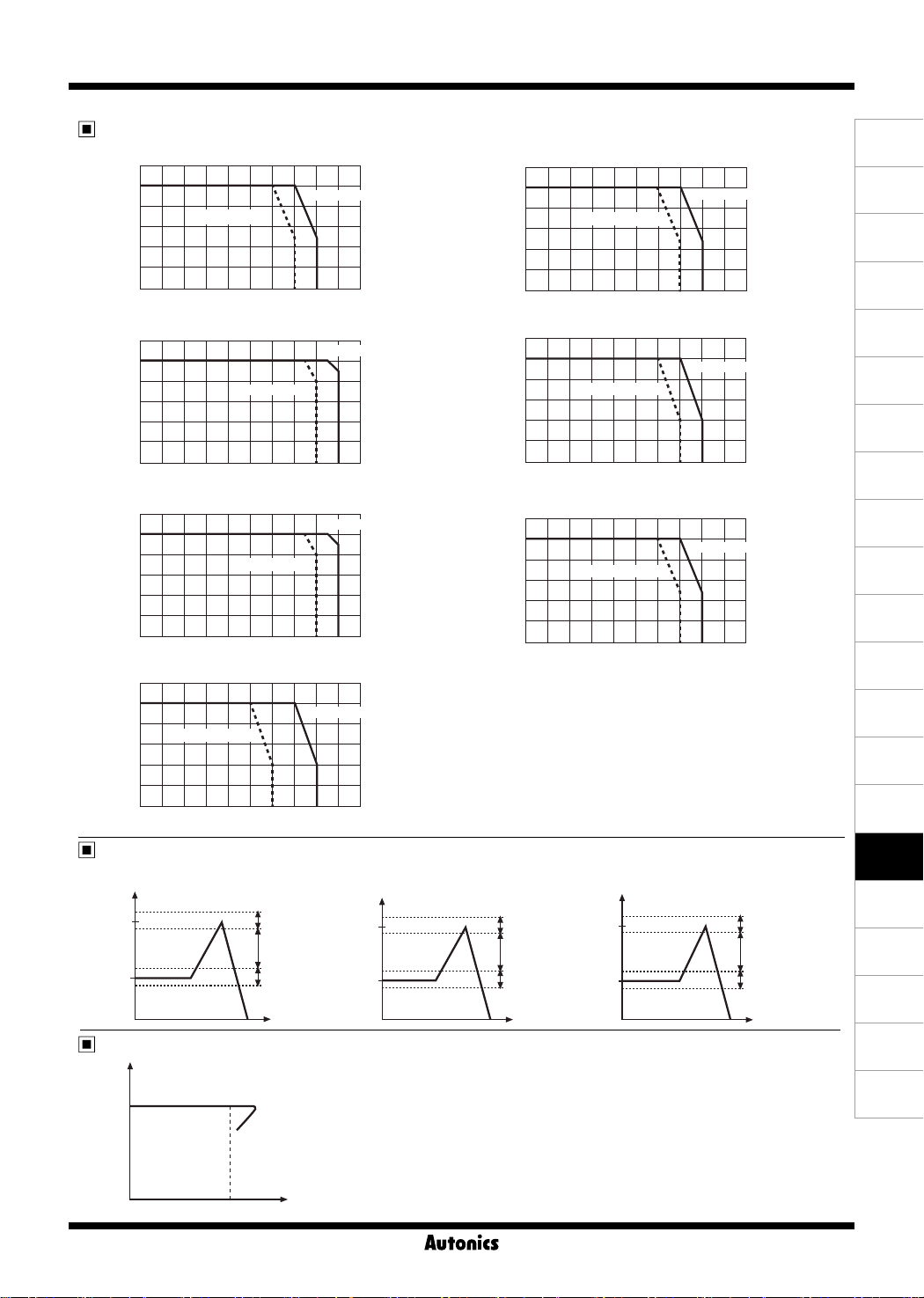
Output feature data for ambient temperature
● SPA-030-05
120
Load
ratio
100
(%)
80
60
Natural cooling
40
20
0
-10 0 10 20 30 40 50 60 70 80
● SPA-030-12 ● SPA-050-12
120
Load
ratio
100
(%)
80
60
Ambient temperature (℃)
Natural cooling
40
20
0
-10 0 10 20 30 40 50 60 70 80
● SPA-030-24 ● SPA-050-24
120
Load
ratio
100
(%)
80
60
Ambient temperature (℃)
Natural cooling
40
20
0
-10 0 10 20 30 40 50 60 70 80
● SPA-050-05
120
Load
ratio
100
(%)
80
60
Natural cooling
Ambient temperature (℃)
40
20
0
-10 0 10 20 30 40 50 60 70 80
Ambient temperature (℃)
Forced cooling
90
Forced cooling
90
Forced cooling
90
Forced cooling
90
● SPA-075-05 ● SPA-100-05 ● SPA-100-12
Load
120
ratio
100
(%)
80
60
Natural cooling
Forced cooling
40
20
0
-10 0 10 20 30 40 50 60 70 80
Ambient temperature (℃)
90
● SPA-075-12
Load
120
ratio
(%)
100
80
Natural cooling
Forced cooling
60
40
20
0
-10 0 10 20 30 40 50 60 70 80
Ambient temperature (℃)
90
● SPA-075-24 ●SPA-100-24
Load
120
ratio
100
(%)
80
60
Natural cooling
40
20
0
-10 0 10 20 30 40 50 60 70 80
Ambient temperature (℃)
Forced cooling
90
Feature data for output overvoltage protection
● SPA-075-05 / SPA-100-05 ● SPA-075-12 / SPA-100-12 ● SPA-075-24 / SPA-100-24
Output
voltage
6.5V
Operation range of
overvoltage protection
function[6.5V ±10%]
Output voltage range
can not be covered
within standard
5V
0V
Output voltage uctuation range
[5V ±5%]
Output
voltage
16V
12V
Operation range of
overvoltage protection
function[16V ±10%]
Output voltage range
can not be covered
within standard
Output voltage
uctuation range
[12V ±5%]
0V
Output
voltage
30V
24V
Operation range of
overvoltage protection
function[30V ±10%]
Output voltage range
can not be covered
within standard
Output voltage
uctuation range
[12V ±5%]
0V
Feature data of overcurrent protection
Output
voltage
(V)
Rated
Output current (%)
● It is when the rated input voltage is 100VAC, 100%.
● It is able to protect overcurrent by load with built-in
overcurrent protection circuit.
When the over rated current is owed, the circuit is
operated (output voltage is fallen) and it is cancelled
when the load current is under the rated current. (it is
returned to the rated output voltage)
(A)
Photo
electric
sensor
(B)
Fiber
optic
sensor
(C)
Door/Area
sensor
(D)
Proximity
sensor
(E)
Pressure
sensor
(F)
Rotary
encoder
(G)
Connector/
Socket
(H)
Temp.
controller
(I)
SSR/
Power
controller
(J)
Counter
(K)
Timer
(L)
Panel
meter
(M)
Tacho/
Speed/ Pulse
meter
(N)
Display
unit
(O)
Sensor
controller
(P)
Switching
mode power
supply
(Q)
Stepper
motor&
Driver&Controller
(R)
Graphic/
Logic
panel
(S)
Field
network
device
(T)
Software
(U)
Other
P-9

SPA Series
Block diagram
Input power
85-264VAC
50/60Hz
(L)
(N)
F·G
DC OUT
0V
+V
Noise
lter
Inrush current
protection
circuit
Overcurrent
protection
circuit
Rectier
circuit
Control
circuit
Dimensions
● SPA-030/050 Series ● SPA-075/100 Series
55
LED LED
VR
5-M3.5
3.5
6
4
2-M3
(Bottom side)
114
33
4
VR
87
45.5
97
5-M3.5
3.5
6
4
2-M3
(Bottom side)
Rectier
circuit
100
154
Voltage
detection
30.4
(unit: mm)
4
87
97
38.5
9.5
7.5
3.5
28
17.5
Front part identification
1
2
3
4
5
6
7
P-10
3.5
40
28
3.5
83
114
120
25
29
22.5
138
154
160
1. Output display LED(green)
2. Output voltage adjuster
※
V.ADJ(voltage variable range: ±5% of the rated output voltage)
3. Output power [+] terminal
4. Output power [-] terminal
5. [F.G] terminal
6. Input power [N] terminal
7. Input power [L] terminal
20
10
3.5
42
29

General Purpose Type Switching Mode Power Supply
Proper Usage
For switch input voltage type, input voltage is 220V as
factory default. To swich input voltage for 110V, remove
the cover then select proper jumper switch as below
figures.
110V
220V
Technical information of operation
This product is not available to operate of output voltage
as parallel and series.
The output current should be used within the rated range.
When it is operated in overcurrent status, the life span of
product can be shortened.
The output voltage should be used within the rated range.
When the output overvoltage limit function is operated,
the product operated normally with cancellation of input
power for few minutes.
The overvoltage limit function is operated when it is
exceeded the rated output voltage range with an output
voltage adjuster.
This product has overheating protection function. It is
operated normally when releasing the load connection for
few minutes.
The power factor is within 0.5 to 0.7 using condenser
rectified method. Please use the below formula and check
the input power capacity when using a cabinet panel or
transformer.
Active Power [W]
Apparent power[VA] =
This product does not have harmonics suppression and
power factor correction circuit.
Please mount the device for it.
This product has a noise filter, it can be changed with the
mounting place and connection.
Please change as a same rated fuse when the inner fuse
is broken.
Power factor×Efficiency
Caution for mounting
Please mount the device on metal panel for the reliability.
Please mount the device in a ventilative place for high
radiation of heat.
Please use the power line as below specification.
Input power line
specication
Model
AWG19 to 21 AWG16 to 18
SPA-030-05
SPA-030-12
SPA-050-12
SPA-075-12
SPA-030-24
SPA-050-24
SPA-050-05
SPA-075-05
SPA-100-05
SPA-100-12
SPA-075-24
SPA-100-24
(A)
Photo
electric
sensor
(B)
Fiber
optic
sensor
(C)
Door/Area
sensor
(D)
Proximity
sensor
(E)
Pressure
sensor
(F)
Rotary
encoder
(G)
Connector/
Socket
(H)
Temp.
controller
(I)
SSR/
Power
controller
(J)
Counter
(K)
Timer
(L)
Panel
meter
(M)
Tacho/
Speed/ Pulse
meter
(N)
Display
unit
(O)
Sensor
controller
(P)
Switching
mode power
supply
(Q)
Stepper
motor&
Driver&Controller
(R)
Graphic/
Logic
panel
(S)
Field
network
device
P-11
(T)
Software
(U)
Other
 Loading...