

DRW171405 A A
Autonics
SHAFT TYPE 5 PHASE
STEPPER MOTOR
INSTRUCTION MANUAL
24 42 60 85
Thank you for choosing our Autonics product.
Please read the following safety considerations before use.
Safety Considerations
~
Please observe all safety considerations for safe and proper product operation to avoid
※
hazards.
symbol represents caution due to special circumstances in which hazards may occur.
※
Failure to follow these instructions may result in serious injury or death.
Warning
Caution
Failure to follow these instructions may result in personal injury or product damage.
Warning
1. Fail-safe device must be installed when using the unit with machinery that may
cause serious injury or substantial economic loss. (e.g. nuclear power control,
medical equipment, ships, vehicles, railways, aircraft, combustion apparatus, safety
equipment, crime/disaster prevention devices, etc.)
Failure to follow this instruction may result in re, personal injury, or economic loss.
2. Fix the unit on the metal plate.
Failure to follow this instruction may result in personal injury, or product and ambient
equipment damage.
3. Do not connect, repair, or inspect the unit while connected to a power source.
Failure to follow this instruction may result in re.
4. Install the unit after considering counter plan against power failure.
Failure to follow this instruction may result in personal injury, or economic loss.
5. Check 'Connections' before wiring.
Failure to follow this instruction may result in re.
6. Do not disassemble or modify the unit.
Failure to follow this instruction may result in electric shock or re.
7. Install the motor in the housing or ground it.
Failure to follow this instruction may result in electronic shock, re, or personal injury.
8. Make sure to install covers on motor rotating components.
Failure to follow this instruction may result in personal injury.
9. Do not touch the unit during or after operation for a while.
Failure to follow this instruction may result in burn due to high temperature of the surface.
10. Turn OFF the power directly when error occurs.
Failure to follow this instruction may result in electric shock, re, or personal injury.
Caution
1. Use the unit within the rated specications.
Failure to follow this instruction may result in re or product damage.
2. Use dry cloth to clean the unit, and do not use water or organic solvent.
Failure to follow this instruction may result in re.
3. Do not use the unit in the place where ammable/explosive/corrosive gas, humidity,
direct sunlight, radiant heat, vibration, impact, or salinity may be present.
Failure to follow this instruction may result in re or explosion.
4. The motor may overheat depending on the environment.
Install the unit at the well-ventilated environment and forced cooling with a cooling fan.
Failure to follow this instruction may result in product damage and degrada ion.
Ordering Information
S 4A 5 3 W1K
Motor frame size
(width×length)
Motor phase
.______
Rated current
Max. Holding torque
Standard wiring is optional.(Except
※1:
The above specications are subject to change and some models may be discontinued without notice.
※
Be sure to follow cautions written in the instruction manual and the technical descriptions
※
(catalog, homepage).
S
Wire connection
Shaft type
Motor length
24
□
2
(24×24mm)
42
□
4
(42×42mm)
60
□
6
(60×60mm)
85
□
9
(85×85mm)
_
24 motor model, A4K-G564(W), A8K-G566(W).)
□
_______J-------r====r=
□
No mark
Pentagon
1
※
S
Standard
No mark
Single shaft
W
Dual shaft
3
30.5mm
4
46.5mm
3
33mm
4
39mm
5
47mm
4
48.5mm
6
59.5mm
9
89mm
6
68mm
9
98mm
13
128mm
5
5 phase
S
0.75 A/Phase
_=
M
1.4 A/Phase
G
2 8 A/Phase
kgf.cm
Square
(Refer to motor specications)
A
utonics motor
________j=====::!
Specications
□24
I
Model 02K-S523(W) 04K-S525(W)
Max. Holding
1
※
torque
Rotor moment of
inertia
Rated current 0.75 A/Phase
Standard step angle 0.72 / 0 36 (Full/Half step)
2
※
Weight
□42
Model A1K-S543(W)-
Max. Holding
1
※
torque
Rotor moment of
inertia
Rated current 0.75 A/Phase
Standard step angle 0.72 /0.36 (Full/Half step)
2
※
Weight
□60
Model
Max. Holding
1
※
torque
Rotor moment
of inertia
Rated current
Standard step
angle
2
※
Weight
□85
Model
Max. Holding
1
※
torque
Rotor moment of
inertia
Rated current 1.4 A/Phase 2 8 A/Phase 1.4 A/Phase 2.8 A/Phase 1.4 A/Phase 2 8 A/Phase
Standard step angle 0.72 / 0 36 (Full/Half step)
2
※
Weight
1: Max. Holding torque is a retaining torque when 5 phase excitation stopped after the rated current
※
is flowed in motor.
2: The weight includes packaging. The weight in parentheses is for unit only.
※
Common specication
I
Insulation class B type (130℃)
Insulation resistance Over 100㏁ (at 500VDC megger) between Motor coil-case
Dielectric strength 1 kVAC(at 0.75 A/Phase is 0.5 kVAC) 50/60Hz for 1 minute between Motor coil-case
Temperature rise 5-Phase excitation for rated current, below 80℃ while stopped
Ambient
temperature
Ambient humidity 35 to 85%RH, Storage: 35 to 85%RH
Environment
I
Positional accuracy
Shaft vibration
Radial Movement
Axial Movement
Concentricity for shaft of
setup in-low
Perpendicularity of setup plate shaft
Protection structure IP30 ( EC34-5 standards)
1: Specications are for full-step angle, with no-load. (Values may vary by load size.)
※
2: Amount of radial shaft displacement when adding a radial load(5N) to the tip of the motor shaft.
※
3: Amount of axial shaft displacement when adding an axial load(10N) to the shaft.
※
4: T.I.R (Total Indicator Reading): The difference between the maximum and minimum readings of a dial
※
gauge during one complete revolution of the monitored reference.
Environment resistance is rated at no freezing or condensation.
※
0.18 kgf cm
(0.018 N.m)
2
4.2 g.cm
(4.2x10⁻⁷ kg m2)
Approx. 0.10kg (approx. 0.08kg) Approx. 0.16kg (approx. 0.12kg)
A4KG564(W)
0.075
A2K-S544(W)-
1 8 kgf.cm
(0.18 N m)
54 g.cm
(54x10-7 kg m2)
Approx. 0.39kg
(approx. 0.3kg)
I
A8KS566(W)-
8.3 kgf cm
(0.81 N.m)
280 g.cm
(280x10-7 kg.m2)
0.75 A/Phase
A41K-
M599(W)-
□
41 kgf cm
(4.0 N m)
2,700 g cm
(2,700x10-7 kg.m2)
Approx. 3.25kg
(approx. 2.8kg)
A
A
□
1.3 kgf cm
(0.13 N.m)
2
35 g cm
(35x10-7 kg.m2)
Approx. 0 34kg
(approx. 0 25kg)
A4K-
A4K-
S564(W)-
M564(W)-
□
4 2 kgf.cm
(0.41 N m)
175 g.cm
(175x10-7 kg m2)
0.75 A/Phase
0.72 /0 36 (Full/Half step)
Approx. 0.85kg (approx. 0 6kg) Approx. 1.05kg (approx. 0 8kg)
A21K-
M596(W)-
21 kgf.cm
(2.1 N.m)
1,400 g.cm
(1,400x10-7 kg m2)
Approx. 2.15kg
(approx. 1.7kg)
1
※
4
※
2
※
3
※
□
2
1.4 A/Phase 2.8 A/Phase
A21K-
G596(W)-
□
2
-10 to 50℃, Storage: -25 to 85
±3' (±0 05 )
0.05mm T.I.R.
Max. 0 025mm (Load 5N)
Max. 0 075mm (Load 10N)
0.075mm T.I.R.
0.075mm T.I.R.
Ø
┻
0.28 kgf cm
(0.027 N.m)
2
8.2 g cm
(8.2x10⁻⁷ kg m2)
I
A8KG566(W)
□
□
A
A3K-S545(W)-
2.4 kgf cm
(0 24 N.m)
2
68 g cm
(68x10-7 kg.m2)
Approx. 0.49kg
(approx. 0.4kg)
I
A16KM569(W)-
16.6 kgf cm
(1.63 N.m)
560 g.cm
(560x10-7 kg.m2)
Approx. 1 55kg
(approx. 1.3kg)
A63K-
M5913(W)-
63 kgf.cm
(6 2 N.m)
4,000 g.cm
(4,000x10-7 kg m2)
Approx. 4 25kg
(approx. 3 8kg)
□
2
A8KM566(W)-
□
2
1.4 A/Phase 2.8 A/Phase 1.4 A/Phase 2.8 A/Phase
A41K-
G599(W)-
□
2
℃
Ø0 075
◎
0 05
↗
□
A63K-
G5913(W)-
□
2
□
2
A16KG569(W)-
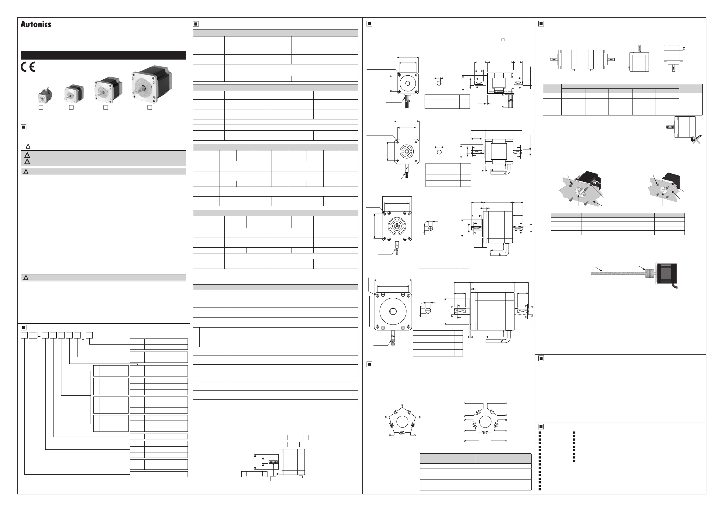
Dimensions
The dimensions are for dual shaft models.
※
Single shaft models do not include shafts indicated in the dotted lines.
For flexible coupling (ERB Series) information, refer to the catalogue. (Except for
※
24
□
◎
4-M2.6
Depth
2.5
±0.25
AWG 26
UL 3265
42
□
◎
4-M3
Depth 4.5
±0.2
60
□
±0.3
50
85
□
Tap
AWG 24
UL 3266
AWG 22
UL 3266
31
AWG 26
UL 3266
70
□
◎
4-Ø4 5
Tap
□
◎
4-Ø6.5
±0.3
70
24
□
±0.25
19
0,o
19
42
□
±0.2
31
60
□
±0.3
50
85
□
±0.3
Sectioned A-A'
Model L
02K-S523(W) 30.5
04K-S525(W) 46.5
Sectioned A-A'
Model L
A1K-543(W)-
A2K-544(W)-
A3K-545(W)-
±0.15
7.5
90
±0.15
7.5
Sectioned A-A'
Model L
564(W)-
A4K-
□
A8K-
566(W)-
□
A16K-
□
±0.15
13
90
±0.15
13
Sectioned A-A'
Model L
596(W)-
A21K-
□
A41K-
599(W)-
□
A63K-
5913(W)-
□
±0.2
4 5
±0.15
4 5
569(W)-
□
□
±0.5
±0.5
A'
2
A
7
Ø5, 0.6m
Ø7, 0 6m
L
L
Ø5, 0 6m
±1
L
±1
L
±1
15
10
~
0
0
-0.025
-0.012
Ø5
Ø18
1 5
±0.5
20
±0.25
15
0
□
□
□
0
□
□
□
25
0
-0.0 6
0
-0.018
Ø14
Ø60
68
98
128
□
-0.021
Ø22
-0.039
Ø36
48 5
59 5
89
37
±0.25
A
0
-0.012
Ø5
A'
33
39
47
±1
24
±0.25
20
A
0
-0.015
Ø8
A'
1 5
±1
10
A
A'
2
Connection Diagram
Refer to the below for correlations of motor's each phase(coil) and the color of lead wire.
Note that Pentagon connection type is a standard model. Standard connection type is an option
model.
●
Pentagon connection type (Standard)
Blue
E phase
Black
D phase B phase
WI
Green
In case of connecting standard
connection type models to
motor drivers, make sure that
motor's lead wire connection
must be made as specified in
the table.
C phase
A phase
Orange
Yellow
I
Red
or
Lead wire color for Standard
connection type
Gray + Red Blue
Yellow + Black Red
Orange + White Orange
Brown + Green Green
Blue + Purple Black
●
Standard connection type (Option)
Green
E phase A phase
Orange Black
Joe
Blue Purple
D phase B phase
Red
3 C
:______re
White
C
phase
Lead wire color for Pentagon
connection type
85)
□
±1
Min. 200
(Unit: mm)
20
Gray
Brown
Yellow
±1
10
d
A
A'
±1
15
A
A'
±1
21
±0.25
A
A'
±1
32
±0.25
25
A
A'
Motor Installation
1. Motor installation direction
The motor can be installed in any direction horizontally, or vertically. Please take careful
consideration of shaft overhung load and thrust load under all conditions. Please refer to the table
below for permissible overhung load and thrust load of the shaft.
0
-0.012
Ø5
0
-0.012
Ø5
0
-0.015
Ø8
0
-0.018
Ø14
I
-[DUg~
Motor size
24 2(20) 2.5(25) 3.4(33) - -
□
42 2(20) 2.5(25) 3.4(33) 5 2(51) -
□
60 6.3(62) 7.5(74) 9 5(93) 13(127) 19(186)
□
85 26(255) 29(284) 34(333) 39(382) 48(470)
□
When installing the motor, make sure that excessive force is not applied
to the motor cable. Also, the motor cable must not be pulled or inserted
too tightly. If the motor is operated with excessive force applied on the
cable, it may result in failed contact or disconnection. Please take safety
measures when excessive force or continuous operation is required.
2. Motor installation method
When installing the motor, carefully consider heat radiation and vibration resistance. Mount the unit
tightly on the surface of a metal with high thermal conductivity. (steel, aluminum, etc.)
Use hexagon bolts, spring washers and flat washers when installing the motor.
Please refer to the table below for mounting plate size and bolt types.
●
Through hole type
Hexagon socket bolt
Flange In Low
(Counter bore or Through hole)
I
Motor size Mounting plate size (depth) Bolt type
24 Min. 3mm M2.6
□
42 Min. 4mm M3
□
60 Min. 5mm M4
□
85 Min. 8mm M6
□
3. Load connection
Use a flexible coupling when attaching a load (ball-screw, TM-screw, etc.) directly on the shaft of
the motor. If the center does not match the load, vibration, degradation of the bearing, motor shaft
damage, or other problems may occur. When attaching the load, do not modify or disassemble the
motor or the shaft. When attaching the load of pulleys or belt please consider the thrust load, radial
load, and shock.
※
For flexible coupling(ERB Series) information, refer to the catalogue.
4. Installation conditions
Please install the motor under the following conditions. Usage outside these conditions may result
in product damage.
Indoor environment (this product is inteded for use with machinery.)
①
Ambient temperature : -10℃ to 50℃ (non-freezing status)
②
Ambient humidity : 35% to 85%RH (non-condensation)
③
Environments without explosive, flammable, or corrosive gas
④
Environments without explosure to direct sunlight
⑤
Environments with minimal dust
⑥
Environments without direct contact with water or oil
⑦
Environments suitable for heat dissipation
⑧
Environments without concentrated vibration or excessive shock
⑨
Environments with low salinity
⑩
Environments with minimal electromagnetic noise from other machinery
⑪
Environments without radioactive substances or magnetic fields
⑫
Must be installed in a non-vacuum state.
Cautions during Use
1. Follow instructions in 'Cautions during Use'. Otherwise, It may cause unexpected accidents.
2. Using motors at low temperature may cause reducing ball bearing's grease consistency
and friction torque is increased.
Start the motor in a steady manner since motor's torque is not to be influenced.
3. For using motor, it is recommended to maintenance and inspection regularly.
Unwinding bolts and connection parts for the unit installation and load connection
①
Strange sound from ball bearing of the unit
②
Damage and stress of lead cable of the unit
③
Connection error with driver
④
Inconsistency between the axis of motor output and the center, concentric (eccentric, declination)
⑤
of the load, etc.
4. This unit may be used in the following environments.
Indoors (in the environment condition rated in 'Specifications')
①
Altitude max. 2,000m
②
Pollution degree 2
③
Installation category II
④
Major Products
~
Photoelectric Sensors Temperature Controllers
■
Fiber Optic Sensors Temperature/Humidity Transducers
■
Door Sensors SSRs/Power Controllers
■
Door Side Sensors Counters
■
Area Sensors Timers
■
Proximity Sensors Panel Meters
■
Pressure Sensors Tachometer/Pulse (Rate) Meters
Rotary Encoders Display Units
Connectors/Sockets Sensor Controllers
Switching Mode Power Supplies
Control Switches/Lamps/Buzzers
I/O Terminal Blocks & Cables
Stepper Motors/Drivers/Motion Controllers
Graphic/Logic Panels
Field Network Devices
Laser Marking System (Fiber, CO₂, Nd: YAG)
Laser Welding/Cutting System
I
Horizontal Vertical
Permissible overhung load [kgf(N)] by distance from shaft tip (mm)
0 5 10 15 20
Spring washer
Flat Washer
Hexagon nut
Through hole
Mounting plate
Ball screw or TM screw Flexible coupling
■
■
■
■
■
■
■
■
■
facing up
●
Tap hole type
Hexagon socket bolt
Flange In Low
(Counter bore or Through hole)
facing down
Stepper
Motor
Vertical
Unit: kgf(N)
Permissible
thrust load
Under the
load of motor
Tap hole
Mounting plate
-
-
-
DRW171405AA
 Loading...