

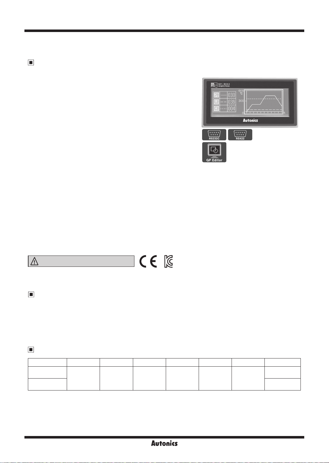
GP-S044 Series
Basic Type 4.4 inch Mono LCD Graphic Panel
Features
● Displays max. 400 characters
● Enables to save max. 500 pages of user screen
● Easy software upgrade available on website
(1) GP rmware le
(2) GP Editor (drawing program)
(3) Additional protocol
● Dierent devices monitoring function
: Allows to monitor and control the variables of
additionally connected controllers (such as PLC) with
external communication port
● Supports multilingual
: Supports Korean, Japanese, English, Chinese,
Russian, Vietnamese and Portuguese.
Additional languages will be available by rmware.
● Supports multi-font
: It provides various bitmap and user-selected fonts.
● Various multi-communication port
: Both RS232C 2 port and RS232C/RS422 compound port are provided.
● Device monitoring function
: It enables to monitor GP devices and connected controller devices by GP without graphic design data.
●Printer and barcode reader connection
: It enables to print alarm history connecting a printer and read barcode connecting a barcode reader.
● Compact design
● Various display function
: It displays data by various tags.
Please read “Safety Considerations”
in the instruction manual before using.
※
GP-S044 Series is a replacement of GP-2480 Series, discontinued product.
Manual
● GP Editor user manual
It describes how to write screen data, and is about related usage of GP-S044 HMI function.
● GP/LP user manual for communication
It describes connection for external devices such as PLC.
● GP-S044/S057 user manual
It describes general information on the installation and usage of GP-S044 and system contents.
Ordering Information
Model Item Series Monitor size Display unit Color Power supply Interface
GP-S044-S1D0
GP-S044-S1D1
Graphic panel S series 4.4 inch STN LCD
MONO
(blue, white)
24VDCᜡ
Each port of
RS232C, RS422
Two ports of
RS232C
V-38
Autonics
Basic Type 4.4 inch Mono Graphic Panel
Specifications
Model GP-S044-S1D0 GP-S044-S1D1
Power supply 24VDCᜡ
Allowable voltage range 90 to 110% of power supply
Power consump ion Max. 3.6W
LCD type 4.4 inch STN Blue Negative
Resolution 240×80 dots
Display area 112.8×37.6mm
Color MONO (blue, white)
LCD view angle Top/Bottom/Left/Right within 30° in each direction
Backlight White LED
Brightness Adjustable by software
Display performance
Language
※
1
English, Korean, Japanese, Chinese, Russian, Vietnamese, Portuguese
• High resolution display up to 400 letters (6×8 font)
Text
• 6×8, 8×8 ASCII characters, high deni ion numbers
• 8×16 ASCII characters, 16×16 character by each country
(1-8 times bigger for width, 0.5-5 times bigger for height)
Graphic drawing memory 512KB
performance
Number of user screen 500 pages
Graphic drawing
Touch switch Width 15×Height 4 = 60
Serial interface Each port of RS232C, RS422 (asynchronous method) Two ports of RS232C (asynchronous method)
Real-time controller RTC embedded
Battery life cycle Approx. 3 years at 25℃
Insulation resistance Over 100MΩ (at 500VDC megger)
Ground 3rd grounding (max. 100Ω)
Noise immunity ± 0.5kV the square wave noise (pulse width: 1㎲) by the noise simulator
Dielectric strength 500VAC (50/60Hz) for 1 min
Vibra ion
Shock
Environ
ment
Mechanical 0.75mm amplitude at frequency of 10 to 55Hz (for 1 min) in each X, Y
Malfunction 0.5mm amplitude at frequency of 10 to 55Hz (for 1 min) in each X, Y, Z direc
Mechanical 300m/s² (approx. 30G) in each X,
Y, Z direction for 3 imes
Malfunction 100m/s² (approx. 10G) in each X, Y, Z direction for 3 imes
Ambient temperature 0℃ to 50℃, storage: -20℃ to 60℃
Ambient humidity 35 to 85% RH, storage: 35 to 85% RH
Protec ion structure IP65 (front panel, IEC standard)
Accessory Fixing bracket: 4, waterproof rubber ring, battery (included)
Approval
※
2
Weight
※
1: Supported language can be added. ※2: The weight includes packaging. The weight in parenthesis is for unit only.
※
Environment resistance is rated at no freezing or condensation.
Function
~
;::=_
______
CE~
Approx. 413g (approx. 284g)
r--
______________________
Figure display Line, rectangle, circle, text, bitmap
Numeral display Displays the designated device as numerical value. (decimal, hexadecimal, octal, binary, real number)
ASCII display Displays the designated device value as ASCII character.
Time display Displays current time or date.
Alarm history Registers alarm history.
Alarm list Displays generated (not recovered) alarm.
Comment display Displays the designated comment as device status or value.
Lamp Displays lamp as device status.
Part display Displays the designated parts as device status and value.
Line graph Displays several device values with a graph of broken line.
Tags
Trend graph Displays change of device value for time with a graph of broken line.
Bar graph Displays a device value with a bar graph.
Statistic graph Displays a ratio of several device values with pie graph.
Panel meter Displays a device value as panel meter.
Touch key Screen is switched, word/bit device values are set when it touched.
Numeral input Congures user input value in device.
ASCII input Congures user input ASCII code value in device.
System information function Monitors/Controls GP operation from PLC.
Recipe function Reads/Writes several PLC device collectively.
Security function Only acceptable user can observe/operate important data.
Barcode read func ion Connects barcode reader, read barcode.
Floating alarm function Warning message is oated when alarm is generated.
Time operation Specic bit device is ON/OFF for designated day and time.
Overlap window Available to form dynamically overlapping another base screen on the base one.
Observe status function Changes PLC device status/value of PLC when trigger is generated.
I
I
, Z direction for 1 hour
ion for 10 min
SENSORS
CONTROLLERS
MOTION DEVICES
SOFTWARE
(J)
Temperature
Controllers
(K)
SSRs
(L)
Power
Controllers
(M)
Counters
(N)
Timers
(O)
Digital
Panel Meters
(P)
Indicators
(Q)
Converters
,_
__
(R)
Digital
Display Units
(S)
Sensor
Controllers
(T)
Switching
Mode Power
Supplies
(U)
Recorders
(V)
HMIs
(W)
Panel PC
(X)
Field Network
Devices
Autonics
V-39

GP-S044 Series
Dimensions
135
00000000000 00000000000
145
Unit Description
(unit: mm)
● Panel cut-out
Min. 170
+ 0.5
- 0
66
+0.5
136
-0
4 34
Min. 100
※
Panel thickness: max. 4mm
● Fixing bracket
75
65
83
LCD screen
9
M4 BOLT
21.7
12
Fixing bracket
※
Communication port
1:
Communication
Model
GP-S044-S1D0 RS422 RS232C
GP-S044-S1D1 RS232C-A RS232C-B
※
For more information, refer to '
Interface' of GP/LP Common Features.
Power
terminal
block
Communication
port A
※
Communication
1
port B
Battery case
※
1
Installation
1. Set a waterproof rubber ring after placing the joining part of the ring under the GP-S044.
2. Adhere closely between each edge of the GP-S044 and the rings.
3. Set GP-S044 in panel.
4. Set the fixing bracket to 4 bracket slots and fix them with the screw of the bracket.
=
00000000000 00000000000
CJ
00
OOOOOOOOHOO
Mounting slot
for bracket
00
=
CJ
Upper
side
Waterproof
rubber ring
Lower
side
● Fixing bracket
Port A Port B
port
Serial
M4 Screw driver
approx. 0.3N.m
Cable (sold separately)
Serial connection cables which connect GP/LP with PLC or other external devices are sold separately.
Refer to "GP/LP Communication Cables".
V-40
Autonics

Basic Type 4.4 inch Mono Graphic Panel
Serial Interface
● All devices are connectable with GP-S044 including PC, PLC, serial printer, barcode reader and dedicated connectors
can be connected with both RS232C and RS422 ports.
● Use the dedicated communication cable for the each connected device.
(Refer to the "GP/LP Communication Cables")
● For the method of wiring external devices like PLC, refer to "GP/LP communication manual".
SENSORS
CONTROLLERS
Port NO. Pin
RS232C
5
• •
4
•
•
3
• •
2
•
•
1
•
D-Sub 9-pin
Male
RS422
5
0 0
4
0 0
3
0 0
2
0
0
1
0
D-Sub 9-pin
Female
Power Wiring
9
8
7
6
6
7
8
9
1 Not used
2 RXD
3 TXD
4 DTR
5 SG
6 DSR
7 Not used
8 Not used
9 Not used
1 TXD+
2 RXD+
3 Not used
4 Not used
5 SG
6 TXD-
7 RXD-
8 Not used
9 Not used
-
+
● For power supply, use the wire of which cross section is at least 0.75mm² and
use the wire of which cross section is at least 1.25mm² for grounding.
● Use round terminal with at least 3mm of internal diameter and less than 6mm of
external diameter.
● Do not apply power before power line connection.
● Check power polarity.
● Tighten the terminal screw with 0.5 to 0.8N·m torque.
● Ground resistance should be less than 100Ω and ground it separately.
+
24VDC
-
Battery Replacement
Please contact out distributor to replace battery.
It may cause an explosion or a fire when improper battery is used.
Cautions during Use
1. Follow instructions in 'Cautions during Use'. Otherwise, it may cause unexpected accidents.
2. 24VDC power supply should be insulated and limited voltage/current or Class 2, SELV power supply device.
3. Install a power switch or circuit breaker in the easily accessible place for supplying or disconnecting the power.
4. Operate the product after supplying power to the product, input/output equipment, and load.
If operate product before supplying power, it may result in output error or malfunction.
5. Keep away from high voltage lines or power lines to prevent inductive noise.
Do not use near the equipment which generates strong magnetic force or high frequency noise.
6. Make a required space around the unit for radiation of heat, and do not block ventilation openings.
7. Do not push the touch panel with a hard and sharp object or push the panel with excessive force.
It may result in fire or malfunction.
8. When skin is smeared with liquid crystal from the broken LCD, rinse with running water for over 15 minutes.
If it gets into the eyes, rinse eyes with running water for over 15 minutes and contact a doctor.
9. This unit may be used in the following environments.
Indoors (in the environment condition rated in 'Specifications')
①
Altitude max. 2,000m
②
Pollution degree 2
③
Installation category II
④
F.G.
MOTION DEVICES
SOFTWARE
(J)
Temperature
Controllers
(K)
SSRs
(L)
Power
Controllers
(M)
Counters
(N)
Timers
(O)
Digital
Panel Meters
(P)
Indicators
(Q)
Converters
(R)
Digital
Display Units
(S)
Sensor
Controllers
(T)
Switching
Mode Power
Supplies
(U)
Recorders
(V)
HMIs
(W)
Panel PC
(X)
Field Network
Devices
Autonics
V-41
 Loading...