

DRW170418AB
Autonics
GEARED built-in BRAKE TYPE
5-PHASE STEPPER MOTOR
I N S T R U C T I O N M A N U A L
[Frame size 42mm] [Frame size 60mm] [Frame size 85mm]
Please read the following safety considerations before use.
Safety Considerations
Please observe all safety considerations for safe and proper product operation to avoid
※
hazards.
symbol represents cau ion due to special circumstances in which hazards may occur.
※
Warning
Caution
Warning
1. Fail-safe device must be installed when using the unit with machinery that may
cause serious injury or substantial economic loss. (e.g. nuclear power control,
medical equipment, ships, vehicles, railways, aircraft, combustion apparatus, safety
equipment, crime/disaster prevention devices, etc.)
Failure to follow his instruction may result in re, personal injury, or economic loss.
2. Do not use the brake for safety.
Failure to follow his instruction may result in personal injury, or product and ambient
equipment damage.
3. Fix the unit on the metal plate.
Failure to follow his instruction may result in personal injury, or product and ambient
equipment damage.
4. Do not connect, repair, or inspect the unit while connected to a power source.
Failure to follow his instruction may result in re.
5. Install the unit after considering counter plan against power failure.
Failure to follow his instruction may result in personal injury, or economic loss.
6. Check 'Connections' before wiring.
Failure to follow his instruction may result in re.
7. Do not disassemble or modify the unit.
Failure to follow his instruction may result in electric shock or re.
8. Install the motor in the housing or ground it.
Failure to follow his instruction may result in electronic shock, re, or personal injury.
9. Make sure to install covers on motor rotating components.
Failure to follow his instruction may result in personal injury.
10. Do not touch the unit during or after operation for a while.
Failure to follow his instruction may result in burn due to high temperature of he surface.
11. Turn OFF the power directly when error occurs.
Failure to follow his instruction may result in electric shock, re, or personal injury.
Caution
1. Use the unit within the rated specications.
Failure to follow his instruction may result in re or product damage.
2. Use dry cloth to clean the unit, and do not use water or organic solvent.
Failure to follow his instruction may result in re.
3. Do not use the unit in the place where ammable/explosive/corrosive gas, humidity,
direct sunlight, radiant heat, vibration, impact, or salinity may be present.
Failure to follow his instruction may result in re or explosion.
4. The motor may overheat depending on the environment.
Install the unit at the well-ventilated environment and forced cooling with a cooling fan.
Failure to follow his instruction may result in product damage and degradation.
Ordering Information
A
35K
Max. holding torque
tem
The above specications are subject to change and some models may be discontinued without notice.
※
Be sure to follow cautions written in the instruction manual and the technical descriptions
※
(catalog, homepage).
Thank you for choosing our Autonics product.
Failure to follow these instructions may result in serious injury or death.
Failure to follow these instructions may result in personal injury or product damage.
MGB6
5
Motor phase
Rated current
6
Motor length
Motor frame size
5
Gear ratio
Motor type
4 42×42mm
6 60×60mm
9 85×85mm
5 1:5
7.2 1:7.2
10 1:10
GB Geared+built-in brake type
5 47mm
6 59 5mm
9 98mm
5 5-phase
S 0.75A/Phase
M 1.4A/Phase
G 2.8A/Phase
kgf.cm
Square
(refer to
specication)
A Autonics motor
Specications Dimensions
~
Frame size 42mm
Model A10K-S545-GB5 A15K-S545-GB7.2 A15K-S545-GB10
'
Max. holding torque
Rotor moment of inertia
Rated current 0.75 A/Phase
'
Basic step angle
Gear ratio 1:5 1:7.2 1:10
Allowable speed range 0 to 360rpm 0 to 250rpm 0 to 180rpm
Backlash [min] ±35' (0.58 )
Rated excitation voltage 24VDC ±10%
Rated excitation current 0.2A
'
Static friction torque 1.8kgf.cm
'
Rotation part inertia 3×10
'
Insulation class B type (130℃)
'
B type brake Power on: brake is released, power off: brake is operating
'
Operating time Max. 15ms
'
Electro-Magnetic Brake
Releasing time Max. 25ms
J
※
3
Weight
~
Frame size 60mm
Model A35K-M566-GB5 A40K-M566-GB7.2 A50K-M566-GB10
Max. holding torque
Rotor moment of inertia
Rated current 1.4 A/Phase
Basic step angle
'
Gear ratio 1:5 1:7.2 1:10
Allowable speed range 0 to 360rpm 0 to 250rpm 0 to 180rpm
Backlash [min] ±20' (0.33 )
'
Rated excitation voltage 24VDC ±10%
I
Rated excitation current 0.33A
J
Static friction torque 8kgf.cm
Rotation part inertia 29×10
'
J
Insulation class B type (130℃)
'
B type brake Power on: brake is released, power off: brake is operating
'
Operating time Max. 20ms
'
Electro-Magnetic Brake
Releasing time Max. 25ms
'
※
3
Weight
'
Frame size 85mm
Model
Max. holding torque
Rotor moment of inertia
Rated current
Basic step angle
Gear ratio 1:5 1:7.2 1:10
Allowable speed range 0 to 360rpm 0 to 250rpm 0 to 180rpm
'
'
Backlash [min] ±15' (0.25 )
Rated excitation voltage 24VDC ±10%
Rated excitation current 0.62A
Static friction torque 40kgf cm
Rotation part inertia 153×10
Insulation class B type (130℃)
B type brake Power on: brake is released, power off: brake is operating
Operating time Max. 15ms
Electro-Magnetic Brake
Releasing time Max. 60ms
J
※
3
Weight
L J
※
1: Max. holding torque is maintenance torque in stopping the motor when supply the rated current
and is standard method for comparing the performance of motors.
※
2: Moment of rotor inertia indicates a part, except Gear Head part.
※
3:
The weight includes packaging. The weight in parenthesis is for unit only.
Common specications
Operation type Planetary Geared type
Insulation class B type (130℃)
Insulation resistance Over 100MΩ (at 500VDC megger) between motor coil-case
Dielectric strength 1 kVAC 50/60Hz for 1 min between motor coil-case
Temperature rise
Environment
Stop angle error
Shaft vibration
Radial movement
Axial movement
Concentricity for
shaft of setup in-low
Perpendicularity of
set-up plate shaft
Protection structure IP30 (IEC34-5 standard)
※
1: Specifications are for full-step angle, with no-load (values may vary by load size.)
※
2: T.I R (Total Indicator Reading) - The difference between the maximum and minimum readings of a
※
3: Amount of radial shaft displacement when adding a radial load (5N) to the tip of the motor shaft.
※
4: Amount of axial shaft displacement when adding a axial load (10N) to the shaft.
※
Rotation direction of the Motor and the Gear Head output axis is same.
※
Environment resistance is rated at no freezing or condensation.
※
※
※
Ambient temp.
Ambient humi.
※
1
※
2
※
3
※
1
10kgf cm (1.0N m) 15kgf cm (1.5N m)
2
※
68 g cm2 (68×10-7 kg m2)
0.144
/ 0.072
(Full/Half step)
---
-7
kg.cm
Approx. 0.78kg (approx. 0.72kg)
1
35 kgf.cm (3.4 N.m) 40 kgf.cm (3.9 N.m) 50 kgf.cm (4.9 N.m)
2
※
280 g.cm2 (280×10-7 kg.m2)
0.144
/ 0.072
(Full/Half step)
---
-7
kg cm
Approx. 1.65kg (approx. 1.57kg)
A140KM599-GB5
1
2
※
5-phase excitation for rated current, below 80℃ at stopped
(resistance method)
-10 to 50℃, storage: -25 to 85℃
35 to 85%RH, storage: 35 to 85%RH
±3' (±0.05 )
0.05mm T.I.R.
Max. 0.025mm (Load 5N)
Max. 0.075mm (Load 10N)
0.075mm T.I R.
0.075mm T.I R.
l l l l
140 kgf cm (13.7 N m) 200 kgf cm (19 6 N m)
2,700 g.cm2 (2,700×10-7 kg m2)
1.4 A/Phase 2 8 A/Phase 1.4 A/Phase 2 8 A/Phase 1.4 A/Phase 2.8 A/Phase
J J
0.144 / 0.072
(Full/Half step)
---
-7
kg.cm
Approx. 5 5kg (approx. 5 2kg)
dial gauge during one complete revolution of monitored reference.
Ø0.075 A
...l
J
0.1
(Full/Half step)
I
...l ...l
...l ...l
2
j
J J
0.1
(Full/Half step)
2
A140KG599-GB5
A200KM599-GB7.2
J
0.1 / 0 05
(Full/Half step)
2
◎ Ø0.075 A
A
/ 0 05
/ 0 05
0 05
A200KG599-GB7.2
...l
0.072
(Full/Half step)
J
I
0.072 / 0.036
(Full/Half step)
A200KM599-GB10
0.072 / 0.036
(Full/Half step)
/ 0.036
l
J
A200KG599-GB10
(0
Frame size 42mm
□
I
□
31
,-----
-
-
l~
7
(g
Frame size 60mm
,-----
.~
~
(0
Frame size 85mm
I
1~
-
Connection Diagram
oo
-~---
Autonics 5-phase stepper motors use pentagon wiring methods.
Therefore, it is a proper product for the 5-phase stepper motor driver which is working as a bipolar pentagon driving method.
The connections of each phase and each color of the lead-wire are as follows:
E Phase
Black
D Phase B Phase
J
Green
Installation
00
1. Mounting direction
Motor can be mounted in any directions-facing up, facing down and side ways.
No matter which direction motors to be mounted, be sure not to apply overhung or thrust load on
the shaft.
Refer to the table below for allowable shaft overhung load / thrust load.
※
1: The distance from the shaft tip (mm)
Motor size
Frame size
42mm
Frame size
60mm
Frame size
85mm
Do not apply excessive force on motor cable when mounting motors.
Do not forcibly pull or insert the cable. It may cause poor connection
or disconnection of the cable.
In case of frequent cable movement required application,
proper safety countermeasures must be ensured.
42
±0.2
4-M4 Tap
DP 8
7
Sectioned A-A’
AWG26
UL3266
60
4-M5 Tap
DP 10
±0.5
Ø70
4
0
+0.1
2 5
Sectioned A-A’
±0.2
25
AWG24
UL3266
0
Parallel key
88
4-M8 Tap
DP 16
±0.5
Ø104
6
0
+0.1
3 5
Sectioned A-A’
Blue
C Phase
Side ways
±0.2
25
Q ,
Parallel key
A Phase
or Yellow
AWG22
UL3266
※
1
D
The distance from the shaft in front (mm), Allowable overhung load [kgf (N)]
D=0 D=5 D=10 D=15 D=20
7.3 (72) 8.4 (82) 10 (98) 12.3 (121)
25 (245) 27 (265) 30 (294) 34 (333) 39 (382)
48 (471) 54 (530) 60 (588) 68 (667) 79 (775)
0
-0.03
0
4
-0.03
-0 03
4
0
-0.03
6
Red
Orange
Overhung
0
-0.03
0
load
-0.01
Ø26
0
-0.025
Ø37
0
-0 03
Ø61
-0 03
6
55.5
12
10727.5
0 5
A
-0.02
-0.01
-0.015
A'
Ø8
0
-0.018
Ø12
0
-0 018
Ø18
Ø25.5
±1
38
35
25
10
A
A'
±1
47
47
14
26
25
A
A'
Thrust
load
±1
Ø5, 0.6m
±1
59.5
Ø5, 0.6m
±1
98
Ø7, 0 6m
Facing up, down
-
2347
Ø37
Ø1.5×2-wire, 0.6m
Brake lea d wire
±1
26.5
Ø55
Ø1.5×2-wire, 0.6m
Brake lea d wire
35
Ø81
Ø1 5×2-wire, 0.6m
Brake lea d wire
Allowable thrust
load
5 (49)
10 (98)
30 (294)
(unit: mm)
Thrust
load
[kgf (N)]
2. Motor mounting
With considering heat radiation and vibration isolation, mount the motor as tight as possible against
a metal panel having high thermal conductivity such as iron or aluminum.
When mounting motors, use hexagon socket screws, spring washers and flat washers.
Refer to the table below for allowable thickness of mounting plate and using bolt.
Spring washer
Hexagon
socket screw
Flange In Low
(Counter bore or Through hole)
3. Connection with load
When connecting the load, be sure of alignment of the center, tension of the belt, and parallel of the
pulley. When connecting the load such as a pulley or a belt, be cautious of the allowable thrust
load, radial load, and shock, as well as tighten the screw for a coupling or a pulley not to be
unscrewed.
When attach a coupling or a pulley to the shaft, be cautious of damage on shaft or bearings and it
is banned to disassemble or change structure of the device or the shaft for connecting with a load.
Please contact us if necessary
When connecting a load such as Ball screw or Tm screw directly to the shaft of the motor,
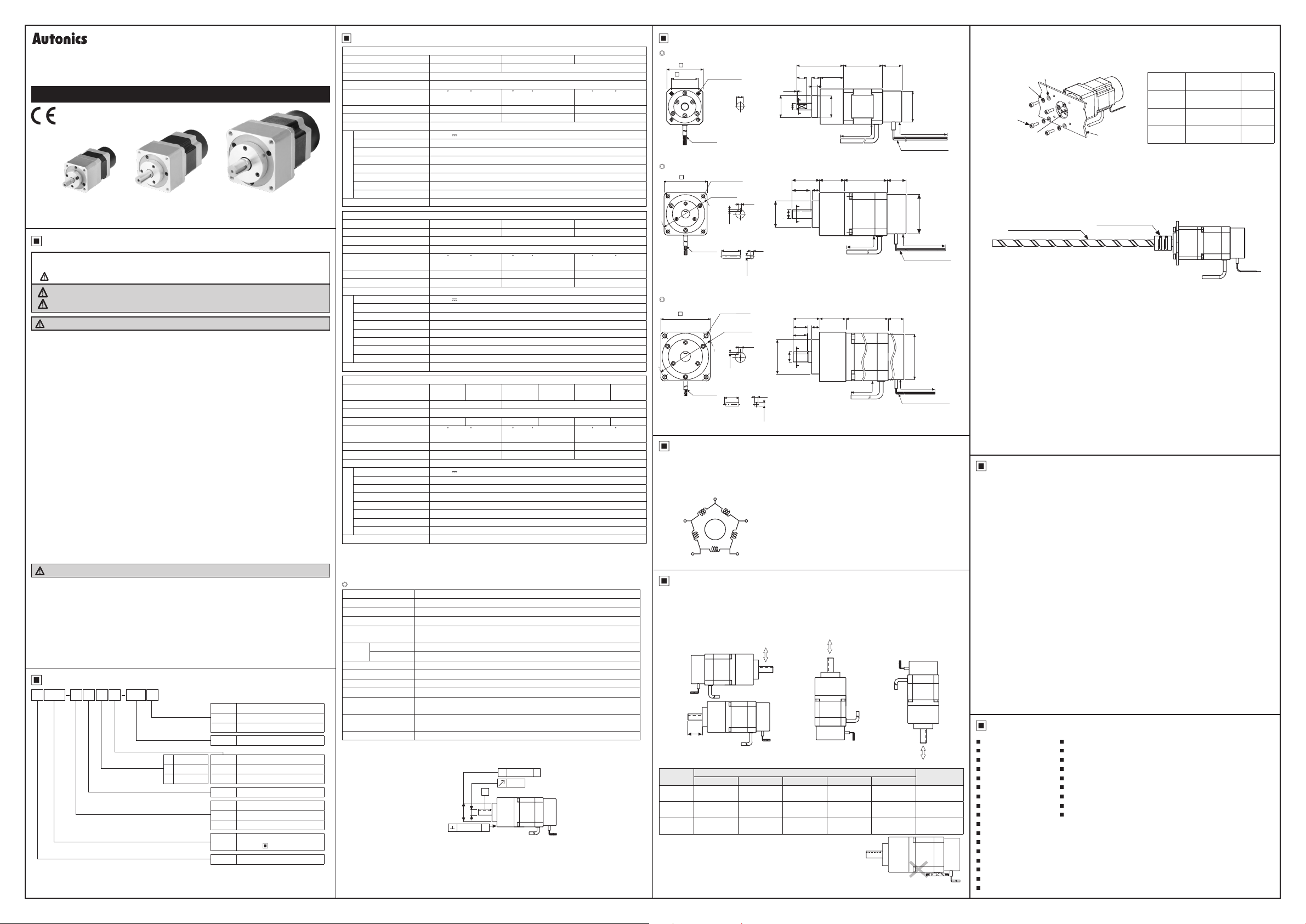
use flexible coupling as image showing above. If the center of the load and the shaft is not aligned,
it may cause severe vibration, damage on shaft or shortened life cycle of bearings.
4. Installation condition
Install the motor in a place that meets certain conditions specified below.
t may cause product damage if instructions are not following.
①
The inner housing installed indoor
(This unit is manufactured and designed for attaching to equipment. Install a ventilation device.)
②
Within -10 to 50
③
Within 35 to 85%RH (at non-dew status) of ambient humidity
④
The place without explosive, flammable and corrosive gas
⑤
The place without direct ray of light
⑥
The place where dust or metal scrap does not enter into the unit
⑦
The place without contact with water
⑧The place without contact with strong alkali or acid material
⑨
The place where easy heat dissipation could be made
⑩
The place where no continuous vibration or severe shock
⑪
The place with less salt content
⑫
The place with less electronic noise occurs by welding machine, motor
⑬
The place where radioactive substances and magnetic fields does not exist and is not in the
vacuum status
Loo-----
Flat washer
Mounting plate
.
※
Use Autonics flexible coupling (ERB Series).
Ball screw or TM screw
℃ (at non-freezing status) of ambient temperature
Flexible coupling
, oil, or other liquid
Motor size
Frame size
42mm
Frame size
60mm
Frame size
85mm
The thickness of
mounting plate
Min. 5mm M4
Min. 8mm M5
Min. 12mm M8
, etc.
Using bolt
Cautions during Use
1. Follow instructions in 'Cau ions during Use'.
Otherwise, It may cause unexpected accidents.
2. Using motors at low temperature may cause reducing ball bearing's grease and gear part
consistency and friction torque is increased.
Start he motor in a steady manner since motor's torque is not to be influenced.
3. When power is supplied or not to the brake, the unit may occur clack sound.
4. When drive the motor
When the brake pad is worn out, the product life cycle is shorten, the rated static friction
, supply power to electro-magne ic brake for releasing he brake.
torque is reduced.
5. Be careful of backlash when positioning the motors in both CW/CCW directions.
Geared type stepper motor use the high accuracy gear for positioning and it realizes low
backlash. However, when posi ioning the motor in both CW/CCW directions, it may cause
problem.
Therefore, make sure that motor positioning will be made in one single direction in case of
geared type motors.
6. For using motor, it is recommended to maintenance and inspec ion regularly.
Unwinding bolts and connection parts for the unit installation and load connection
①
Strange sound from ball bearing of the unit
②
Damage and stress of lead cable of he unit
③
Connection error with driver
④
Inconsistency between the axis of motor output and he center, concentric (eccentric,
⑤
declina ion) of the load, etc.
7. This unit may be used in the following environments.
Indoors (in the environment condition rated in 'Specifications')
①
Altitude max. 2,000m
②
Pollution degree 2
③
Installation category II
④
Major Products
Photoelectric Sensors Temperature Controllers
Fiber Optic Sensors Temperature/Humidity Transducers
Door Sensors SSRs/Power Controllers
Door Side Sensors Counters
Area Sensors Timers
Proximity Sensors Panel Meters
Pressure Sensors Tachometer/Pulse (Rate) Meters
Rotary Encoders Display Units
Connector/Sockets Sensor Controllers
Switching Mode Power Supplies
Control Switches/Lamps/Buzzers
/O Terminal Blocks & Cables
Stepper Motors/Drivers/Motion Controllers
Graphic/Logic Panels
Field Network Devices
Laser Marking System (Fiber, CO₂, Nd: YAG)
Laser Welding/Cutting System
■
■
■
■
■
■
■
■
■
DR W170418 AB
 Loading...