

DRW171378AC
Autonics
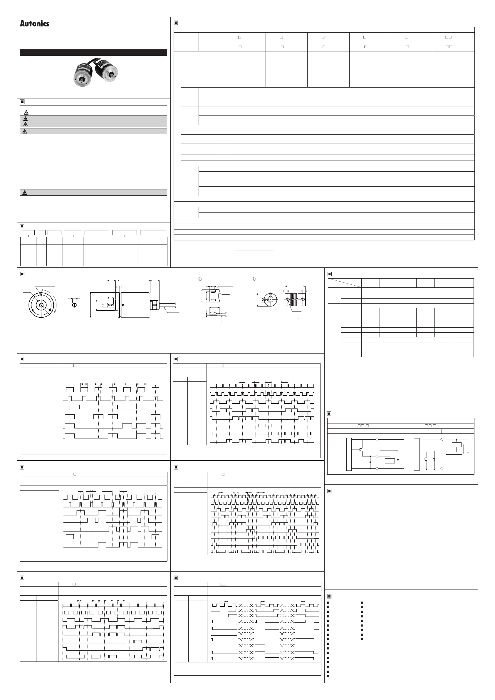
Ø60mm Shaft type Single-turn
Absolut Rotart Encoder
ENP SERIES
I N S T R U C T I O N M A N U A L
Please read the following safety considerations before use.
Safety Considerations
00
Please observe all safety considerations for safe and proper product operation to avoid hazards.
※
symbol represents caution due to special circumstances in which hazards may occur.
※
Warning
Caution
Warning
1. Fail-safe device must be installed when using the unit with machinery that may cause
serious injury or substantial economic loss. (e.g. nuclear power control, medical equipment,
ships, vehicles, railways, aircraft, combustion apparatus, safety equipment, crime/disaster
prevention devices, etc.)
Failure to follow this instruction may result in personal injury, economic loss or re.
2. Do not use the unit in the place where ammable/explosive/corrosive gas, high humidity,
direct sunlight, radiant heat, vibration, impact, or salinity may be present.
Failure to follow this instruction may result in explosion or re.
3. Install on a device panel to use.
Failure to follow this instruction may result in re.
4. Do not connect, repair
Failure to follow this instruction may result in re.
5. Check 'Connections' before wiring.
Failure to follow this instruction may result in re.
6. Do not disassemble or modify the unit.
Failure to follow this instruction may result in re.
Caution
1. Use the unit within the rated specications.
Failure to follow this instruction may result in re or product damage.
2. Do not short the load.
Failure to follow this instruction may result in product damage by re.
3. Do not use the unit near the place where there is the equipment which generates strong
magnetic force or high frequency noise and strong alkaline, strong acidic exists.
Failure to follow this instruction may result in product damage.
Ordering Information
00
ENP - 1 1 1 R - 360 - P
Series
Ø60mm
(Shaft
diameter
: Ø10mm)
Dimensions
Ø48
Output Waveform (6 division) Output Waveform (16 division)
00 00
Model ENP-111 -006-P
Shaft revolution angle( ) 0 60 120 180 240 300 360
Output value 6 1 2 3 4 5 6
Wire color Wire function
Black
Gray
Brown
Red
Orange
White
● TP1=53 ±30', TP2=15 ±30' ● P>TS(56 )>TP1 ● P=60 ±30'
Above waveform is based on the positive logic.
(The ouput waveform of negative logic is opposite to above waveform.)
00 00
Model ENP-111 -008-P
Shaft revolution angle( ) 0 45 90 135 180 225 270 315 360
Output value 8 1 2 3 4 5 6 7 8
Wire color Wire function
Black
Gray
Brown
Red
Orange
Yellow
White
● TP1=39 ±30', TP2=15 ±30' ● P>TS(42 )>TP1 ● P=45 ±30'
Above waveform is based on the positive logic.
(The ouput waveform of negative logic is opposite to above waveform.)
Output Waveform (12 division) Output Waveform (360 division)
00 00
Model ENP-111 -012-P
Shaft revolution angle( ) 0 30 60 90 120 150 180 210 240 270 300 330 360
Output value 12 1 2 3 4 5 6 7 8 9 10 11 12
Wire color Wire function
Black
Gray
Brown
Red
Orange
Yellow
Green
White
● TP1=3 ±30', TP2=15 ±30' ● P>TS(26 )>TP1 ● P=30 ±30'
Above waveform is based on the positive logic.
(The ouput waveform of negative logic is opposite to above waveform.)
※
The above specications are subject to change and some models may be discontinued without notice.
※
Be sure to follow cautions written in the instruction manual, and the technical descriptions (catalog, website).
Thank you for choosing our Autonics product.
Failure to follow these instructions may result in serious injury or death.
Failure to follow these instructions may result in personal injury or product damage.
, or inspect the unit while connected to a power source.
Output
Output
code
method
0
: Negative
BCD
logic
code
1
: Positive
logic
3-M4 DP 10
TP1
TP2
0
BCD(2
1
BCD(2
2
BCD(2
EP(Parity)
TP1
TP2
BCD(20)
BCD(21)
BCD(22)
BCD(23)
EP(Parity)
TP1
TP2
0
)
BCD(2
1
)
BCD(2
2
)
BCD(2
3
)
BCD(2
BCD(20×10)
EP(Parity)
Power supply Rotating direction
0: 5VDC
±5%
1: 12-24VDC
±5%
3-120°
0
9
-0.01
lf
□
H
L
H
L
H
)
L
H
)
L
H
)
L
H
L
□
H
L
H
L
H
L
H
L
H
L
H
L
H
L
□
H
L
H
L
H
L
H
L
H
L
H
L
H
L
H
L
F: Output value
increase at
CW direction
R: Output value
increase at
CCW direction
Ø60
TP1
TP2 TSP
TP1
TP1 TP2 TSP
Resolutions/
revolution
006: 6 division
008: 8 division
012: 12 division
016: 16 division
024: 24 division
360: 360 division
15
0
-0.021
0 02
0.005
Ø10
Ø25
TP2 TSP
Control output
N: NPN open
collector output
P: PNP open
collector output
77 22.520
6
4 3
Specications
Type Ø60mm shaft type Single-turn Absolute Rotary encoder
Model
Resolution 6 division 8 division 12 division 16 division 24 division 360 division
Output phase
Output angle
Control
output
Response
time
Max. response
Electrical specication
frequency
Power supply 5VDCᜡ ±5% (ripple P-P: max. 5%), 12-24VDCᜡ ±5% (ripple P-P: max. 5%)
Current consumption Max. 100mA (disconnection of the load)
Insulation resistance Over 100MΩ (at 500VDC megger between all terminals and case)
Dielectric strength 750VAC 50/60Hz for 1 minute (between all terminals and case)
Connection Axial cable type
Mechanical
specication
Vibration 1.5mm amplitude at frequency of 10 to 55Hz in each X, Y, Z direction for 2 hours
Shock Approx. max. 75G
Environment
Protection structure IP50 ( EC standard)
Cable
Accessory Mounting bracket, coupling
Weight
※
1: Make sure that max. response revolution should be lower than or equal to max. allowable revolution when selecting the resoultion.
[Max. response revolution (rpm) =
※
2: The weight includes packaging. The weight in parentehsis is for unit only.
※
Environment resistance is rated at no freezing or condensation.
Ø8, 1m
Model ENP-111 -016-P
Shaft revolution angle( )
Output value
Wire color
Black
Gray
Brown
Red
Orange
Yellow
Green
White
● TP1=2 ±30', TP2=11.25 ±30' ● P>TS(19 5 )>TP1 ● P=22 5 ±30'
Above waveform is based on the positive logic.
(The ouput waveform of negative logic is opposite to above waveform.)
PNP open
collector output
NPN open
collector output
PNP open
collector output
NPN open
collector output
PNP open
collector output
NPN open
collector output
Starting torque Max. 500gf.cm (0 05N.m)
Moment of
inertia
Shaft loading Radial: 10kgf, Thrust: 2 5kgf
Mechanical
revolution
Ambient temp. -10 to 70℃, storage: -25 to 85
Ambient humi. 35 to 85%RH, storage: 35 to 90%RH
2
※
ENP-111
-006-P ENP-111 -008-P ENP-111 -012-P ENP-111 -016-P ENP-111 -024-P ENP-11 -360-P
□
-006-N ENP-101 -008-N ENP-101 -012-N ENP-101 -016-N ENP-101 -024-N ENP-10 -360-N
ENP-101
□
TP (Timing Pulse): 2 bit
TS (Signal Pulse): 4 bit
TP1: 53 ±30'
TP2: 15 ±30'
P: 60 ±30'
TS: 56 ±30'
Output voltage: min. (Power voltage-1.5)VDCᜡ, load current: max. 32mA
Load current: max. 32mA, residual voltage: max. 1VDC
T
=800ns, T
ON
=800ns, T
T
ON
20kHz
Max. 300g cm
3,600rpm
1
※
Ø8mm, 12-wire, 1m, Double shield cable (AWG 24, core wire diameter: 0 08mm, number of cores: 40, insulator diameter: Ø1mm)
Approx. 478g (Approx. 400g)
Max. response frequency
Bracket
7
5
2-R2.1
R27
20
24
15
2
5.5
3.5
※
Do not load overweight on the shaft.
※
Do not put strong impact when insert a coupling into shaft.
Failure to follow this instruction may result in product damage.
※
Fix the unit or a coupling by a wrench under 0.15 N.m of torque.
※
When you install this unit, if eccentricity and deection angle are larger,
it may shorten the life cycle of this unit.
□
0 22.5 45 67.5 90 112.5 135 157.5 180
16 1 2 3 4 5 6 7 8 9 10 11 12 13 14 15 16
H
L
H
L
H
L
H
L
H
L
H
L
H
...__._...;.......,._..,_...,.._.,_...,..
L
H
L
TP1 TP2
Wire function
TP1
TP2
0
)
BCD(2
1
)
BCD(2
2
)
BCD(2
3
)
BCD(2
BCD(20×10)
EP(Parity)
30
OFF
OFF
2
(3×10⁻⁵kg.m2)
Resolution
Output Waveform (24 division) Output Waveform (8 division)
Model ENP-111 -024-P
Shaft revolution angle( )
Output value
Wire color
Wire function
Black
TP1
Gray
TP2
0
BCD(2
1
BCD(2
2
BCD(2
3
BCD(2
BCD(20×10)
1
×10)
BCD(2
EP(Parity)
( )
0
BCD(2
1
BCD(2
2
BCD(2
3
BCD(2
BCD(20×10)
1
BCD(2
×10)
2
BCD(2
×10)
3
BCD(2
×10)
0
BCD(2
×100)
1
BCD(2
×100)
)
)
)
)
)
)
)
)
Brown
Red
Orange
Yellow
Green
Blue
White
● TP1=8 ±30', TP2=3 ±30' ● P>TS(11 )>TP1 ● P=15 ±30'
Above waveform is based on the positive logic.
(The ouput waveform of negative logic is opposite to above waveform.)
Model ENP-11 -360-P
Shaft revolut on angle
Output value
Wire color Wire function
Black
Brown
Red
Orange
Yellow
Green
Blue
Violet
Gray
White
● TS=1 ±30'
Above waveform is based on the positive logic.
(The ouput waveform of negative logic is opposite to above waveform.)
□
0
15 30 45 60 75 90
24 1 2 3 4 5 6 7 8 9 10 11 12 13 14 15 16 17 18 19 20 21 22 23
H
L
H
L
H
L
H
L
H
L
H
L
H
L
H
L
H
L
DD
0
1 2 3 4 5 · · · · ·
0
1 2 3 4 5 · · · · ·
H
L
1...f"l.....H..x:
H
_____f'"""""'l.
L
H
_______r----x:
L
H
.__
___
L
H
.__
___
L
H
_____
L
H
.__
___
L
H
_____
L
H
,.__
____
L
H
,
L
105 120 135 150 165 180 195 210 225 240 255 270 285 300 315 330 345 360
TP1
TP2 TSP
TS TS TS
14+:
X:
:x
:x
:x
x:
:x
x::x~x==x
x::x
x::x
x::x~x::x
x::x~x==x
x-
-x
□
□
TP (Timing Pulse): 2 bit
(BCD,EP)
=max. 800ns (Cable length: 1m, I sink = 32mA)
=max. 800ns (Cable length: 1m, I sink = 32mA)
TS (Signal Pulse): 5 bit
TP1: 39 ±30'
TP2: 15 ±30'
P: 45 ±30'
TS: 42 ±30'
℃
(BCD,EP)
TP (Timing Pulse): 2 bit
TS (Signal Pulse): 6 bit
TP1: 3 ±30'
TP2: 15 ±30'
P: 30 ±30'
TS: 26 ±30'
ᜡ
× 60 sec]
Coupling
+0 1
0
Ø22
Ø10
3.4
(unit: mm)
25
3.4
4-M4
● Parallel misalignment: max. 0 25mm
● Angular misalignment: max. 5
● End-play: max. 0.5mm
202 5 225 247.5 270 292.5 315 337.5 360
P
TS
ry'-+----+----+----+----+----+----,
___
.......,
198 199 200 201 202
198 199 200 201 202
L.H.__s-u-x:
7....__________
.__
..r,___x:
_____
____
~
__
· · · · ·
· · · · ·
:xL.rL.ru
X:
:XJ""""""1...__
_.
x:
=x~
:x_______r--,_
x::x
x::x
356 357 358 359 360
356 357 358 359 0
:....-:
____
___
______,----x-
-x---~L
□
□
(BCD,EP)
Connections
00
Resolution
Wire color
~
White
Power
Black
wire
Shield wire F.G.
Black TP1
Brown 2
Red 2
Orange 2
Yellow N.C 2
Output
Green N.C N.C 2
wire
Blue N.C N.C N.C N.C 2
Purple N.C 2
Gray TP2
White
□
□
TP (Timing Pulse): 2 bit
TS (Signal Pulse): 6 bit
TP1: 2 ±30'
TP2: 11.25 ±30'
P: 22.5 ±30'
TS: 19.5 ±30'
(BCD,EP)
□
□
TP (Timing Pulse): 2 bit
TS (Signal Pulse): 7 bit
TP1: 8 ±30'
TP2: 3 ±30'
P: 15 ±30'
TS: 11 ±30'
(BCD,EP)
TS (Signal Pulse): 10 bit
TS: 1 ±30'
6 division 8 division 12 division 16 division 24 division 360 division
1
※
+V
1
※
GND(0V)
2
※
0
1
2
EP(Parity)
0
2
1
2
2
2
3
2
※
3
※
0
2
1
2
2
2
3
2
0
0
2
2
2
2
2
1
2
2
2
3
2
×10 20×10 20×10 21×10
Shield wire F.G.
※1: Insulator external diameter is
2:
※
TP1/TP2
Because low resolution model has long output signal period, this signal for enable is easy
to determine signal recognization point about output.
3:
※
EP
Parity signal. It outputs odd parity.
※
Unused wire must be insulated.
※
Encoder case and shield wire must be grounded.
※
N C: Not Connected.
※
Output cable must not be short-circuited, because Driver IC is used in output circuit.
※
Do not apply tensile strength over 30N to the cable.
Control Output Diagram
00
Ø1 5mm.
Output PNP open colloector output NPN open collector output
Model ENP-11
Item Encoder circuit Load connection Encoder circuit Load connection
- -
P ENP-10
□□□
- -
□□□
+V
Source current
Output
circuit
Main circuit
※
The output circuit of each output signal is the same.
24
Cautions during Use
00
1. Follow instructions in 'Cautions during Use'. O herwise, It may cause unexpected
accidents.
2. 5VDC, 12-24VDC power supply should be insulated and limited voltage/current or
Class 2, SELV power supply device.
3. For using the unit wi h the equipment which generates noise (switching regulator,
inverter, servo motor, etc.), ground the shield wire to the F.G. terminal.
4. Ground the shield wire to he F.G. terminal.
5. When using switching mode power supply, frame ground (F.G.) terminal of power
supply should be grounded.
6. Wire as short as possible and keep away from high voltage lines or power lines,
to prevent induc ive noise.
7. Check the wire type and response frequency when extending wire because of
distortion of waveform or residual voltage increment etc by line resistance or capacity
between lines.
8. This unit may be used in he following environments.
Indoors (in the environment condition rated in 'Specications')
①
Altitude max. 2,000m
②
Pollution degree 2
③
Installa ion category II
④
Main Products
00
Photoelectric Sensors Temperature Controllers
■
Fiber Optic Sensors Temperature/Humidity Transducers
■
Door Sensors SSRs/Power Controllers
■
Door Side Sensors Counters
■
Area Sensors Timers
■
Proximity Sensors Panel Meters
■
L
Pressure Sensors Tachometer/Pulse (Rate) Meters
■
_
Rotary Encoders Display Units
■
Connector/Sockets Sensor Controllers
■
L
Switching Mode Power Supplies
■
_
Control Switches/Lamps/Buzzers
■
I/O Terminal Blocks & Cables
■
Stepper Motors/Drivers/Motion Controllers
■
Graphic/Logic Panels
■
Field Network Devices
■
Laser Marking System (Fiber, CO₂, Nd: YAG)
■
Laser Welding/Cutting System
■
■
■
■
■
■
■
■
■
■
: max. 32mA
Output
~~
0V
Load
+
-
.......-.-ri-~
Main circuit
□□
□□
0
1
2
3
1
1
2
2
2
3
2
20×10
×10 22×10
3
0
2
20×100
21×100
N
+V
Load
Output
Sink current
: mx. 32mA
0V
DRW171378A C
×10
+
-
 Loading...