

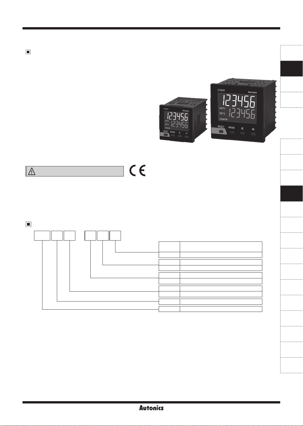
CX Series
DIN W48×H48mm, W72×H72mm LCD Display Counter/Timer
Features
Improved vis bility with LCD display
●
Input method: voltage input (PNP)/no-voltage input (NPN) selectable model (by parameter setting),
●
Setting range of one-shot output time: 0.01 sec to 99.99 sec by 0.01 sec unit
●
Mounting space saving with compact design (back length: 64.5mm)
●
Free voltage input model
SENSORS
CONTROLLERS
MOTION DEVICES
[Counter]
Setting range of prescale value: 0.00001 to 99999.9
●
Various input/output mode (input: 11 types, output: 11 types)
●
Start point (counting value reset) setting
●
TOTAL counter display mode
●
: Displays the present value and the integrated value
simultaneously.
[Timer]
Various output mode (15 types)
●
Wide time setting range: 0.001 sec to 99999.9 hour
●
'0' time setting function
●
Please read “Safety Considerations”
in the instruction manual before using.
~1&
____
1(€
Ordering Information
CX 1P 4
6 S
Display digit
Item
-
Output
Size
F
Signal input me hod
Power supply
No mark
F Free voltage input
2 24VAC 50/60Hz, 24-48VDC
4 100-240VAC 50/60Hz
1P 1-stage setting
2P 2-stage setting
S DIN W48×H48mm
M DIN W72×H72mm
6 999999 (6-digit)
CX LCD Display counter/Timer
Voltage input (PNP)/no-voltage input (NPN)
selectable type
SOFTWARE
(J)
Temperature
Controllers
(K)
SSRs
(L)
Power
Controllers
(M)
Counters
(N)
Timers
(O)
Digital
Panel Meters
(P)
Indicators
(Q)
Converters
(R)
Digital
Display Units
(S)
Sensor
Controllers
(T)
Switching
Mode Power
Supplies
(U)
Recorders
Autonics
M-41
(V)
HMIs
(W)
Panel PC
(X)
Field Network
Devices
CX Series
Specications
Model CX6 S-1P
Display digits 6-digit
Display method
Character
size (W×H)
Power
supply
Counting value 4.1×10.1mm 6.2×15.2mm
Setting value 3 . 3×8 .1m m 5×12.3mm
AC voltage 100 -240VACᜠ 50/60Hz
AC/DC voltage 24VACᜠ 50/60Hz, 24-48VDC
7-segment (1st, 2nd digits of counting value display: white, setting value display: green) LCD method,
11-segment (the other digits of counting value display: white) LCD method,
Operation display part: yellow LCD method
□□ □□ □□ □□
CX6S-2P
Permissible voltage range 90 to 110% of rated voltage
CX6
AC voltage
AC/DC
Power
voltage
consumption
Max. IN A/
INB counting
speed
- Max. 6.4VA Max. 6.7VA M a x. 7.1 VA M a x . 7. 5VA
□□□
- F Max. 4.2VA Max. 4. 9VA Ma x. 4 .7VA M ax. 5.4VA
CX6
□□□
AC: max. 5.5VA
-
CX6
□□□
DC: max. 3.5W
CX6
CX6
CX6
AC: max. 3.6VA
- F
□□□
DC: max. 2.5W
- Selectable among 1cps/30cps/300cps/1kcps/5kcps
□□□
- F 20cps
□□□
AC: max. 5.6VA
DC: max. 3.6W
AC: max. 4.0VA
DC: max. 2.8W
Counting range -99999 to 999999
Scale Decimal point up to f th digit
Counter
Min. signal
width
Time range
CX6
- RESET, TOTAL RESET signal: selectable among 1ms/20ms
□□□
- F RESET signal: 25ms
CX6
□□□
999.999s, 9999.99s, 99999.9s, 999999s, 99m 59.99s, 999m 59.9s, 9999m 59s, 99999.9m, 999999m,
99h 59m 59s, 9999h 59m, 99999.9h
Operation mode Up, Down
CX6
Min. signal
width
Timer
Repeat error
Set error
Voltage error
Temp. error
Input method
- INA, I NHI B IT, RESET, TOTAL RESET signal: selectable among 1ms/20ms
□□□
- F INA, INH, RESET signal: 25ms
CX6
CX6
CX6
□□□
-
□□□
- F
□□□
- ]- In case of power ON start: max. ±0.01% ±0.05s
[CX6
□
□□
[CX6
Selectable among voltage input (PNP)/no-voltage input (NPN)
[Voltage input (PNP)]-input impedance: 10.8kΩ, [H]: 5-30VDCᜡ, [L]: 0-2VDC
[No-voltage input (NPN)]-short-circuit impedance: max. 1kΩ, short-circuit residual voltage: max. 2VDC
[Free voltage input]- INA (START) , INB (INHIBIT) input
[No-voltage input]- RESET input, shor t-circuit impedance: max. 1kΩ, short-circuit residual voltage: ma x. 2V
In case of signal ON start: max. ±0.01% ±0.03s
- F]- In case of power ON start: max. ±0.01% ±0.08s
□
□□
In case of signal ON start: max. ±0.01% ±0.06s
[H]: 24-240VDCᜡ/24-240VACᜠ 50/60Hz, [L]: 0-10VDC/VAC
One-shot output time 0.01 to 99.99s setting
Typ e SPDT (1c): 1 SPST (1a): 2 SPDT (1c): 1 SPDT (1c): 2
Contact
Control
output
Exter nal power supply
Capacity Max. 25 0VACᜠ 3A, 30VDCᜡ 3A resistive load
Typ e
Solid
state
Capacity Max. 30VDCᜡ 100m A
-
1
※
Max. 12VDCᜡ ±10%, 10 0mA
Memory retention Approx. 10 years (non-volatile memory)
Insulation resistance Over 100MΩ (at 500VDC megger)
Dielectric strength 3,000VAC 50/60Hz for 1 min
Noise
immunity
Vibration
Shock
Relay life
cycle
AC voltage Square -wave noise by noise simulator (pulse width 1㎲) ±2kV
AC/DC voltage Square -wave noise by noise simulator (pulse width 1㎲) ±500V
Mechanical 0.75mm amplitude at frequency 10 to 55Hz (for 1 min) in each X, Y, Z direction for 1 hour
Malfunction 0.5mm amplitude at frequency 10 to 55Hz (for 1 min) in each X, Y, Z direction for 10 min
Mechanical 300m/s² (approx. 30G) in each X, Y, Z direction for 3 times
Malfunction 100m/s² (approx. 10G) in each X, Y, Z direction for 3 times
Mechanical Min. 5,000,000 operations
Malfunction Min. 100,000 operations
Protection structure Front par t: IP50 (IEC standard)
Environ-
ment
Approval
2
※
Weight
※
1: This is for the voltage input (PNP)/no-voltage input (NPN) selectable model (CX6
※
2: The weight includes packaging. The weight in parenthesis is for unit only.
※
Environment resistance is rated at no freezing or condensa ion.
Ambient temp. -10 to 55℃, storage: -25 to 65
Ambient humi. 35 to 85%RH, storage: 35 to 85%RH
CE
-
Approx. 157g (approx. 112g) Approx. 162g (approx. 117g) Approx. 235g (approx. 170g) Approx. 240g (approx. 175g)
□□□
Approx. 155g (approx. 110g) Approx. 160g (approx. 115g) Approx. 233g (approx. 168g) Approx. 238g (approx. 173g)
□□□
-
Approx. 156g (approx. 111g) Approx. 161g (approx. 116g) Approx. 234g (approx. 169g) Approx. 239g (approx. 174g)
□□□
Approx. 154g (approx. 109g) Approx. 159g (approx. 114g) Approx. 232g (approx. 167g) Approx. 237g (approx. 172g)
□□□
AC voltage
AC/DC
voltage
CX6
CX6 - F
CX6
CX6 - F
ᜡ
℃
CX6 M-1P
AC: max. 6.2VA
DC: max. 4W
AC: max. 3.9VA
DC: max. 2.9W
CX6M-2P
AC: max. 6.3VA
DC: max. 4.1W
AC: max. 4.5 VA
DC: max. 3.3W
NPN open c ollector: 1 NPN open collector: 2
- ).
□□□
M-42
Autonics
LCD Display Counter/Timer
Connections
CX6S Series
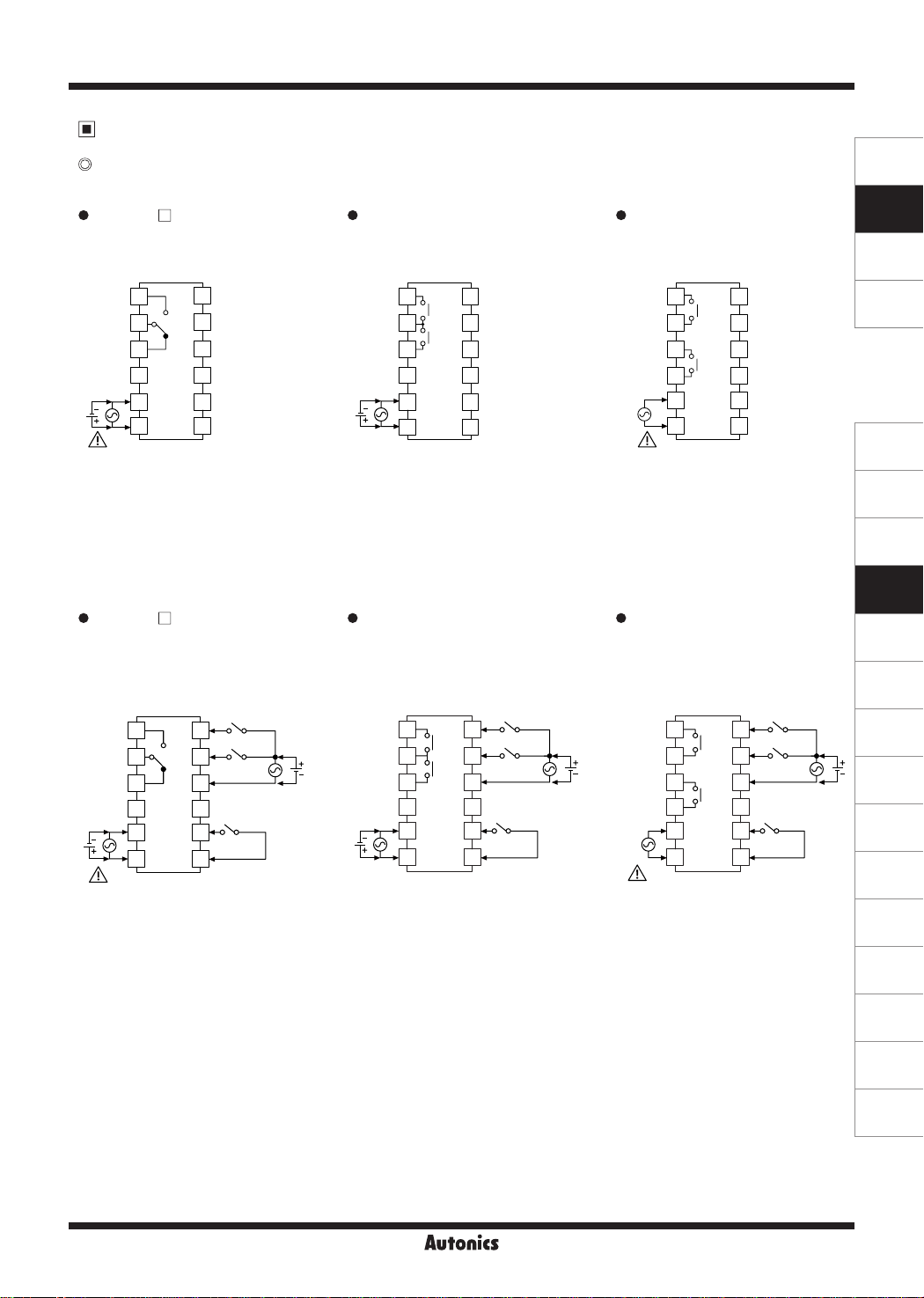
1. Voltage input (PNP), no-voltage input (NPN) selectable model
CX6S-1P
•
□
CONTACT OUT:
250VAC 3A, 30VDC 3A
RESISTIVE LOAD
OUT
7
8
9
10
11
12
※1
SOURCE
1
2
3
4
5
6
:
100-240VAC 50/60Hz 6.4VA
24VAC 50/60Hz 5.5VA
24-48VDC 3.5W
INA
INB/INH
12VDC 100mA
0VDC
RESET
TOTAL RESET
CX6S-2P2 CX6S-2P4
• •
CONTACT OUT1/OUT2:
250VAC 3A, 30VDC 3A
RESISTIVE LOAD
OUT2
OUT1
7
INA
8
INB/INH
9
12VDC 100mA
10
0VDC
11
RESET
12
TOTAL RESET
1
2
3
4
5
6
SOURCE:
24VAC 50/60Hz 5.6VA
24-48VDC 3.6W
CONTACT OUT1/OUT2:
250VAC 3A, 30VDC 3A
RESISTIVE LOAD
OUT2
OUT1
7
INA
INB/INH
8
9
12VDC 100mA
0VDC
10
RESET
11
12
TOTAL RESET
1
2
3
4
5
6
SOURCE:
100-240VAC 50/60Hz 6.7VA
SENSORS
CONTROLLERS
MOTION DEVICES
SOFTWARE
(J)
Temperature
Controllers
(K)
SSRs
(L)
Power
Controllers
2. Free voltage input model
CX6S-1P F CX6S-2P2F CX6S-2P4F
•
CONTACT OUT
: 250VAC 3A, 30VDC 3A
RESISTIVE LOAD
SIGNAL INPUT
: 24-240VAC 50/60Hz, 24-240VDC
※1
SOURCE
□
1
2
3
4
5
6
: 100-240VAC 50/60Hz 4 2VA
7
INA
8
INB/INH
9
OUT
10
11
RESET
12
0VDC
24VAC 50/60Hz 3.6VA
24-48VDC 2.5W
INPUT
•
CONTACT OUT1/OUT2
: 250VAC 3A, 30VDC 3A
RESISTIVE LOAD
SIGNAL INPUT
: 24-240VAC 50/60Hz, 24-240VDC
SOURCE
OUT2
1
2
3
4
5 11
6 12
OUT1
7
8
9
10
INA
INB/INH
RESET
0VDC
: 24VAC 50/60Hz 4.0VA
24-48VDC 2.8W
INPUT
CONTACT OUT1/OUT2
: 250VAC 3A, 30VDC 3A
RESISTIVE LOAD
SIGNAL INPUT
: 24-240VAC 50/60Hz, 24-240VDC
1
2
3
4
5 11
6 12
SOURCE: 100-240VAC 50/60Hz 4.9VA
OUT2
OUT1
7
8
9
10
INA
INB/INH
RESET
0VDC
INPUT
(M)
Counters
(N)
Timers
(O)
Digital
Panel Meters
(P)
Indicators
(Q)
Converters
(R)
Digital
Display Units
(S)
Sensor
Controllers
(T)
Switching
Mode Power
Supplies
(U)
Recorders
(V)
HMIs
(W)
Panel PC
Autonics
M-43
(X)
Field Network
Devices
CX Series
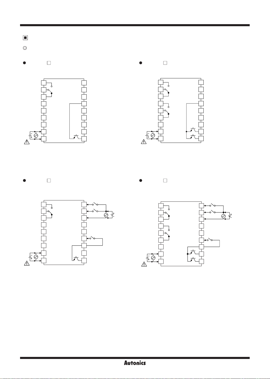
Connections
CX6M Series
1. Voltage input (PNP), no-voltage input (NPN) selectable model
CX6M-1P CX6M-2P
•
CONTACT OUT
※
SOURCE
□
: 250VAC 3A, 30VDC 3A
RESISTIVE LOAD
1
2
OUT
3
4
5
6
7
1
8
9
: 100-240VAC 50/60Hz 7.1VA
24VAC 50/60Hz 6.2VA
24-48VDC 4W
0VDC
SOLID
STAT E
OUT:
30VDC
100mA
10
INA
INB
11
12
12VDC 100mA
13
14
RESET
15
INHIBIT
16
TOTAL RESET
17
18
•
CONTACT OUT1/OUT2
1
※
SOURCE
□
: 250VAC 3A, 30VDC 3A
RESISTIVE LOAD
1
2
OUT2
3
4
OUT1
5
6
SOLID
7
STAT E
OUT:
8
30VDC
9
100mA
: 100-240VAC 50/60Hz 7.5VA
24VAC 50/60Hz 6.3VA
24-48VDC 4.1W
0VDC
OUT1
OUT2
10
11
12
13
14
15
16
17
18
INA
INB
12VDC 100mA
RESET
INHIBIT
TOTAL RESET
2. Free voltage input model
CX6M-1P F CX6M-2P F
•
CONTACT OUT
SIGNAL INPUT: 24-240VAC 50/60Hz, 24-240VDC
※
SOURCE
1: AC voltage type: 100-240VAC 50/60Hz
※
□
: 250VAC 3A, 30VDC 3A
RESISTIVE LOAD
0VDC
10
11
12
13
14
15
16
17
18
INB/INH
RESET
INA
SIGNAL INPUT
1
2
OUT
3
4
5
6
SOLID
7
1
: 100-240VAC 50/60Hz 4.7VA
AC/DC voltage type: 24VAC 50/60Hz, 24-48VDC
STAT E
8
OUT:
30VDC
9
100mA
24VAC 50/60Hz 3.9VA
24-48VDC 2.9W
•
CONTACT OUT1/OUT2
SIGNAL INPUT: 24-240VAC 50/60Hz, 24-240VDC
1
2
3
4
5
6
7
1
※
8
9
SOURCE
: 100-240VAC 50/60Hz 5.4VA
24VAC 50/60Hz 4.5VA
24-48VDC 3.3W
□
: 250VAC 3A, 30VDC 3A
RESISTIVE LOAD
OUT2
OUT1
0VDC
SOLID
STAT E
OUT:
OUT1
30VDC
100mA
OUT2
10
INA
11
INB/INH
12
SIGNAL INPUT
13
14
15
RESET
16
17
18
M-44
Autonics
LCD Display Counter/Timer
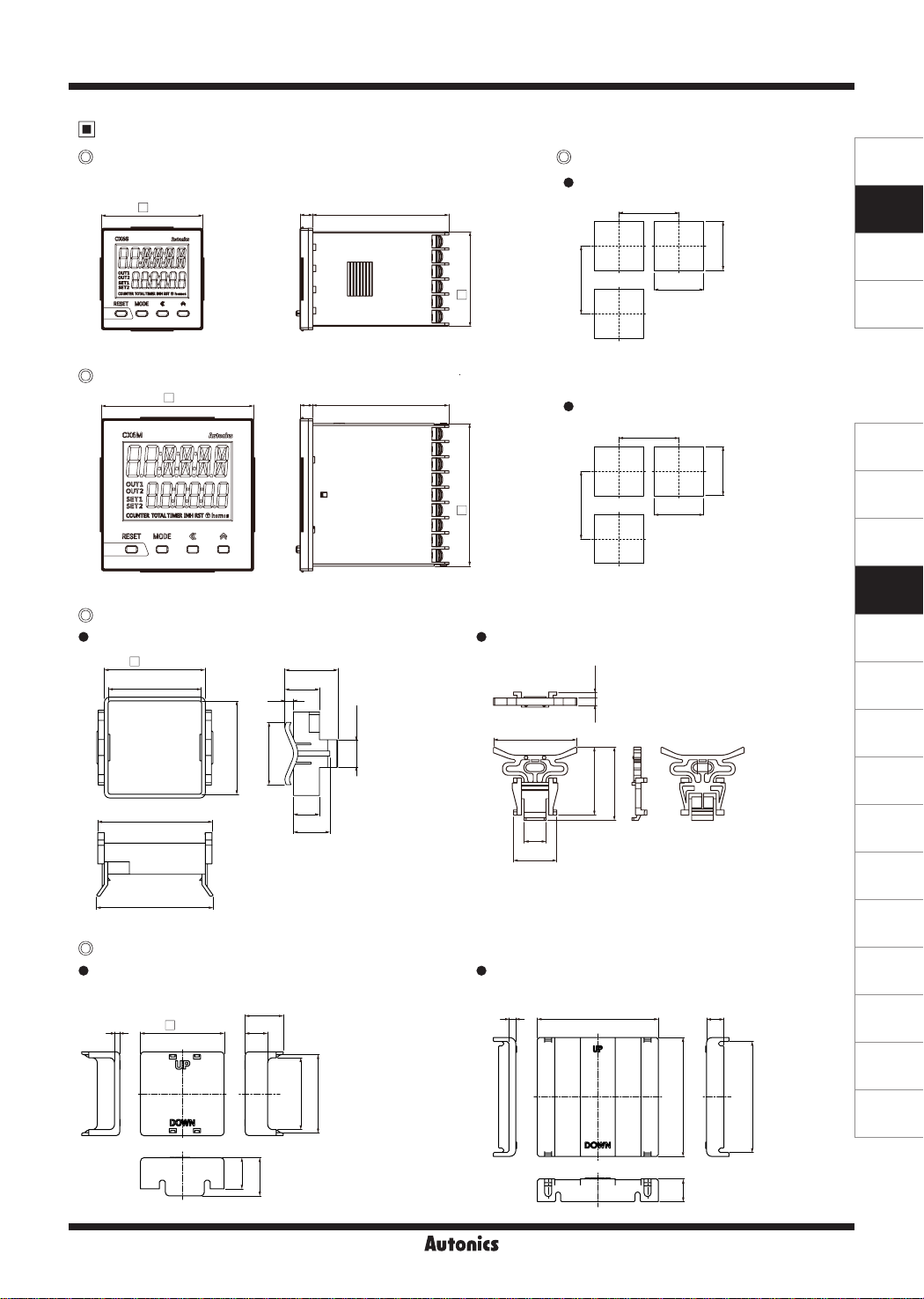
Dimensions
CX6S Series
48 6 64.5
□
0"!00000"!
WJlllJIIIJIIWJ
'
M
~
~
(Q)
CX6M Series
(Q)
Bracket
CX6S Series
•
(Q)
Terminal cover (sold separately)
CX6S Series
•
(RSA-COVER, 48×48mm)
3
-
MOOE C ,-
C C C
72 6 64.5
□
OUTila
ii~1f8BB
COUN1El
'IOfAI.DIIR
Nl11ST
l!lh1m11
±0.2
48.6
□
+0.2
45
0
+0.2
-0.05
44.9
55
56
48.4
22
13
l
b
l
I
IJ
30.6
20
5
36
15
21
I
0
+0.3
16
l
r
?"
=
44.8
=
□
=
I
=
,,,
;,,
=
67.5
;,,
□
;,,
;,,
=
CX6M Series
•
46
12
23.9
CX6M Series
•
(RMA-COVER, 72×72mm)
4
(Q)
Panel cut-out
CX6S Series
•
Min. 65
' '
-EB-----!-------
i i
[
Min. 65
rn
CX6M Series
•
Min. 91
3.3
4
37.5
70
Min. 91
40.5
+0.6
0
1
+0.6
0
45
J
BJ
45
· -
+0.7
0
68
+0.7
68
0
10
(unit: mm)
SENSORS
CONTROLLERS
MOTION DEVICES
SOFTWARE
(J)
Temperature
Controllers
(K)
SSRs
(L)
Power
Controllers
(M)
Counters
(N)
Timers
(O)
Digital
Panel Meters
(P)
Indicators
(Q)
Converters
(R)
Digital
Display Units
(S)
Sensor
Controllers
(T)
Switching
Mode Power
Supplies
(U)
Recorders
(V)
HMIs
B~~B
i
;
i
i
~
..
(W)
Panel PC
41
45
ea D0 IIN
18
22
68.5
,~
13
Autonics
64
M-45
(X)
Field Network
Devices
CX Series
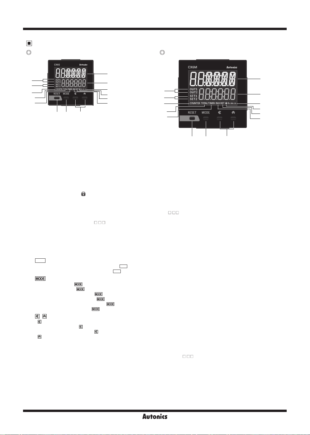
Unit Description
CX6S Series CX6M Series
CX6S Autoaics
7
8
9
10
11
B.HB;B;B.B
gig
BB·ea·BB
~~g
. : : : .
COUml:R
TOTALTIMERINHltST6h:m:s
RESET
MODE
~
12 13 14
« A
1
2
3
4
5
6
0
7
8
9
10
11
1
2
3
4
5
6
12 13 14
1. Counting value display component (white)
RUN mode: Displays counting value for counter operation or time progress value for timer operation.
Function setting mode: Displays parameter.
2. Setting value display component (green)
RUN mode: Displays setting value.
Function setting mode: Displays parameter setting value.
3. Time unit indicator (h:m:s):
4. Key lock indicator ( ):
ii
5. Reset input indicator (RST):
6. INH indicator (INH)
For
the voltage input (PNP)/no-voltage input (NPN) selectable model
(In case of CX6S Series and timer mode, it turns ON for INB/INH signal input.)
For free voltage input model (CX6
7. Output indicator (OUT1, OUT2):
Turns ON for time unit for timer.
Turns ON for key lock setting.
Turns ON for reset key input or reset signal input.
-
F), it turns ON for INB/INH signal input for timer.
□□□
Turns ON for the dedicated control output ON.
8. SV checking and changing indicator (SET, SET1, SET2) (green):
9. COUNTER indicator (COUNTER):
10. TOTAL indicator
1
※
(TOTAL):
11. TIMER indicator (TIMER):
key
1B]
key
Press the
1
※
: Press the
key over 3 sec to enter function setting mode.
~
key to select SV2 (SET2)/SV1 (SET1)/TOTAL counter
~
~
Press the key to save the SV and enter he next setting.
~
~
~
~
RESET
12.
CJ
RUN mode, Function setting mode: Press the
TOTAL counter display mode
13. key
IMODEI
RUN mode: Hold he
Function setting mode: Hold the key over 3 sec to return RUN mode.
Function setting check mode: Hold the key over 1 sec to return RUN mode.
Changing SV mode: Press the
14.
,
~
1) key
~
RUN mode: Press the key to change SV and move SV (SET, SET1, SET2) digits.
Changing SV mode: Press the key to change digits.
2) key
~
Changing SV mode: Increases SV.
Function setting mode: Changes he set ings.
1: This is for the voltage input (PNP)/no-voltage input (NPN) selectable model (CX6
※
Turns ON for counter operation.
In case of TOTAL counter display mode, it turns ON with the COUNTER indicator.
Flashes (progressing time) or Turns ON (stopping time) for timer operation.
RESET
CJ
RESET
key to reset the counting value of TOTAL counter.
CJ
~
key to save SV and return RUN mode.
(CX6
- ), it turns ON for INHIBIT signal input.
□□□
Turns ON when checking and changing SV.
key to reset the counting value and turn OFF the output.
※
1
display for counter operation.
- ).
□□□
M-46
Autonics
LCD Display Counter/Timer
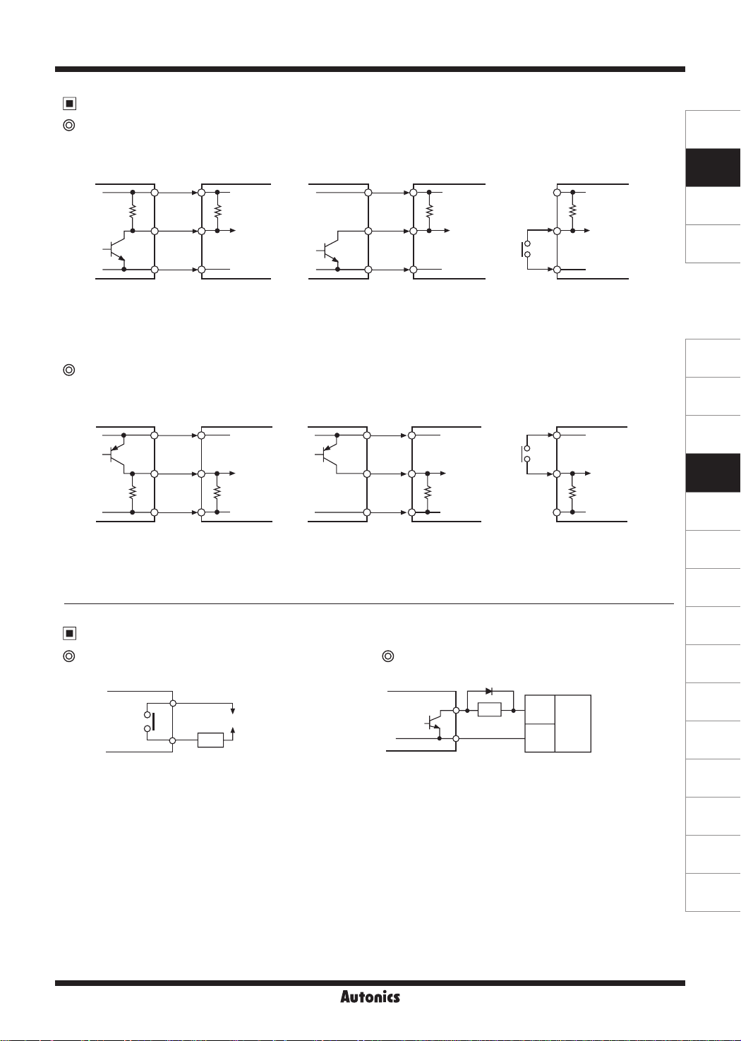
Input Connections
No-voltage input (NPN)
● Solid-state input (standard sensor: NPN output type sensor) ● Contact input
Sensor
Brown Brown
Black Black
Blue Blue
(NPN output) (NPN open collector output)
※
1: CP1, CP2 (INHIBIT), SET input part
※
2: Set counting speed as 1 or 30cps.
Voltage input (PNP)
● Solid-state input (standard sensor: PNP output type sensor) ● Contact input
Sensor
Counter/Timer Counter/Timer Counter/Timer
+12V
5.4kΩ
1
※
Inner circuit
of input part
0V
Brown Brown
Counter/Timer
+12V
Sensor
Sensor
+12V +12V
5.4kΩ 5.4kΩ
※
1
Inner circuit
of input part
※
0V 0V
Counter/Timer Counter/Timer
+12V +12V
※
2
Inner circuit
of input part
2
SENSORS
CONTROLLERS
MOTION DEVICES
SOFTWARE
(J)
Temperature
Controllers
(K)
SSRs
(L)
Power
Controllers
1
※
Black Black
10.8kΩ
Blue Blue
(PNP output)
※
1: CP1, CP2 (INHIBIT), SET input part
※
2: Set counting speed as 1 or 30cps.
Inner circuit
of input part
0V 0V 0V
(PNP open collector output)
1
※
Inner circuit
of input part
10.8kΩ 10.8kΩ
Output Connections
Contact output Solid-state output
Counter/Timer
(Power of load)
Load
※
Select the load which capacity is not over contact
capacity.
Counter/Timer
※
For solid state output, select load power and load not to be over
(max. 30VDC, 100mA), swithching capacity.
※
Do not supply reverse polarity voltage.
※
1: For using inductive load (relay, etc.), connect surge absorber
(diode, varistor etc.) at the bo h ends of load.
※
Load
Inner circuit
of input part
1
(+)
Power
for load
(DC)
-
)
(
(M)
Counters
(N)
Timers
(O)
Digital
Panel Meters
(P)
Indicators
(Q)
Converters
(R)
Digital
Display Units
(S)
Sensor
Controllers
(T)
Switching
Mode Power
Supplies
(U)
Recorders
(V)
HMIs
(W)
Panel PC
Autonics
M-47
(X)
Field Network
Devices
CX Series
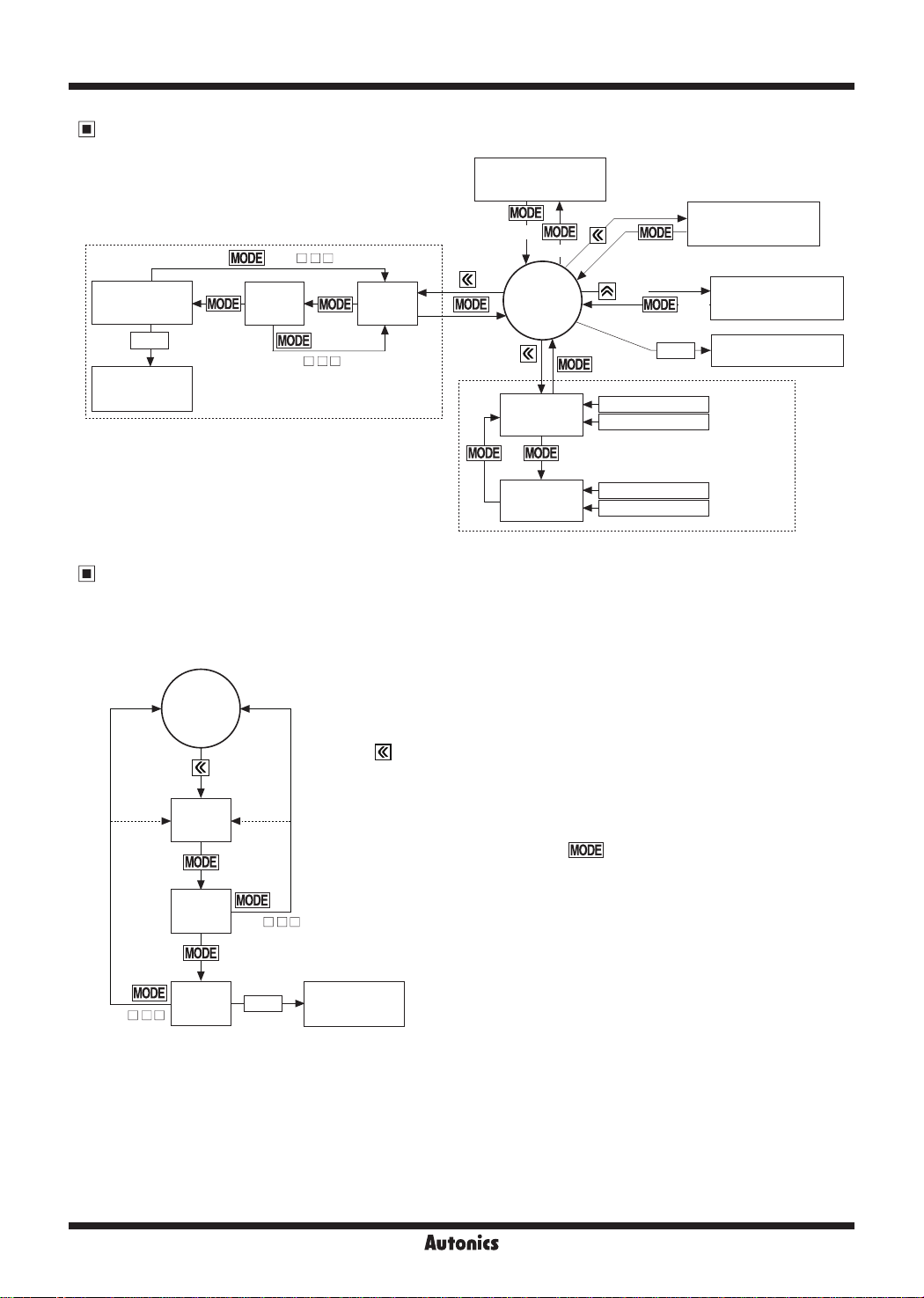
Operations and Functions (counter/timer)
(RUN mode)
TOTAL
counter
RESET
Reset TOTAL
counter
(CX6 - )
IMODEI
SET1
value
□□□
(CX6 - F)
□□□
SET2
value
[Counter]
Function setting
mode
3 sec
RUN mode
(RUN mode)
12:30:25
OU 1
OU 2
SE 2
3
sec
1:25:47
IMER
1 sec
1 sec
RESET
Display PV
Display SET2
Changing
SV mode
Function setting
check mode
-----
PV RESET
12:34:56
OU 1
OU 2
5:43:50
SE 1
IMER
Display PV
Display SET1
[Timer]
Counter mode
●
Changing SV mode
When input signal is ON during changing SV, it operates counting and output control.
It is available to set SV as '0' and the dedicated output for SV '0' occurs.
There are output mode which cannot set SV as '0'. (the setting value display component ashes three times when SV is set as '0')
RUN mode
SET2
value
SET1
value
TOTAL
(CX6 - )
counter
(CX6 - F)
RESET
Press the
When entering changing SV mode, the counting value display component displays the
current value and the setting value display component displays SV.
After setting SV at each parameter, press the
next parameter setting or returns to RUN mode.
key to enter changing SV mode in RUN mode.
key to save SV and it moves
Reset TOTAL
counter
M-48
Autonics

LCD Display Counter/Timer
● Function setting mode
1: In case of free voltage input model (
※
2:
※
This parameter is for the voltage input(PNP)/no-voltage input(NPN) selectable model (CX6 - ).
: When changing the setting of shaded parameters, all output turn OFF.
※
-
:··--------------·----------·----------------
Function setting mode
OUT output time
OUtT
[
]
Q
CX6
RUN mode
3 sec
~
-- ----- ----- -- ----------
Counter/Timer [
Input mode [
~
Output mode [
~
Max. counting speed
~
OUT2 output time [
~
OUT1 output time [
~
Decimal point [DP]
~
~
※
1
※
※
_____
LOCK
Min. reset time
Input logic
Prescale decimal point [
Prescale value [
TOTAL counter
Start Point value [
Memory protection [
,-----------=~=ODE='-'-
Key lock [
- F)
□□□
C-T
nM
I
]
M
OUt
1
※
OUT2
OUT1
1
ESET
R
[
SIG
[
SClDP
SCL
2
TOTAL
[
START
DATA
]
, these parameters do not appear due to xed setting.
- Hold the key over 3 sec in RUN mode and it enters
function setting mode.
- Hold the key over 3 sec in func ion setting mode
and it returns to RUN mode.
]
]
CPS
[
]
~
]
]
]
]
]
]
]
3 sec
-- --
]
]
-
[ml
□□□
SENSORS
CONTROLLERS
MOTION DEVICES
SOFTWARE
(J)
Temperature
Controllers
(K)
SSRs
(L)
Power
Controllers
(M)
Counters
(N)
Timers
(O)
Digital
Panel Meters
(P)
Indicators
● Function setting check mode
-When checking the saved parameters, press the , key to check next item.
- At function setting check mode, the counting value display component displays he parameters and the setting value display
component displays the SV of he parameters.
● Checking SV of TOTAL counter
- At TOTAL counter operation, the counting value display component displays the current value and the setting value display component
displays TOTAL counter counting value.
※When TOTAL counter counting value is over 999999, it counts from 0 again.
(only for free voltage input model (
● Switching display of the setting value display component
(only for voltage input (PNP)/no-voltage input (NPN) selectable model (CX6 - )
- In case of 2-stage setting model(CX6-2P ), whenever pressing the key, each SET2, SET1, TOTAL COUNTER value
displays consecutively.
● Display HOLD output mode for counter
-
It displays the over value of prescale value.
-
When SV is n multiplied by prescale value and the display value after HOLD output mode and
□
□□
CX6
-
F))
□□□
□□□
SV are dierent, the prescale value is not the 1/n time of SV.
● RESET
-In RUN mode, func ion setting mode, press the
- At TOTAL counter display mode, press he
key to reset the current value and the output turns OFF.
RESET
CJ
key to reset TOTAL counter counting value and he current counting value.
RESET
CJ
Autonics
M-49
(Q)
Converters
(R)
Digital
Display Units
(S)
Sensor
Controllers
(T)
Switching
Mode Power
Supplies
(U)
Recorders
(V)
HMIs
(W)
Panel PC
(X)
Field Network
Devices

key: changes parameter setting value)
key: moves parameters,
I
Parameter Setting (Counter)
~
CX Series
: Counter
(
COUNT
※
TIME
!
COUNT
Parameter Parameter setting value
Counter/Timer
r
t
: Timer
t •
TIME
t •
t •
t
]
C-T
[
DN-1DNUP-1 UP-3UP-2
.J
UP
,
DN-3
,
DN-2
,
DN-1
,
DN
•
or
UP-3
t
,
t t
UD-A DN-3 DN-2
UP-2
,
t t
1
※
UP-1
t t
,
UD-B
UP
t t
1
※
t t
UD-C
t t
.
Input mode is
]
nM
I
Input mode
[
1
※
-
UD-C
Q A
,
1
※
UD-B
,
UD-A
F PKN R[
Input mode is
.
Output mode
appears.
HOLD
, max. counting speed is automatically changed as 30cps,
D
-
, set max. counting speed one among 1cps, 30cps, 300cps, or
D
[§ti
t
t
t
t
Q A S T D
It is applied for INA, or INB input as same.
Max. counting speed is when duty ratio of INA or INB input signal is 1:1.
When output mode is
※
※
-
t
1kcps.
, this parameter does not appear. (xed as HOLD)
D
,
T
,
S
,
N
,
F
, this parameter does not appear. (xed as HOLD)
D
,
T
,
S
t
t
t
factory default.
If max. counting speed is 5kcps, and output mode is
F PKN R[
※
]
M
OUt
[
Max. counting
Set one-shot output time of OUT 2.※Setting range: 00.01 to 99.99 sec
When output mode is
...
30 1300 5K1K
2
※
speed
]
CPS
[
Set one-shot output time of OUT 1.※Setting range: 00.01 to 99.99 sec, Hold
※
※
※
3
※
OUT 2
]
OUT2
OUT 1
output time
[
3
※
Setting range: 00.01 to 99.99 sec
When number of tens digit is ashing, press the key once and
When output mode is
※
※
※
3
※
]
OUT1
output time
[
OUT
-
t
t
, this parameter does not appear. (xed as HOLD)
D
,
t
T
,
S
,
N
,
F
t
t
When output mode is
※
]
OUtT
[
output time
, unit: ms
20
...
Decimal point is applied to PV and SV.
t
------ --.---- -.----------.- ---.-------.--
1
※
2
4
※
※
]
DP
Decimal point
[
Min. reset time
Set min. width of external reset signal input.
※
]
ESET
R
[
].
DP
-
t
t
: Voltage input
PNP
t
t
: No-voltage input,
NPN
2
※
Input logic
Decimal point of prescale should not set smaller than decimal point [
-.----- --.---------.- ---.-------.--
※
4
※
]
]
ClDP
SIG
S
[
Prescale
decimal point
[
] set ing.
1
※
SClDP
Setting range: 0.00001 to 99999.9
Setting range of prescale is linked with prescale decimal point [
※
※
]
SCL
Prescale value
[
] setting. (0.00000 to 999999)
DP
doesnotappear.
arameter does not appear.
, this parameter
: Resets the counting value when power OFF.
: Maintains the counting value when power OFF. (memory protection)
DN-2
,
CLR
REC
※
DN-1
,
DN
OFF
t
Setting range of start point value is linked with decimal point [
ON
※
1
※
]
OTAL
T
[
TOTAL counter
REC
t
CLR
※Wheninputmodeis
※WhentotalcountfunctionisON,thisp
]
]
TART
DATA
S
Memory protection
Start point value
[
[
~
[§ti
key, key lock indicator turns ON
, , keys, key lock indicator turns ON
, keys, key lock indicator turns ON
D~D
[§ti
RESET
RESET
- ).
: Locks
: Locks
: Locks
: Unlock keys, key lock indicator turns OFF
LOc2
lOFF
LOc1
LOc3
F), these parameters do not appear due to fixed setting.
-
does not appear.
OUT1
),
□
□
□
.
OUtT
※
~
•
t
LOc3 LOc2
.J
lOFF LOc1
output time is displayed as
]
LOCK
Key lock
[
OUT2
The
1: For voltage input (PNP), no-voltage input (NPN) model (CX6
3: For 1-stage set ing model (CX6 -1P
2: For free voltage input model(CX6
※
※
※
-Decimal point: Set the decimal point for display value regardless of prescale value.
4: Decimal point and prescale decimal point
※
-Prescale decimal point: Set the decimal point for prescale value of coun ing value regardless of display value.
1111
V
·a
.e
ii
M-50

LCD Display Counter/Timer
Input Operation Mode (Counter)
Input mode Counting chart Operation
No counting
7
r----F
4
6
5
4
5
4
fr
3
p
h o
6
3
n-5
5
~
No counting
n-6
n-4
n-3
n-4
n-7
n-5
n-5
When INA is counting input, INB is no
※
counting input.
When INB is coun ing input, INA is no
counting input.
When INA input signal is rising ( ),
※
it counts.
INA: Counting input
※
INB: No counting input
※
When INA input signal is falling ( ),
※
it counts.
INA: Counting input
※
INB: No counting input
※
When INA or INB input signal is rising
※
(
), it counts.
INA: Counting input
※
INB: Counting input
※
When INA is counting input, INB is no
※
counting input.
When INB is coun ing input, INA is no
counting input.
When INA input signal is rising ( ) ,
※
it counts.
INA: Counting input
※
INB: No counting input
※
When INA input signal is falling ( ) ,
※
it counts.
INA: Counting input
※
INB: No counting input
※
UP
[UP]
UP-1
[
UP 1
UP-2
[
UP 2
UP-3
[
UP 3
Down
[DN]
Down-1
[
DN 1
Down-2
[
DN 2
H
INA
L
H
INB
L
Count
0
H
INA
L
H
INB
L
]
Count
~
0
H
INA
L
H
INB
Count
INA
INB
L
0
H
L
H
L
]
]
Count
0
H
INA
L
H
INB
L
n
Count
0
H
INA
L
H
INB
L
Count
INA
INB
n
0
H
L
H
L
]
]
Count
0
No counting
1
i i : j
2
2
1
n 1 f
1
□
f
3
No counting
3
□
No counting
2
□
1
No counting
n-2
2
n-3
No counting
n-3
No counting
n-2
n-4
~.---~-
n-1
n-1
n
n-1
n-2
SENSORS
CONTROLLERS
MOTION DEVICES
SOFTWARE
(J)
Temperature
Controllers
(K)
SSRs
(L)
Power
Controllers
(M)
Counters
(N)
Timers
(O)
Digital
Panel Meters
(P)
Indicators
(Q)
Converters
(R)
Digital
Display Units
(S)
Sensor
Controllers
(T)
Switching
Mode Power
Supplies
(U)
Recorders
(V)
HMIs
(W)
Panel PC
(X)
Field Network
Devices
Autonics
M-51

CX Series
Input Operation Mode (Counter)
Input mode Counting chart Operation
H
INA
L
H
Down-3
[
]
DN 3
Up/
Down-A
[
]
UD A
Up/
Down-B
[
]
UD B
Up/
Down-C
[
]
UD C
A: over min. signal width, B: over han 1/2 of min. signal width. If the signal is smaller than these wid h, it may cause counting error (±1).
※
NA
( NB)
INB
L
Count
0
H
INA
L
H
INB
L
Count
0
H
INA
L
H
INB
L
Count
0
H
INA
L
H
INB
H
_____n_________
L
L
Count
0
ON
T.on
I:
※
T.on, T.o: Min. signal wid h
0 D
n
n-1
2
1
n-2
4
3
DPPf
: : : h
4
3
2
~
1
□□□
~
T o
1
T
-
•
non
1
~
ONOFF OFF
:I
3
2
D D 0
n-3
3
. i. P
ht
3
2
2 2
n-5
1
i
2
pp
! Ii
~
□□□□
on
1
qo
µ---
When INA or INB input signal is rising
※
(
) , it counts.
INA: Counting input
※
INB: Counting input
※
n-6
INA: Counting input
※
INB: Counting command input
When INB is "L", counting command is up.
4
3
4
3
3
22
※
When INB is "H", counting command is
down.
INA: Up counting input
※
INB: Down counting input
When INA and INB input signals are rising
※
(
) at the same time, it maintains previ-
ous value.
When connecting encoder output A, B
※
phase with counter input, INA, INB, set
input mode [
[
] for counter operation.
UD-C
] as phase dierent input
InM
※
The meaning of "H", "L"
Character
Input method
H 5-30VDC Short
L 0-2VDC Open
M-52
Voltage input
(PNP)
No-voltage input
(NPN)
※
Min. signal width by counting speed
[CX6
Counting
speed
1cps 500ms
30cps 16.7ms
300cps 1.67ms
1kcps 0.5ms
5kcps 0.1ms
Autonics
- ] [CX6 - F]
□□□ □□□
Min. signal
width
Counting
speed
20cps 25ms
Min. signal
width

LCD Display Counter/Timer
Output Operation Mode (Counter)
Output
mode
F
[F]
N
[N]
C
[C]
R
[R]
K
[K]
P
[P]
Q
[Q]
A
[A]
※
※
Input mode
Up, Up-1, 2, 3 Down, Down-1, 2, 3 Up/Down A, B, C
RESET
999999
SET2
SET
1
0
OUT1
OUT2
(OUT)
RESET
n n p n n n n n n
999999
SET2
SET
1
0
kizn
OUT1
CJ
OUT2
(OUT)
RESET
999999
SET2
SET
1
0
OUT1
OUT2
(OUT)
n
RESET
999999
SET 2
SET
1
0
OUT1
OUT2
(OUT)
RESET
999999
SET2
SET
1
0
OUT1
OUT2
(OUT)
RESET
q
999999
SET2
SET
1
0
OUT1
OUT2
(OUT)
RESET
999999
SET2
SET
1
0
OUT1
OUT2
(OUT)
RESET
n n n n n n n n n
999999
SET2
SET
1
0
OUT1
~~t,¥~9t
OUT2
OUT1
In case of
(OUT)
is available to set as ‘0’ regardless of output mode. The output for '0' set ing executes.
C, R, P, Q
t:n
H H H H H
output mode for
\;;~b
r:::t:i
r::t:1
_o
_O
OUT2
, setting ‘0’ is not available.
~Vql±l.h
am
n
n
One-shot output (0 01 to 99 99 sec)
Retained output
Operation
After count-up, counting display val-
※
ue increases or decreases un il reset
signal is applied and retained output
is maintained.
After count- up, counting display
※
value and retained output are main-
an
□
tained un il reset signal is applied.
;
t
When count-up, counting display
※
value will be reset and count simultaneously.
OUT1 retained output will be o after
※
OUT2 one- shot time.
The one-shot output time of OUT1
※
one-shot output time is operated
regardless of OUT2 output.
After count-up, counting value
※
display is reset after one-shot output
time of OUT2 and it counts simultaneously.
OUT1 retained output will be o after
※
OUT2 one-shot ime.
OUT1 one-shot output time is oper-
※
ated regardless of OUT2 output.
After count-up, counting display
※
value increases or decreases until
RESET input is applied.
OUT1 retained output is o after
※
OUT2 one-shot ime.
OUT1 one-shot output time is oper-
※
ated regardless of OUT2 output.
After count-up, counting display val-
※
ue is maintained while OUT2 output
is on.
Counting value is internally reset and
counts simultaneously.
When OUT2 output is o, displays
※
counting value while OUT2 is ON,
and it increases or decreases.
OUT1 retained output is o after
※
OUT2 one-shot ime.
OUT1 one-shot output time is oper-
※
ated regardless of OUT2 output.
After count-up, counting display
※
value increases or decreases during
OUT2 one-shot ime.
OUT1 retained output is o after
※
OUT2 one-shot ime.
OUT1 one-shot output time is oper-
※
ated regardless of OUT2 output.
After count-up, counting display
※
value and OUT1 retained output
are maintained until RESET input is
applied.
OUT1 one-shot output time is oper-
※
ated regardless of OUT2 output.
One-shot output
Retained output
SENSORS
CONTROLLERS
MOTION DEVICES
SOFTWARE
(J)
Temperature
Controllers
(K)
SSRs
(L)
Power
Controllers
(M)
Counters
(N)
Timers
(O)
Digital
Panel Meters
(P)
Indicators
(Q)
Converters
(R)
Digital
Display Units
(S)
Sensor
Controllers
(T)
Switching
Mode Power
Supplies
(U)
Recorders
(V)
HMIs
(W)
Panel PC
(X)
Field Network
Devices
Autonics
M-53

CX Series
Output Operation Mode (Counter)
Output
mode
S
[S]
T
[T]
D
[D]
OUT1
※
In case of
※
Input mode
Up/Down A, B, C
n n
RESET
999999
SET2
SET1
0
-99999
OUT1
ntW~~
OUT2
(OUT)
n n
RESET
999999
SET2
SET1
0
-99999
_Tjr~a
OUT1
- H r:--,
OUT2
(OUT)
RESET
n n
999999
SET2
SET1
0
-99999
OUT1
~~~
OUT2
(OUT)
is available to set as ‘0’ regardless of output mode. The output for '0' set ing executes.
C, R, P, Q
l I
output mode for
f-i
~
OUT2
, setting ‘0’ is not available.
-
ri
i ! !
r:
Retained output
...D_
•
Operation
OUT1 keeps ON status in following con-
※
dition
: Counting display value ≥ SET1
OUT2 keeps ON status in following con-
※
dition
: Counting display value ≥ SET2
OUT1 output is o
※
: Counting display value ≥ SET1
(when SET1 is 0, OUT1 output maintains
ON state.)
OUT2 keeps ON status in following con-
※
dition
: Counting display value ≥ SET2
When counting display value is equal to
※
setting value (SET1, SET2) only, OUT1
or OUT2 output keeps ON status.
When setting 1kcps for counting speed,
※
solid state contact output should be used.
(when using contact output, it is dicult
to execute normal output operation due
to contact reaction time.)
Coincidence output
•
..D..
Output Operation for Other Conditions
~
When Start Point is larger or equal than setting value
ID
※
ID
UP-1, UP-2, UP-3, UD-A, UD-B, UD-C
(UP,
When setting SET2>Start Point>SET1
•
UP, UP-1, UP-2, UP-3
-
UD-A, UD-B
-
When setting SET2>Start Point=SET1
•
-In case of
1: This is for the voltage input(PNP)/no-voltage input(NPN) selectable model (CX6
When SET1 is larger or equal than SET2 at down mode
When SET2>SET1
•
-Output of
When SET2=SET1
•
-Output of
1
※
UP, UP-1, UP-2, UP-3, UD-A, UD-B
OUT1
OUT1
mode: Output of
1
※
UD-C
mode: When PV counts down and is same as SET1, output of
,
does not execute.
turns ON for RESET OFF.
does not execute. When PV is same as SET2, output of
OUT1
1
※
UD-C
,
mode)
1
※
mode, output of OUT1 turns ON when RESET ON to OFF.
- ).
□□□
OUT1
turns ON.
OUT2
turns ON.
M-54
Autonics

LCD Display Counter/Timer
Prescale Function (Counter)
This function is to set and display calculated unit for actual length, liquid, position, etc. It is called “prescale value” for measured length, liquid,
or position, etc per 1 pulse. For example, when moving L, the desired length to be measured, and P, the number of pulses per 1 revolution of
a rotary encoder, occurs, prescale value is L/P.
E.g.) Positioning control by counter and encoder
Pulley
Cutter
SENSORS
CONTROLLERS
MOTION DEVICES
[ Diameter (D) of pulley connected with encoder= 22mm,
the number of pulses by 1 rotation of encoder=1,000]
Rotary encoder
Prescale value
●
Motor
Motor conlrol system
Set decimal point[DP] as [
], prescale decimal point [
-----.-
Counter
SClDP
] as [
---.---
], prescale value [
It is available to control conveyer position by 0.1mm unit.
Start Point Function (Counter)
In case of counter operation, set the start value for counting at Start point [
● It is not available for DN,
● When pressing the RESET key, PV is reset as the start point value.
DN-1, DN-2, DN-3
input mode.
● In case of C, R, P, Q output mode, it counts up and PV starts from the start point value.
START
].
× Diameter (D) of pulley
=
The number of pulses by 1 rotation
of encoder
3.1416 × 22
=
1000
0.069mm/pulse
=
SCL
] as [
] at function setting mode.
0 069
SOFTWARE
(J)
Temperature
Controllers
(K)
SSRs
(L)
Power
Controllers
(M)
Counters
(N)
Timers
(O)
Digital
Panel Meters
(P)
Indicators
(Q)
Converters
Autonics
M-55
(R)
Digital
Display Units
(S)
Sensor
Controllers
(T)
Switching
Mode Power
Supplies
(U)
Recorders
(V)
HMIs
(W)
Panel PC
(X)
Field Network
Devices

CX Series
Timer mode
●
Changing SV mode
When input signal is ON during changing SV, it operates counting and output control.
It is available to set SV as '0' and the dedicated output for SV '0' occurs.
There are output mode which cannot set SV as '0'. (the setting value display component ashes three times when SV is set as '0')
RUN mode
Press the
When entering changing SV mode, the counting value display component
displays the current value and the setting value display component displays SV.
(In case of
OnRNG
[
OFfRNG
※
Display PV
Display SET2
Display PV
Display SET1
CX6
RUN mode
C-T
]
U-D
]
M
OUt
]
FL
]
]
OUT2
]
OUT1
] OUT output time [
1
SIG
[
]
1
※
IN
-T
[
] Memory protec ion
After setting SV at each parameter, press the
moves next parameter setting or returns to RUN mode.
, these parameters do not appear due to xed setting.
- F)
□□□
3 sec
(In case of
FLK.1, FLK.2, INT, INT.1, INT.2
OFD, INTG, TOTAL
K, NFD, NFD.I
OND, OND.I, OND.2, OND.3
)
Time range [
(2-stage
output mode)
12:30:25
OUT1
OUT2
1:25:47
SET2
TIMER
12:34:56
OUT1
OUT2
5:43:50
SET1
TIMER
● Function setting mode
1: In case of free voltage input model (
※
2:
※
This parameter is for the voltage input(PNP)/no-voltage input(NPN) selectable model (CX6 - ).
: When changing the setting of shaded parameters, all output turn OFF.
※
-
;·······················~·············································~
Function setting mode
3 sec
Counter/Timer [
UP/DOWN mode [
Output mode [
Output ON ime range
Output OFF time range
[
OUT2 output time [
OUT1 output time [
Input logic
Input signal time
key to enter changing SV mode in RUN mode.
-------------------------------
,
DATA
[
,
)
]
]
]
1
※
ONT.D
,
tRNG
(1-stage
output mode)
OUtT
2
※
key to save SV and it
IMODEI
□□□
- Hold the key over 3 sec in RUN
mode and it enters function setting mode.
- Hold the key over 3 sec in function
setting mode and it returns to RUN mode.
M-56
Key lock [
LOCK
]
Autonics

LCD Display Counter/Timer
● Switching display of the setting value display component
Select the display value at the setting value display component.
Depends on output mode, there are manual display switching and auto display switching.
- Manual display switching
1) In case of 2-stage setting model (CX6 -2P ) and
2) In run mode, whenever pressing the key, the setting value display component displays SET1, SET2 SV in turn.
In case of 1-stage setting model (CX6
- Auto display switching
1) When output mode is
model (CX6 -2P ), he set ing value display component automatically displays the set times depends on the operation status.
● RESET
□
FLK, NFD, NFd1
□□
□
□□
IMODEI
-1P ), it is not available.
□
□□
for 1-stage or 2-stage setting model (CX6
-In RUN mode, func ion setting mode, press the
OND, ONd1, ONd2, ONd3
key to reset the current value and the output is also reset.
RESET
CJ
● Display type of the setting value display component by output mode
- In case of 2-stage setting model (CX6 -2P ) and
It displays the each SV and the SET1, SET2 indicator turns ON when displaying or setting the each SV.
-In case of 1-stage set ing model (CX6 -1P ) , SET is available and there is one setting value.
-In case of 1-stage setting model (CX6 -1P ),
FLK
output mode has
(CX6 -1P ), each SET2, SET display is available.
□
□□
tOFF, tON
(
setting value is for OUT2 output. It displays SET2 or SET.)
tOFF, tON
□
□
□
setting values. In case of 2-stage setting model (CX6
OND, ONd1, ONd2, ONd3, INt2
□□
□□
INt2
□□
output mode is not available.
output mode, it is available.
-1/2P ) and
□
□□
INt2
mode for 2-stage setting
output mode, there are SET1 and SET2 setting.
-2P ) and 1-stage setting model
□
□□
- The other output modes display SET2 or SET and have one setting value.
(only for 1-stage setting model (CX6 -1P ))
● Zero blanking display
PV is displayed with zero blanking for he highest unit.
E.g.) When time range is 99m59.99s and PV is 00m04.05s, zero blanking is applied to minute which is the highest unit.
□
□□
At the below digits of decimal point, it is not applied.
It displays as “0:04.05”.
SENSORS
CONTROLLERS
MOTION DEVICES
SOFTWARE
(J)
Temperature
Controllers
(K)
SSRs
(L)
Power
Controllers
(M)
Counters
(N)
Timers
(O)
Digital
Panel Meters
(P)
Indicators
(Q)
Converters
(R)
Digital
Display Units
(S)
Sensor
Controllers
(T)
Switching
Mode Power
Supplies
(U)
Recorders
(V)
HMIs
(W)
Panel PC
(X)
Field Network
Devices
Autonics
M-57

CX Series
Parameter Setting (Timer)
Parameter Parameter setting value
Counter/Timer
C-T
[
]
Up/Down mode
U-D
[
]
Output mode
M
OUt
[
]
Time range
3
※
tRNG
[
]
output ON TIME range
[
output OFF TIME range
[
OUT 2 output time
[
OUT 1 output time
[
OUT output time
[
Input logic
[
Input signal time
[
Memory protection
[
Key lock
[
※
※
※
※
※
※
4
※
OnRNG
]
,
4
※
OFfRNG
]
5
※
OUT2
]
5
※
OUT1
]
5
※
OUtT
]
6
※
SIG
]
IN
-T
]
DATA
]
LOCK
]
1: This is for the voltage input (PNP)/no-voltage input (NPN) selectable model (CX6
INt2
2:
3: When output mode is
4: When output mode is
5: In case of 1-stage setting model (CX6 -1P
OUT2
6: In case of free voltage input model (CX6
6
※
mode is available only for 2-stage setting model(CX6 -2P ).
output time is displayed as
.___..
COUNT
UP
-
UP
※
DN
OND
l
ONtD INTG NFd1 NFD OFD INt2
999.999
TIMER
99999.9
TIMER
I
※
Set one-shot output time of OUT 2.
※
Setting range: 00.01 to 99.99 sec, Hold
※
When number of tens digit is ashing, press the key once and
※
Set one-shot output time of OUT 1.
※
Setting range: 00.01 to 99.99 sec, Hold
※
When number of tens digit is ashing, press the key once and
※
Setting range: 00.01 to 99.99 sec, Hold
※
When number of tens digit is ashing, press the key once and
NPN
_______..
1
Set min. width of INA, INHIBIT, RESET, TOTAL RESET signal
※
CLR
※
CLR
REC
lOFF LOc1
l.
OND, ONd1, ONd2, ONd3, FLk1, FLk2, INT, INt1, INt2, OFD, INTG, TO TAL, ONtD
FLK, NFD, NFD.1
TIME
DN
: Time progresses from '0' to he setting time.
: Time progresses from the setting time to '0'.
...
- -
※
TOTAL
-
9999.99
s
H
T MER
t
9999:59
h
T MER
H
: No-voltage input,
20
, unit: ms
_______..
REC
: Resets the counting value when power OFF.
: Maintains he counting value when power OFF. (memory protection)
-
LOc3 LOc2
'
-
, set output ON TIME range [
□
OUtT
.
□□□
※
-
1
-
-
99999.9
s s s
TIMER
H
99:59:59
TIMER
h:m
-I
PNP
: Voltage input
※
OUT1
),
□□
-
F), this parameter does not appear due to fixed setting.
(
key: moves parameters, key: changes parameter setting value)
COUNT
: Counter
TIME
: Timer
FLk1 FLk2 INTFLKONd1 ONd3ONd2
- - -
- - - -
999999
TIMER
H H H I
999999
TIMER
h:m:s
H H H I
lOFF
: Unlock keys, key lock indicator turns OFF
LOc1
: Locks
LOc2
: Locks
LOc3
: Locks
□
output time does not appear.
m
~
~
~
RESET
key, key lock indicator turns ON
CJ
, keys, key lock indicator turns ON
~~
RESET
, , keys, key lock indicator turns ON
CJ
~~
□□
OnRNG
] and output OFF T ME range [
99:59.99
TIMER
99999.9
TIMER
□□□
2
※
m:s
m
- ).
~
7
INt1
999:59.9
TIMER
t
9999:59
TIMER
HOLD
HOLD
HOLD
m:s
m:s
appears.
appears.
appears.
, set time range [
OFfRNG
].
tRNG
].
M-58
Autonics

LCD Display Counter/Timer
One-shot output (0 01 to 99 99 sec)
Output Operation Mode (Timer)
Output
mode
OND
OND
[
OND.1
ONd1
[
OND.2
ONd2
[
OND.3
ONd3
[
Power RESET: There is no memory protection. (resets the display value when power is o)
※
Power Hold: There is memory protection.
※
(memorizes the display value at the moment of power o, indicates the memorized display value when power is resupplied.)
Time chart
Signal On Delay (Power RESET)
POWER
INA(START)
INH(INH BIT)
RESET
Setting time 2
]
]
]
]
Setting time 1
UP
Display
Setting time 2
Down
Setting time 1
OUT1
OUT2
Signal On Delay 1 (Power RESET)
POWER
INA(START)
NH(INHIBIT)
RESET
Setting time 2
UP
Setting time 1
Display
Setting time 2
Down
Setting time 1
OUT1
OUT2
Power On Delay 2 (Power Hold)
POWER
INA(START)
NH(INHIBIT)
RESET
Setting time 2
Setting time 1
UP
Display
Setting time 2
Down
Setting time 1
OUT1
OUT2
Power On Delay 3 (Power Hold/RESET)
POWER
INA(START)
INH( NHIBIT)
RESET
Setting time 2
UP
Setting time 1
Display
Setting time 2
Setting time 1
Down
I
0
0
nn
0
0
•tx711
0
:i;JtY4F:½k11t---P??4
0
0
0
OUT1
OUT2
I I I I
n
n i
H
I I I I
n n
11
n
!JW
cl
o • H
t a t-a
t a
n
ii
Wn:
~
Retained output
I
i i
Fl
~td
,-,
! r----
H
'n
r7
n i
ni
Ln
Vf
Operation
1)
2) When INA signal turns OFF,
3) When INA signal is ON
4) Control output operates as retained
1)
2) When INA signal is ON
3) Control output operates as retained
4) Only rst INA input signal is valid in
1) Power ON Time Start
2) RESET ON: Time RESET
3) Control output operates as retained
4) It memorizes display value at the
~
1) Power ON Time Start
2) RESET ON: Time RESET
3) Control output operates as retained
4) If time reached setting time at the
One-shot output
Time starts when INA signal turns ON.
time resets.
: Power ON Time Start is operated.
RESET OFF Time Start is operated.
(Hold) or one-shot output.
I I
INA
T1
OUT1
OUT2
(OUT)
Time starts when INA signal turns ON.
: Power ON Time Start is operated.
RESET OFF Time Start is operated.
(Hold) or one-shot output.
case INA input signal is repeatedly
applied.
OUT1
OUT2
(OUT)
(there is no INA func ion)
RESET ON→OFF: Time Start
(Hold) or one-shot output.
moment of power OFF.
POWER
OUT1
OUT2
(OUT)
(there is no INA func ion)
RESET ON→OFF: Time Start
(Hold) or one-shot output.
moment of power ON, it is automatically reset.
POWER
OUT2
(OUT)
T2
e=:
T1: Setting time 1
T2: Setting time 2
NA
T1
T2
T1: Setting time 1
T2: Setting time 2
+in
T1
!
T2
Autonics
Retained output
n
HOLD
ri
p
IC
T1: Setting time 1
T2: Setting time 2
HOLD
M-59
SENSORS
CONTROLLERS
MOTION DEVICES
SOFTWARE
(J)
Temperature
Controllers
(K)
SSRs
(L)
Power
Controllers
(M)
Counters
(N)
Timers
(O)
Digital
Panel Meters
(P)
Indicators
(Q)
Converters
(R)
Digital
Display Units
(S)
Sensor
Controllers
(T)
Switching
Mode Power
Supplies
(U)
Recorders
(V)
HMIs
(W)
Panel PC
(X)
Field Network
Devices

CX Series
One-shot output (0 01 to 99 99 sec)
Output Operation Mode (Timer)
Output
mode
FLK
[
FLK
FLK.1
FLk1
[
Power RESET: There is no memory protection. (resets the display value when power is o)
※
Power Hold: There is memory protection.
※
(memorizes the display value at the moment of power o, indicates the memorized display value when power is resupplied.)
Time chart
Flicker (Power RESET)
NA(START)
INH(INH BIT)
Setting time
]
]
Setting time
UP
Display
Setting time
Down
Setting time
OUT2(OUT)
Flicker 1 (Power Reset)
Retained (Hold) output
Up
Display
Down
One-shot output
Up
Display
Down
POWER
RESET
T.o
T.on
0
T.o
T.on
0
POWER
NA(START)
INH(INH BIT)
RESET
Setting time
Setting time
OUT2(OUT)
POWER
NA(START)
INH( NHIBIT)
RESET
Setting time
Setting time
OUT2(OUT)
nn
r,
: : I I
I
..
kJ4JiWkw+k
T.o To T.oT.oTon Ton TonTonTa Tb
~
·H·'H'H·H·
1-------1
0
0
0
0
t t t
1...--------,1
i i
:□
.--------,
Retained output
n
I
p
'n
r:=
r-
p
: :
r,
Operation
1)
2) When INA signal is ON
3) Control output operates as retained
4) The T.on time and T.o time must be
5) In case of using the contact output,
t
1)
2) When INA signal is ON
3) Control output operates as retained
4) In case of using the contact output,
1)
2) When INA signal is ON
r
3) Control output operates as one-shot
4) In case of using the contact output,
One-shot output
Time starts when INA signal turns ON.
: Power ON Time Start is operated.
RESET OFF Time Start is operated.
output, output turns o for the
T.o time and turns o for the T.o
time and turns on for the T.on time
repeatedly.
Ta+Tb = T.o
set individually.
min. setting time must be set over
100ms.
POWER
Time starts when INA signal turns ON.
: Power ON Time Start is operated.
(Hold) output.
min. setting time must be set over
100ms.
POWER
Time starts when INA signal turns ON.
: Power ON Time Start is operated.
output.
min. setting time must be set over
100ms.
POWER
I
□□
NA
T o ToT on
I,
OUT2
(OUT)
RESET OFF Time Start is operated.
I
n
NA
T T T
I,
OUT2
(OUT)
RESET OFF Time Start is operated.
I
n
INA
T T T
I,
OUT2
(OUT)
•1•
Retained output
'I' 'I' • I
C"""J r
·
1• • 1•
C7
T: Setting time
•1•
I I I
'I
T: Setting time
• I
r::
M-60
Autonics

LCD Display Counter/Timer
One-shot output (0 01 to 99 99 sec)
Output Operation Mode (Timer)
Output
mode
FLK.2
FLk2
[
INT
INT
[
INT.1
INt1
[
Power RESET: There is no memory protection. (resets the display value when power is o)
※
Power Hold: There is memory protection.
※
(memorizes the display value at the moment of power o, indicates the memorized display value when power is resupplied.)
Time chart
Flicker 2 (Power Hold)
Retained (Hold) output
NA(START)
INH(INH BIT)
Setting time
Up
Display
Setting time
Down
]
]
]
OUT2(OUT)
One-shot output
INA(START)
NH(INHIBIT)
Setting time
Up
Display
Setting time
Down
OUT2(OUT)
Interval (Power RESET)
POWER
INA(START)
INH( NHIBIT)
Setting time
Up
Display
Setting time
Down
OUT2(OUT)
Interval 1 (Power RESET)
POWER
NA(START)
INH(INH BIT)
Setting time
Up
Display
Setting time
Down
OUT2(OUT)
POWER
RESET
POWER
RESET
RESET
RESET
0
0
0
.~
0
0
0
0
0
I
F7
ri
I
r==7 I
p
□
I
: p h
t t t t
I I I
ri
H H
ri
I I
Retained output
□
po
□:
n
r:::::,
I I
ID
a t-a
ri
Operation
1) Time starts when INA signal turns ON
2) When INA signal is ON
3) Control output operates as retained
4) Control output will be reversed when
5) In case of using the contact output,
1) Time starts when INA signal turns ON
r:::
2) When INA signal is ON
3) Control output operates as one-shot
4) In case of using the contact output,
1) Control output turns ON and time
2)
3) When INA signal is ON
4) When it reaches setting time,
5) Control output is ON when the time is
ri
1) Control output turns ON and time
2) When INA signal is ON
3) When it reaches setting time,
4) Control output is ON when the time is
5) Time is ignored while time is pro-
One-shot output
and the display value at the moment
when power is o is memorized.
: Power ON Time Start is operated.
RESET OFF Time Start is operated.
(Hold) output.
it reaches to setting time.
(at the initial start, OUT2 control
output is OFF).
min. setting time must be set over
100ms.
I
POWER
INA
□
NA
INA
NA
T
Hold
I
□
T
Hold
r:::J
T T
~II~
r:::J
I
T
C:::J
T: Setting time
OUT2
(OUT)
and the display value at the moment
when power is o is memorized.
: Power ON Time Start is operated.
RESET OFF Time Start is operated.
output.
min. setting time must be set over
100ms.
POWER
OUT2
(OUT)
starts when INA signal turns ON.
When INA signal is OFF, time is reset.
: Power ON Time Start is operated.
RESET OFF Time Start is operated.
it is auto reset.
progressing.
POWER
OUT2
(OUT)
starts when INA signal turns ON.
: Power ON Time Start is operated.
RESET OFF Time Start is operated.
it is auto reset.
progressing.
gressing.
POWER
OUT2
(OUT)
Retained output
I
r:p
T-c c T
T: Setting time
I I
i rjJ
T-c c T
_J
T: Setting time
□
r:=
□ r:□
T: Setting time
SENSORS
CONTROLLERS
MOTION DEVICES
SOFTWARE
(J)
Temperature
Controllers
(K)
SSRs
(L)
Power
Controllers
(M)
Counters
(N)
Timers
(O)
Digital
Panel Meters
(P)
Indicators
(Q)
Converters
(R)
Digital
Display Units
(S)
Sensor
Controllers
(T)
Switching
Mode Power
Supplies
(U)
Recorders
(V)
HMIs
(W)
Panel PC
(X)
Field Network
Devices
Autonics
M-61

CX Series
Output Operation Mode (Timer)
Output
mode
INT.2
INt2
[
OFD
OFD
[
NFD
[
NFD
Time chart
Interval 2 (Power RESET)
POWER
INA(START)
NH(INHIBIT)
RESET
Setting time 1
]
]
]
Setting time 2
Up
Display
Setting time 2
Down
Setting time 1
Signal O Delay (Power RESET) 1) If INA is ON, control output remains
INH(INH BIT)
Up
Display
Down
On-O Delay (Power RESET)
INH(INH BIT)
Up
Display
Down
OUT1
OUT2
POWER
NA(START)
RESET
Setting time
Setting time
OUT2(OUT)
POWER
INA(START)
RESET
On_Delay
O_Delay
On_Delay
O_Delay
OUT2(OUT)
0
0
0
0
0
fflmwl
0
d 6 i i H 6 6 r
One-shot output (0 01 to 99 99 sec)
Retained output
r-
r:71
i
r=
One-shot output
Operation
1) Time starts when INA signal is ON,
and resets when INA signal is OFF.
2) INA signal is ON, OUT1 output is ON
during T1 (HOLD) or t1.
3) When it reaches setting time 1, display value resets and OUT2 output
is ON during T2 (HOLD) or t2 output
time.
Output turns OFF when reaching
※
the setting time even if one-shot is
longer than setting time.
I
INA
T1
OUT1
-+I
I+-
~
t1
OUT2
(1-stage SET model has no
ON. (except when power is o and
reset is on)
2) When INA signal is OFF, time processes.
When it reaches setting time, indication value and control output are auto
reset automatically.
POWER
(OUT)
1) When INA input is ON, output is ON
and ime is progressing, then output
is OFF after On_Delay time.
2) When INA input is OFF, output is ON
and ime is progressing, then output
is OFF after O_Delay time.
3) If INA input is OFF within On_Delay
time, step 2 starts.
4) If INA input is ON within O_Delay
time, step 1 starts.
OUT2
(OUT)
INA
OUT2
I I
NA
~
C"JC"J
~
t2
I
n
I
T1 T2
Retained output
T1: Setting time 1
T2
T2: Setting time 2
t1: One-shot1
t1: One-shot2
INt2
T
c:::::::J
I
T: Setting time
~
T1: On_Delay
T2: O_Delay
mode)
Power RESET: There is no memory protection. (resets the display value when power is o)
※
Power Hold: There is memory protection.
※
(memorizes the display value at the moment of power o, indicates he memorized display value when power is resupplied.)
M-62
Autonics

LCD Display Counter/Timer
One-shot output (0 01 to 99 99 sec)
Output Operation Mode (Timer)
Output
mode
NFD.1
[
NFd1
INTG
[
INTG
TOTAL
TOTAL
[
Power RESET: There is no memory protection. (resets the display value when power is o)
※
Power Hold: There is memory protection.
※
(memorizes the display value at the moment of power o, indicates the memorized display value when power is resupplied.)
When memory protec ion setting is OFF, it does not memorize the display value when power turns OFF.
※
(the display value is reset when power turns OFF)
When memory protec ion setting is ON, it memorizes the display value when power turns OFF.
※
When re-suppling the power, it displays the memorized value.
Time chart
On-O Delay1 (Power RESET)
POWER
INA(START)
INH(INH BIT)
RESET
]
]
]
On_Delay
O_Delay
Up
Display
On_Delay
Down
O_Delay
OUT2(OUT)
Integration Time (Power RESET)
POWER
INA(START)
INH( NHIBIT)
RESET
Setting time
Up
Display
Setting time
Down
OUT2(OUT)
When memory protection setting is OFF
Up
Display
Down
When memory protection setting is ON
Up
Display
Down
. i
0
0
···~•J••··••gJ••·······~····i
n n
' ' ' ' '
' ' ' ' '
' ' ' ' '
0
0
......---------,
POWER
INA(START)
NH(INHIBIT)
RESET
Max.
··---:~Hf
time range
0
Max.
time range
0
POWER
INA(START)
INH( NHIBIT)
RESET
Max.
time range
Max.
time range
...
0
....
0
n
. . n
...........
:••···'················i·····'·······'······:·······:··
H H H
c::J
n
p
□
: . . .
:
PD
VUtld
::
....
Retained output
..
: j :
r::::::
PD
.L
..
:~,
:~:~
p
______
)
_____
,
__________
__
_
p
i2=t1;
Operation
1) When INA input turns ON, time
2) When INA input turns OFF, time pro-
3) If INA input turns OFF within
4) If INA input turns ON within
1) Time is progressing while INA input
2) Time progress stops while INA input
3) When it reaches the setting time,
1) Time starts when INA input is ON.
2) When RESET signal is ON, the
3) Time progress stops when INHIBIT
4) The progressed time is reset when
1)Time starts when INA input is ON.
2) When RESET signal is ON, the
3) Time progress stops when INHIBIT
4) The progressed time at the moment
One-shot output
progresses and output turns ON after
On_Delay time.
gresses and output turns OFF after
O_Delay time.
On_Delay time, output will turn ON
and step 2 operate.
O_Delay time, output will turn OFF
and step 1 operate.
INA
T1 T2
OUT2
~
(OUT)
is ON.
is OFF.
output is ON.
display value is reset.
signal is ON.
power OFF.
display value is reset.
signal is ON.
of power OFF is memorized.
T1: On_Delay
T2: O_Delay
Retained output
SENSORS
CONTROLLERS
MOTION DEVICES
SOFTWARE
(J)
Temperature
Controllers
(K)
SSRs
(L)
Power
Controllers
(M)
Counters
(N)
Timers
(O)
Digital
Panel Meters
(P)
Indicators
(Q)
Converters
(R)
Digital
Display Units
(S)
Sensor
Controllers
(T)
Switching
Mode Power
Supplies
(U)
Recorders
(V)
HMIs
(W)
Panel PC
(X)
Field Network
Devices
Autonics
M-63

CX Series
One-shot output (0 01 to 99 99 sec)
Output Operation Mode (Timer)
Output
mode
On Time
Display
ONtD
[
1: For free voltage input model (CX6
※
Power RESET: There is no memory protection. (resets the display value when power is o)
※
Power Hold: There is memory protection.
※
(memorizes the display value at the moment of power o, indicates the memorized display value when power is resupplied.)
When memory protec ion setting is OFF, it does not memorize the display value when power turns OFF.
※
(the display value is reset when power turns OFF)
When memory protec ion setting is ON, it memorizes the display value when power turns OFF.
※
When re-suppling the power, it displays the memorized value.
Time chart Operation
When memory protection setting is OFF
POWER
INA(START)
NH(INHIBIT)
RESET
OUT2(OUT)
Setting time
Up
Display
Setting time
Down
When memory protection setting is ON
]
Up
Display
Down
POWER
NA(START)
INH(INH BIT)
RESET
OUT2(OUT)
Setting time
Setting time
I
0
0
r::,
i i i i"'1 i i i
-------1~1--u+±tHZI121J--
0
-----~----rsJ r
0
: H
r:::::::::::,
: : : : :
- F).
□□□
I I
..
. . n
: I I I
Retained output
ON time indicate mode of INA signal.
※
1) Time reset start operates when INA
signal turns ON.
2) Time progress stops while INA signal is
OFF.
3) When INA signal is OFF, if INA input
time is greater than the setting time,
the display value flashes and the operation stops until RESET signal ON.
4) When time progress stops and power
turns OFF, the progressed time is reset.
ON time indicate mode of INA signal.
※
1) Time reset start operates when INA
signal turns ON.
2) Time progress stops while INA signal is
OFF.
3) When time progress stops and power
turns OFF, the progressed time at the
moment of power OFF is memorized.
One-shot output
Retained output
1
※
M-64
Autonics

LCD Display Counter/Timer
Timer '0' Time Setting
One-shot output (0.01 to 99.99 sec)
Retained output
Available output operation mode to set '0' time setting
,
OND
ONd1, ONd2, ONd3, NFD, NFd1
One-shot output
Operation according to output mode (at 0 time setting)
1) OND (Signal ON Delay) mode [
● Set '0' for setting time1 . ● Set '0' for setting time2 .
Up mode
INA (START)
Setting time 2
0
OUT 1
OUT 2
2) OND.1 (Signal ON Delay 1) mode [
● Set '0' for setting time1 .
INA (START)
RESET
Setting time 2
OUT 1
OUT 2
3) OND.2 (Power ON Delay 2) mode [
● Set '0' for setting time1 .
POWER
RESET
Setting time 2
i I
h
Up mode
□□
---+--'-'-
: : : :
217:\,[
0
1
~
--~□~
Up mode
---+--~P n
Down mode
□
---+--+---'-
1 b
]
OND
Down mode
D
l7
ONd1
□□
h
ONd2
Down mode
]
□
]
INA (START)
Setting time 1
OUT 1
OUT 2
● Set '0' for setting time2 .
INA (START)
RESET
Setting time 1
OUT 1
OUT 2
● Set '0' for setting time2 .
POWER
RESET
Setting time 1
' '
' '
' '
' '
-------,----------------,---
'
' '
0
i
p□
' p
0
I
Up mode
'
-------V17-----=---r
0
OUT 1
OUT 2
4) OND.3 (Power ON Delay 3) mode [
● Set '0' for setting time1 .
POWER
RESET
Setting time 2
OUT1
OUT2
5) NFD (ON-OFF Delay) mode [
● Set '0' for O_Delay setting time.
INA (START)
UP
DISPLAY
DOWN
I ; I b
--~b~
Up mode
nor
n • • • •
----
AYIIt
0
□
DH
. -
r==7
RESET
On_Delay
On_Delay
OUT 2
(OUT)
: : • n
0
0
f~
H 6 b
Down mode
7
□•
:t\ i t
□
NFD
~
□
• • •
r
r:
n
ONd3
:
]
]
● Set '0' for setting time2 .
r
Setting time 1
● Set '0' for On_Delay setting time.
UP
DISPLAY
DOWN
0
OUT 1
OUT 2
POWER
RESET
0
OUT1
OUT2
INA (START)
RESET
O_Delay
O_Delay
OUT 2
(OUT)
I
Up mode
=:i
Hr::
q
' ' ' '
------zrLJU
0
-=kcrtr
0
ri
Retained output
' '
H H
SENSORS
CONTROLLERS
MOTION DEVICES
SOFTWARE
(J)
Temperature
Controllers
(K)
SSRs
(L)
Power
Controllers
(M)
Counters
(N)
Timers
(O)
Digital
Panel Meters
(P)
Indicators
(Q)
Converters
(R)
Digital
Display Units
(S)
Sensor
Controllers
(T)
Switching
Mode Power
Supplies
(U)
Recorders
(V)
HMIs
(W)
Panel PC
(X)
Field Network
Devices
Autonics
M-65

CX Series
6) NFD.1 (ON-OFF Delay1) mode [
Set ‘0’ for Off_Delay setting time. Set ‘0’ for On_Delay setting time.
• •
INA (START)
RESET
On_Delay
Up
Display
Down
0
On_Delay
0
OUT2
(OUT)
NFd1
]
INA (START)
RESET
O_Delay
Up
Display
Down
0
O_Delay
0
OUT2
(OUT)
When SET1 is greater than SET2
In case of OND[
●
UP mode: When timer setting value 1 (SET1) is greater than setting value 2 (SET2),
●
DOWN mode: When timer setting value 1 (SET1) is greater than setting value 2 (SET2),
OND
], OND.1[
When timer setting value 1 (SET1) and set ing value 2 (SET2) are same,
ONd1
], OND.2[
ONd2
] , or OND.3[
ONd3
] output mode,
OUT1
output does not turn ON.
OUT1
output does not turn ON.
OUT1
output turns ON when applied the start signal.
Factory Default
□
Factory default
- CX6 - F
CX6
□□□ □□□
UD-C UD-A
F F
HOLD
(xed)
0)10 0)10
------ -----20
ms
NPN
),
□□
OUT1
OUtT
-.-----
.
OFF
000000 000000
CLR CLR
UP UP
OND OND
HOLD HOLD
0)10 0)10
99(999
s
NPN
20
ms
lOFF lOFF
1000 1000
5000 5000
does not appear.
HOLD
-.-----
99(999
□□□
-
(xed)
-
-
-
s
-
-
- ).
~
OUT2
Counter
OUT2
Timer
LOCK
SET1
SET2
※
1: For 1-stage set ing model (CX6 -1P
The output time of
※
2: This is for the voltage input (PNP)/no-voltage input (NPN) selectable model (CX6
nM
I
M
OUt
CPS 30
※
1
OUtT
)
(
※
1
OUT1
DP
ESET
R
SIG
SClDP
SCL !00000 !00000
※
2
TOTAL
START
DATA
U-D
M
OUt
※
1
OUtT
)
(
※
1
OUT1
tRNG
※
2
SIG
IN
-T
OUT2
is displayed as
Parameter
-
Cautions during Use
● Follow instructions in ‘Cautions during Use’. Otherwise, it may cause unexpected accidents.
● In case of 24-48VDC, 24VAC model, power supply should be insulated and limited voltage/current or Class 2, SELV power supply device.
● Use the product, 0.1 sec after supplying power.
● When supplying or turning o the power, use a switch or etc. to avoid chattering.
●
Install a power switch or circuit breaker in the easily accessible place for supplying or disconnecting the power.
●
Keep away from high voltage lines or power lines to prevent inductive noise.
In case installing power line and input signal line closely, use line lter or varistor at power line and shielded wire at input signal line.
Do not use near the equipment which generates strong magnetic force or high frequency noise.
●
This unit may be used in the following environments.
Indoors (in the environment condition rated in ‘Specications’)
①
Altitude max. 2,000m
②
Pollution degree 2
③
Installation category II
④
M-66
Autonics
 Loading...