

Page 1
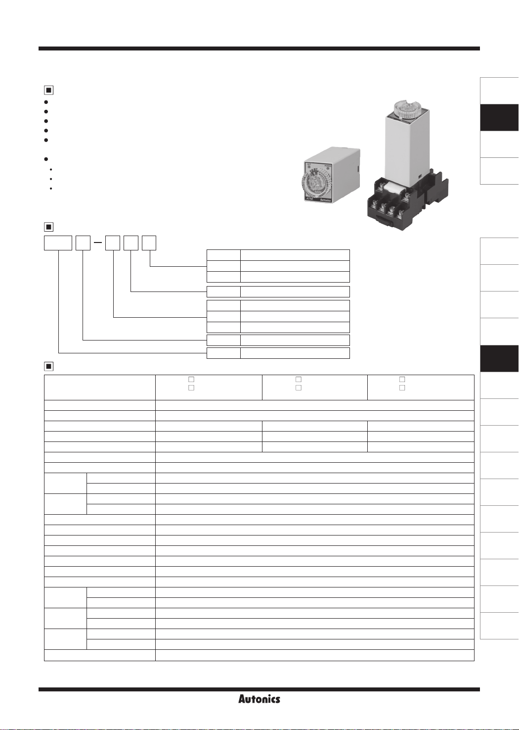
W21.5×H28mm Miniature Timer
Features
Miniature Size (W21.5×H28×L59.3mm)
•
4c (4PDT) contact (250VAC, 3A)
•
High precise time control
•
Easy time setting using dial
•
Various time ranges
•
: 0.1 sec to 3 hour (11 time ranges, dierent by models)
Power supply
•
ATM4-2: 24VDC
ATM4-5: 220VAC 50/60Hz
ATM4-6: 110VAC 50/60Hz
ATM Series
SENSORS
CONTROLLERS
MOTION DEVICES
SOFTWARE
Ordering Information
ATM 4 105 S
Time unit
Time range
Power supply
Output
Item
Specifications
~
ATM4 - 2
Model
Function Power ON Delay
Control time setting range
※
1
0.1 sec to 3 hour
Power supply 24VDCᜡ 220VACᜠ 50/60Hz 110VACᜠ 50/60Hz
Allowable voltage range 21.6-26.4VDCᜡ 200-230VACᜠ 50/60Hz 100-120VACᜠ 50/60Hz
Power consump ion Approx. 1.2W Approx. 3VA Approx. 3VA
Return time Max. 100ms
Timing operation Power ON Start
Control
output
Relay
life cycle
Contact type 4PDT (4c)
Contact capacity 250VACᜠ 3A, 24VDCᜡ 3A resistive load
Mechanical Min. 10,000,000 operations
Electrical Min. 200,000 operations
Repeat error Max. ±0.5% ±10ms
SET error Max. ±10% ±50ms
Voltage error Max. ±0.5% ±10ms
Temperature error Max. ±2% ±10ms
Insulation resistance Over 100MΩ (at 500VDC megger)
Dielectric strength 3,000VAC 50/60Hz for 1 min
Noise immunity ±2kV the square wave noise (pulse width: 1㎲) by noise simulator
Vibra ion
Shock
Environment
Weight
※
1: Refer to time specifications for control time setting range by model.
※
2: The weight includes packaging. The weight in parenthesis is for unit only.
※
Environment resistance is rated at no freezing or condensa ion.
Mechanical 0.75mm amplitude at frequency of 10 to 55Hz (for 1 min) in each X, Y, Z direction for 1 hour
Electrical 0.5mm amplitude at frequency of 10 to 55Hz (for 1 min) in each X, Y, Z direction for 10 min
Mechanical 300m/s² (approx. 30G) in each X, Y, Z direction 3 times
Electrical 100m/s² (approx. 10G) in each X, Y, Z direction 3 times
Ambient temperature -10 to 50℃, storage: -25 to 65℃
Ambient humidity 35 to 85%RH, storage: 35 to 85%RH
※
2
Approx. 48g (approx. 42g)
S Sec (1, 5, 10, 30, 60)
M Min (3, 5, 10, 30, 60)
H Hour (3)
Number Max. time range
2 24VDC
5 220VAC 50/60Hz
6 110VAC 50/60Hz
4 4c (4PDT)
ATM Miniature Analog Timer
S
□
2
M
□
23H
ATM4 -
l
5
5
53H
S
M
Mounting My socket
(sold separately)
ATM4 - 6
l
□ □
6
□ □
63H
S
M
Autonics
N-45
(J)
Temperature
Controllers
(K)
SSRs
(L)
Power
Controllers
(M)
Counters
(N)
Timers
(O)
Digital
Panel Meters
(P)
Indicators
(Q)
Converters
(R)
Digital
Display Units
(S)
Sensor
Controllers
(T)
Switching
Mode Power
Supplies
(U)
Recorders
(V)
HMIs
(W)
Panel PC
(X)
Field Network
Devices
Page 2
ATM Series
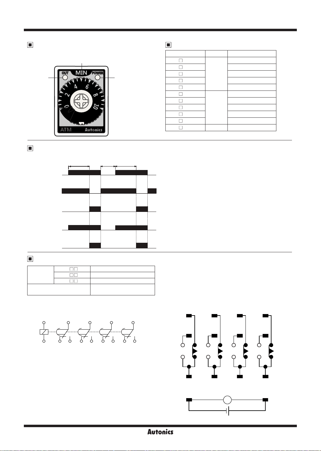
Unit Descriptions Time Specifications
Time unit
(SEC, MIN, HOUR)
Output
indicator
(red)
Operation Specifications
t : setting time, Rt : return time
Power
(13-14)
Time limit N.C.
(9-1, 10-2,
11-3, 12-4)
Time limit N.O.
(9-5, 10-6,
11-7, 12-8)
t tRt
Power
indicator
(green)
-
Model Time unit Time setting range
1S
ATM4-
□
5S 0.5 to 5 sec
ATM4-
□
10S 1 to 10 sec
ATM4-
□
30S 3 to 30 sec
ATM4-
□
60S 6 to 60 sec
ATM4-
□
3M
ATM4-
□
5M 0.5 to 5 min
ATM4-
□
10M 1 to 10 min
ATM4-
□
30M 3 to 30 min
ATM4-
□
60M 6 to 60 min
ATM4-
□
3H HOUR 0.3 to 3 hour
ATM4-
□
SEC
MIN
0.1 to 1 sec
0.3 to 3 min
Power indicator
(green)
Output indicator
(red)
Connections
ATM4-2
□□
SOURCE
CONTACT
● IEC marking ● NEMA marking
~
14
+
ATM4-5
□□
ATM4-6
□□
9 10 11 12
.t----~-----~-----~-----~
T
7-6 7-6
1 2 3 45
~
13
-
※
IEC marking is on the unit.
24VDC 1.2W
200-230VAC 50/60Hz 3VA
100-120VAC 50/60Hz 3VA
250VAC 3A, 24VDC 3A
RESISTIVE LOAD
?i
6 7 8
'?'6
1 2 3 4
5
9 10 11 12
13
T T
6 7 8
14
~
- +
SOURCE
N-46
Autonics
Page 3
Miniature Analog Timer
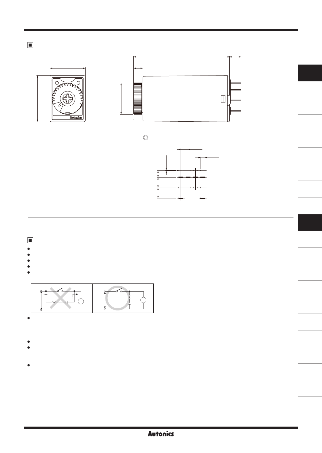
Dimensions
21.5
28
※
Use My socket which is commercially available.
Ø19
5.7
Pin arrangement
4-0.5
4.16.36.4
58 7
[I]
3-4.4
4-2.6
(unit: mm)
SENSORS
CONTROLLERS
MOTION DEVICES
SOFTWARE
(J)
Temperature
Controllers
(K)
SSRs
(L)
Power
Controllers
(M)
Counters
(N)
Timers
Proper Usage
~
Follow instructions in 'Proper Usage'. Otherwise, it may cause unexpected accidents.
•
24VDC power supply should be insulated and limited voltage/current or Class 2, SELV power supply device.
•
When supplying or turning o the power, use a switch or etc. to avoid chattering.
•
Install a power switch or circuit breaker in the easily accessible place for supplying or disconnecting the power.
•
In order to avoid leakage current owing, connect resistance and condenser as (Figure 2).
If connect as (Figure 1), it may cause malfunction due to leakage current.
(Figure 1) (Figure 2)
Power
·1-F-~----~------J
Keep away from high voltage lines or power lines to prevent inductive noise.
•
In case installing power line and input signal line closely, use line lter or varistor at power line and shielded wire at input
signal line.
Do not use near the equipment which generates strong magnetic force or high frequency noise.
Change setting time, time range, operation mode or etc. after turning o the power of the timer.
•
Do not use the unit in the place where ammable/explosive/corrosive gas, humidity, direct sunlight, radiant heat, vibration,
•
impact, or salinity may be present.
Failure to follow this instruction may result in re or explosion.
This unit may be used in the following environments.
•
①
②
③
④
Leakage
current
R C
Indoors (in the environment condition rated in 'Specications')
Altitude max. 2,000m
Pollution degree 2
Installation category II
Power
Timer
►
~I
T
~cnT7
R
C
T
Timer
I
(O)
Digital
Panel Meters
(P)
Indicators
(Q)
Converters
(R)
Digital
Display Units
(S)
Sensor
Controllers
(T)
Switching
Mode Power
Supplies
(U)
Recorders
(V)
HMIs
(W)
Panel PC
(X)
Field Network
Devices
Autonics
N-47
 Loading...