

Autonics CT Series Catalog Page
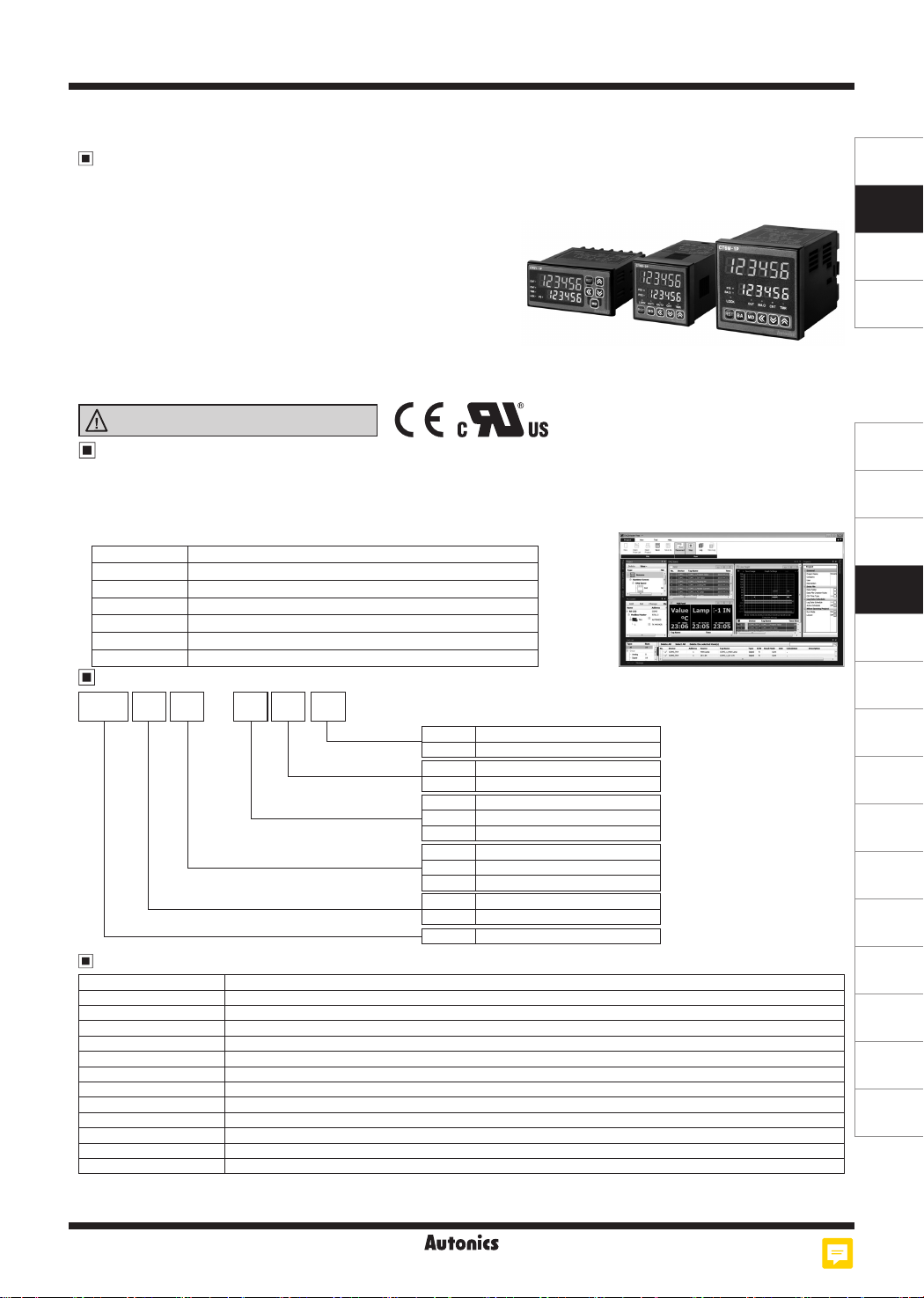
CT Series
DIN W48×H48mm, W72×H36mm, W72×H72mm Counter/Timer
Features
Communication function supported (communication model): RS485 (Modbus RTU)
●
One-shot output time setting range - 0.01 sec to 99.99 sec by setting per 10ms
●
[Counter]
●
Prescale value setting range – 6-digit model: 0.00001 to 99999.9 /
4-digit model: 0.001 to 999.9
9 input modes/11 output modes
BATCH counter,
Count Start Point (counting initial value) setting function
[Timer]
●
13 output modes
Various time setting range – 6-digit model: 0.001 sec to 99999.9 hour / 4-digit model: 0.001 sec to 9999 hour
‘0’ time setting function
Selectable timer memory retention function for indicator model.
Please read “Safety Considerations”
in the instruction manual before using.
DAQMaster (Comprehensive Device Management Program)
● DAQMaster is comprehensive device management program for conve-
nient management of parameters and multiple device data monitoring.
● Visit our website (www.autonics.com) to download user manual and com-
prehensive device management program.
Item Minimum requirements
System IBM PC compatible computer with Intel Pentium Ⅲ or above
Operations Microsoft Windows 98/NT/XP/Vista/7/8/10
Memory 256MB+
Hard disk 1GB+ of available hard disk space
VGA Resolution: 1024×768 or higher
Others RS-232 serial port (9-pin), USB port
Ordering Information
Size
-
Communication
Power supply
Output
No-mark
출출 출출출 출
T
2
4
1P
2P
※
1
I
S
Y
M
4
6
CT
None
RS 485 communication output
24VAC 50/60Hz, 24-48VDC
100-240VAC 50/60Hz
1-stage preset
2-stage preset
Indicator
DIN W48×H48
DIN W72×H36
DIN W72×H72
mm
mm
mm
9999 (4-digit)
999999 (6-digit)
Counter/Timer
CT 2P6 M 4 T
Display digits
Item
Communication Specification
Comm. protocol Modbus RTU with 16-bit CRC
Connection type RS485
Application standard Compliance with EIA RS485
Max. connection 31 units (address: 1 to 127)
Synchronous method Asynchronous
Comm. type Two-wire half duplex
Comm. distance Max. 800m
Comm. speed 2400, 4800, 9600 (factory default), 19200, 38400bps
Comm. response time 5 to 99ms (factory default: 20ms)
Start bit 1-bit (xed)
Data bit 8-bit (xed)
Parity bit None (factory default), Even, Odd
Stop bit 1, 2-bit (factory default: 2-bit)
※
It is recommended to use Autonics communication converter; SCM-WF48 (Wi-Fi to RS485·USB wireless communication converter, sold
separately), SCM-US48I (USB to RS485 converter, sold separately), SCM-38I (RS232C to RS485 converter, sold separately), SCM-US
(USB to Serial converter, sold separately). Please use twisted pair wire for RS485 communication.
< DAQMaster screen >
※
1: CT4S model does not
support indicator type.
M-13
SENSORS
CONTROLLERS
MOTION DEVICES
SOFTWARE
(J)
Temperature
Controllers
(K)
SSRs
(L)
Power
Controllers
(M)
Counters
(N)
Timers
(O)
Digital
Panel Meters
(P)
Indicators
(Q)
Converters
(R)
Digital
Display Units
(S)
Sensor
Controllers
(T)
Switching
Mode Power
Supplies
(U)
Recorders
(V)
HMIs
(W)
Panel PC
(X)
Field Network
Devices
CT Series
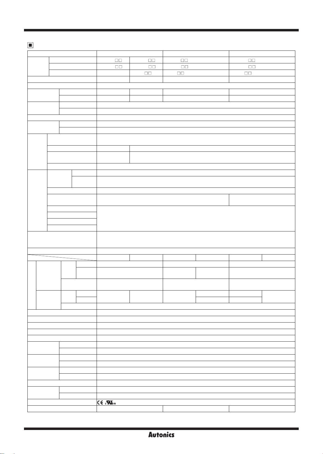
Specications
Series CTS CTY CTM
1-stage preset
Model
Display digits 4-digit 6-digit 6-digit 6-digit
Display method 7 segment (counting value: red, setting value: yellow-green) LED method
Character
size(W×H)
Power supply
Permissible voltage range 90 to 110% of rated voltage
Power
consumption
Counter
Timer
Input method
One-shot output time 0.01s to 99.99s setting
Exter nal power supply Max. 12VDCᜡ ±10%, 10 0mA
Memory retention Approx. 10 years (non-volatile memory)
Insulation resistance Over 100MΩ (at 500VDC megger)
Dielectric strength 2,000VAC 50/60Hz for 1 min
Noise immunity Square -wave noise by noise simulator (pulse width 1㎲) ±2kV
Vibration
Shock
Relay life cycle
Protection structure IP65 (front par t, IEC standard)
Environmental
Approval
Weight
※
※
2-stage preset
Indicator
Counting value 6.5×10mm 4.5×10 mm 4.2×9.5mm 6.6×13mm
Setting value 4.5×8mm 3. 5×7mm 3.5 ×7mm 5×9mm
AC voltage 100 -24 0VACᜠ 50/60Hz
AC/DC voltage 24VACᜠ 50/60Hz, 24-48VDC
AC voltage M ax . 12VA
AC/DC voltage AC: Max. 10VA, DC: Max. 8W
INA/INB
Max. counting speed
Counting range -999 to 9999 -99999 to 999999
Scale
Min. input signal width RES ET: Selectable 1ms/20ms
Time range
Operation method Count up, Count down, Count Up/Down
Min. input signal width INA, INH, RESET: Selectable 1ms/20ms
Repeat error
Set error
Voltage error
Temp. error
Contact
output
Solid state
Control output
output
(NPN open
collector)
※
1
1: The weight includes packaging. The weight in parenthesis is for unit only.
Environment resistance is rated at no freezing or condensation.
4-digit 9.999s, 99.99s, 999.9s, 9999s, 99m 59s, 999.9m, 9999m, 99h 59m, 9999h
6-digit
1-stage SPDT(1c): 1 S PDT(1c): 1 S PDT(1c): 1
Typ e
2-stage SPST(1a): 2
Capacity
1-stage
Typ e
2-stage
Capacity Max. 30VDCᜡ, 100mA
Mechanical 0.75mm amplitude at frequency 10 to 55Hz (for 1 min) in each X, Y, Z direction for 1 hour
Malfunction 0.5mm amplitude at frequency 10 to 55Hz (for 1 min) in each X, Y, Z direction for 10 min
Mechanical 3 00m/s² (approx. 30G) in each X, Y, Z direction for 3 times
Malfunction 100m/s² (approx. 10G) in each X, Y, Z direction for 3 times
Mechanical Min. 10,000,000 operations
Malfunction Min. 100,000 operations
Ambient temp. -10 to 55℃, storage: -25 to 65
Ambient humi. 35 to 85%RH, storage: 35 to 85%RH
CT4 S -1P CT6 S-1P CT 6Y-1P CT6M-1P
CT4 S -2P CT6S-2P CT6 Y-2 P CT6M-2P
-
Selectable 1cps / 30cps / 1kcps / 5kcps / 10kcps
Decimal point
up to third digit
999.999s, 9999.99s, 99999.9s, 999999s, 99m 59.99s, 999m 59.9s, 9999m 59s, 99999.9m, 999999m,
99h 59m 59s, 9999h 59m, 99999.9h
In case of power ON start: Max. ±0.01% ±0.05s
In case of signal start: Max. ±0.01% ±0.03s
Selectable voltage input or no-voltage input
[Voltage input]-input impedance: 5.4kΩ, [H]: 5-30VDCᜡ, [L]: 0-2VDC
[No-voltage input]-short-circuit impedance: Max. 1kΩ, shor t-circuit residual voltage: Max. 2VDC
Standard Comm. Standard Comm. Standard Comm.
250 VACᜠ 5A, 30VDCᜡ 5A
resistive load
1
Approx. 212g (approx. 159g) Approx. 228g (approx. 140g) Approx. 322g (approx. 252g)
CT6S-I CT6Y- I CT6M-I
ᜡ
Decimal point up to fifth digit
SPST(1a): 1,
SPDT(1c) : 1
250 VACᜠ 3A, 30VDCᜡ 3A
resistive load
-
1
℃
SP ST(1a): 2 SPST(1a): 1, SPDT(1c): 1
1 2
-
INA, RESET, INHIBIT, BATCH
RESET: Selectable 1ms/20ms
ᜡ
250 VACᜠ 5A, 30VDCᜡ 5A
resistive load
3
2
M-14
Programmable Counter/Timer
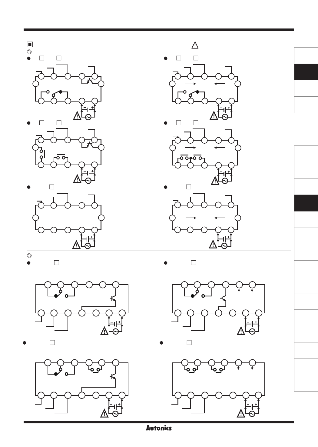
Connections
CTS Series
CT
12VDC 100mA
INB/INH
INA
S-1P
※
2
6172839410
OUT
COM
NO
250VAC 5A, 30VDC 5A
RESISTIVE LOAD
S-2P
※
2
617
CT
12VDC 100mA
INB/INH
INA
2
OUT1 OUT2
250VAC 5A, 30VDC 5A
RESISTIVE LOAD
CT6S-I
12VDC 100mA
INB/INH
INA
※
2
6172839410
CTY Series
CT6Y-1P
INA
INB/INH
12VDC 100mA
CT6Y-2P
INA
INB/INH
12VDC 100mA
250VAC 3A, 30VDC 3A
RESISTIVE LOAD
NC COM NO
819210311412513
OUT
※
2
250VAC 3A, 30VDC 3A
RESISTIVE LOAD
NC COM
819210311412513
OUT2
※
2
RESET
0VDC
NC
RESET
0VDC
839410
RESET
0VDC
RESET0VDC
NO
RESET0VDC
5
5
5
OUT
OUT1
1211
※
1
1211
※
1
1211
※
1
OUT
30VDC
100mA
OUT2
30VDC
100mA
SOLID
STATE OUT
30VDC
100mA
OUT
6 7
SOLID
STATE OUT
30VDC
100mA
OUT2
6 7
Be sure that connection is varied by
supporting RS485 communication.
S-1P
※
2
T
RESET
0VDC
CT
12VDC 100mA
INB/INH
INA
6172839410
OUT
RS485
1211
A(+) B(-)
5
COM
OUT2
NC
T
RS485
RESET
0VDC
B(-)
※
1
1211
5
※
1
NO
250VAC 5A, 30VDC 5A
RESISTIVE LOAD
CT
S-2P
12VDC 100mA
※
2
INB/INH
INA
6172839410
A(+)
OUT1
250VAC 5A, 30VDC 5A
RESISTIVE LOAD
CT6S-I T
12VDC 100mA
※
2
INB/INH
INA
6172839410
A(+) B(-)
CT6Y-1P
250VAC 3A, 30VDC 3A
RESISTIVE LOAD
NC COM NO
819210311412513
INA
※
2
※
1
INB/INH
12VDC 100mA
CT6Y-2P
250VAC 3A, 30VDC 3A
RESISTIVE LOAD
819210311412513
OUT2 OUT1
T
T
OUT
RS485
RESET
0VDC
5
SOLID
STATE OUT
30VDC
100mA
OUT
RESET0VDC
1211
※
1
A(+) B(-)
RS485
A(+)
RS485
6 7
B(-)
※
1
SENSORS
CONTROLLERS
MOTION DEVICES
SOFTWARE
(J)
Temperature
Controllers
(K)
SSRs
(L)
Power
Controllers
(M)
Counters
(N)
Timers
(O)
Digital
Panel Meters
(P)
Indicators
(Q)
Converters
(R)
Digital
Display Units
(S)
Sensor
Controllers
(T)
Switching
Mode Power
Supplies
(U)
Recorders
(V)
HMIs
(W)
Panel PC
(X)
Field Network
Devices
6 7
INA
※
2
※
1
INB/INH
12VDC 100mA
RESET0VDC
※
1
M-15
CT Series
CT6Y-I
1 2 3
INA
※
2
INB/INH
12VDC 100mA
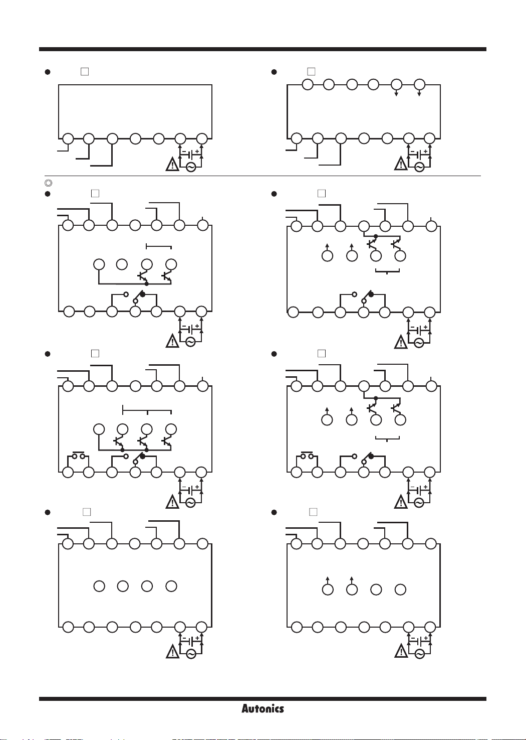
CTM Series
CT6M-1P
12VDC 100mA
INB
INA
819210311
CT6M-2P
12VDC 100mA
INB
INA
8
OUTPUT
COMMON
OUT1
192103
250VAC 5A, 30VDC 5A
RESISTIVE LOAD
CT6M-I
12VDC 100mA
INB
INA
8
INHIBIT
RESET
SOLID STATE OUT
OUTPUT
COMMON
15
16
250VAC 5A, 30VDC 5A
RESISTIVE LOAD
INHIBIT
SOLID STATE OUT
OUT1 OUT2 BATCH
15
16
OUT2
INHIBIT
4 5 6 7
RESET0VDC
2
※
0VDC
12
30VDC
100mA
OUT BATCH
18
OUT
4
5
NCCOMNO
2
※
RESET
0VDC
11
12
30VDC
100mA
18
4
5
NCCOMCOM NONO
2
※
RESET
0VDC
11
12
BATCH
RESET
131714
6 7
BATCH
RESET
131714
6 7
131714
CT6Y-I T
A(+) B(-)
819210311412513
RS485
6 7
INA
※
2
INB/INH
12VDC 100mA
CT6M-1P T
12VDC 100mA
INB
INA
INHIBIT
※
1
819210311
RS485
15
16
A(+) B(-)
250VAC 5A, 30VDC 5A
※
1
RESISTIVE LOAD
CT6M-2P T
12VDC 100mA
INB
INA
819210311
OUT1
250VAC 5A, 30VDC 5A
※
1
RESISTIVE LOAD
INHIBIT
RS485
15
16
A(+) B(-)
OUT2
CT6M-I T
12VDC 100mA
INB
INA
8
INHIBIT
RESET0VDC
2
※
RESET
0VDC
12
OUT BATCH
SOLID STATE OUT
OUT
4
5
NCCOMNO
2
※
RESET
0VDC
12
OUT2 BATCH
SOLID STATE OUT
4
5
NCCOM COMNO NO
2
※
RESET
0VDC
11
12
131714
18
30VDC
100mA
6 7
131714
18
30VDC
100mA
6 7
131714
※
BATCH
RESET
※
BATCH
RESET
※
1
1
1
15
16
192103
※
1: AC Voltage: 100-240VAC 50/60Hz
4
18
5
6 7
※
1
192103
AC/DC Voltage: 24VAC 50/60Hz, 24-48VDC
※
2: Counter operation: If INHIBIT signal is applied, count input will be prohibited.
Timer operation: If INHIBIT signal is applied, time progressing will stop. (HOLD)
M-16
RS485
15
16
A(+) B(-)
18
4
5
6 7
※
1
Programmable Counter/Timer
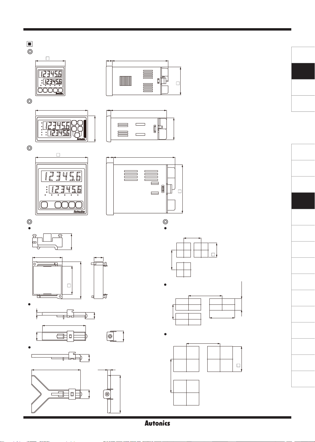
Dimensions
CTS Series
48
CTY Series
72
6 77
36
CTM Series
72
10 85
Bracket Panel cut-out
CTS Series CTS Series
26.3
48.3 15
9010
45
30.2
67
Min. 55
Min. 62
+0.6
(unit: mm)
SENSORS
CONTROLLERS
MOTION DEVICES
SOFTWARE
(J)
Temperature
Controllers
(K)
SSRs
(L)
Power
Controllers
(M)
Counters
(N)
Timers
(O)
Digital
Panel Meters
0
45
(P)
Indicators
(Q)
Converters
CTY Series
4
12
CTM Series
(R)
45.8
60.2
CTY Series
Min. 91
+0.7
9
Min. 40
68
0
+0.5
31.5
0
60
14.5
10
68
4.4
CTM Series
Min. 91
+0.7
0
68
Min. 91
12
52
Digital
Display Units
(S)
Sensor
Controllers
(T)
Switching
Mode Power
Supplies
(U)
Recorders
(V)
HMIs
(W)
Panel PC
(X)
Field Network
Devices
M-17
CT Series
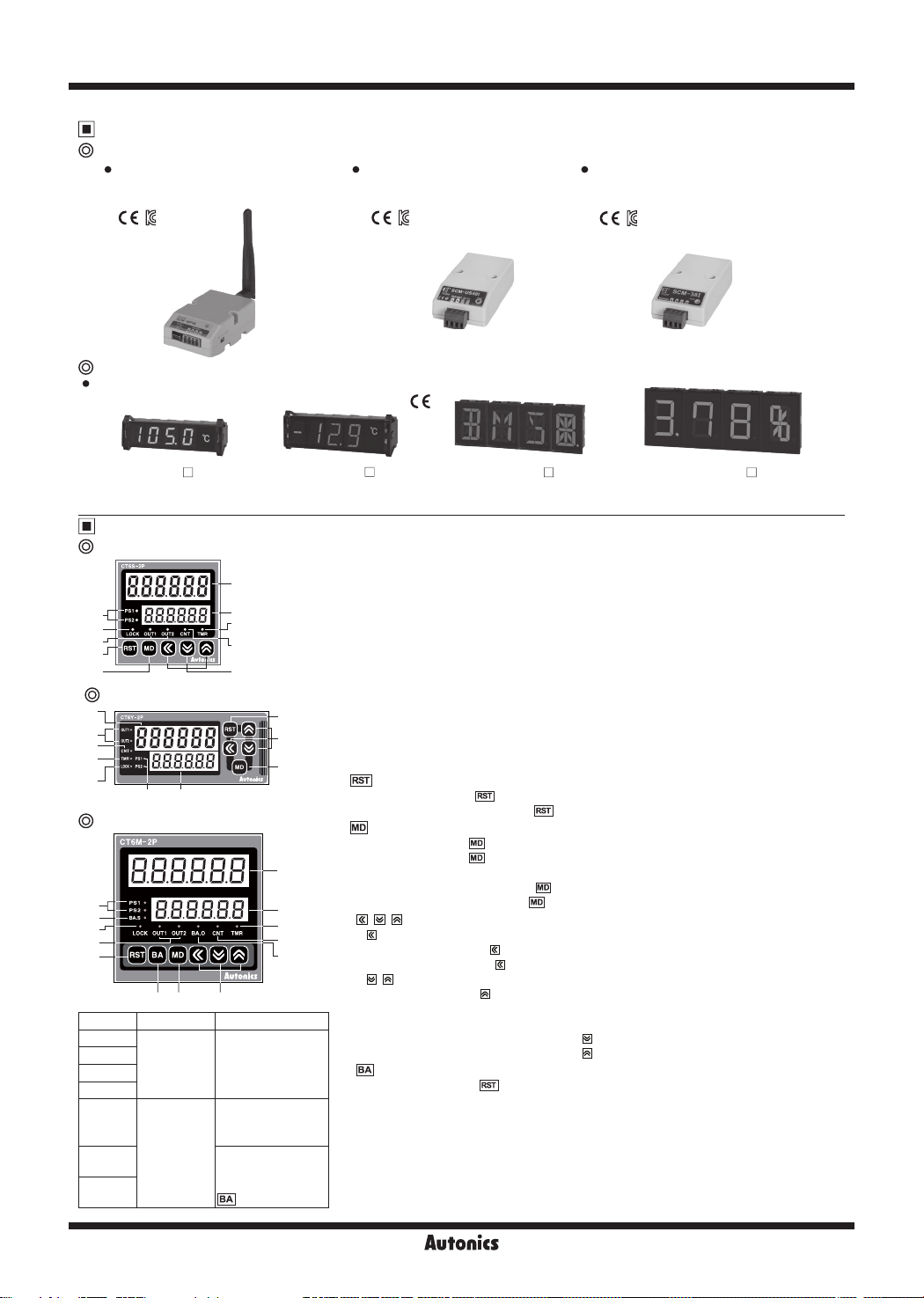
Sold Separately
Communication converter
SCM-WF48
( Wi-Fi to RS485·USB wireless
communication converter)
Display Units (DS/DA-T Series)
DS/DA-T Series
(RS485 communication input type display unit)
SCM-US48I
(USB to RS485 converter)
SCM-38I
(RS232C to RS485 converter)
※
Connect RS485 communication input type display unit (DS/DA-T Series) and RS485 communication output model of CT Series,
the display unit displays present value of the device without PC/PLC.
DS16- T
DS22/DA22- T
DS40/DA40- T DS60/DA60- T
Unit Description
CTS Series
1
6
3
7
8
9
2
5
4
10
CTY Series
1
7
4
5
3
6 2
CTM Series
6
13
3
7
8
1011
9
Model Changed Notice
CT4S-1P
CT6S-1P
CT6Y-1P
CT6M-1P
CT6S-I
CT6Y-I
CT6M-I
PS2→PS
OUT2→OUT
PS2→PS
There are no
PS1, OUT1 LEDs.
There are no
PS1, OUT1, OUT2
LEDS.
There are no
PS1, OUT1, OUT2,
BA.S, BA.O LEDs,
key.
8
10
9
12
1. Counting value display component (red)
RUN mode: Displays counting value for counter operation or time progress value for timer
operation.
Function setting mode: Displays setting item.
2. Setting value display component (yellow-green)
RUN mode: Displays setting value.
Function setting mode: Displays setting content.
3. Key lock indicator (LOCK):
4. Counter indicator (CNT):
5. Timer indicator (TMR):
operation.
6. Preset value checking and changing indicator (PS1, PS2)
:
Turns ON when checking and changing preset value.
7. Output indicator (OUT1, OUT2):
8. key
RUN mode: Press the key to reset the counting value.
BATCH counter mode: Press the key to reset the batch counting value.
9. key
RUN mode: Hold the key over 3 sec to enter function setting mode(parameter setting).
1
2
5
4
Function setting mode: Press the key to select function setting mode parameter.
10.
1) key
2) , key
11. key
RUN mode: Press the key to enter BATCH counter indication mode.
12. BATCH output indicator (BA.O) (red)
13. BATCH preset value checking and changing indicator (BA.S) (yellow-green)
:
※
The indicator type does not exist in CT4S model.
Hold the key over 5 sec to enter function setting mode(communication
setting).
key
, ,
RUN mode: Press the key to enter preset mode.
Preset mode: Press the key to move preset digits.
RUN mode: Hold the key over 1 sec to enter Function setting check mode.
Preset mode: Used for increasing or decreasing preset value.
Function setting mode: Changes the settings.
Function setting check mode: Press the key to move the previous parameter.
Turns ON when checking and changing BATCH preset value.
Turns ON for key lock setting.
Turns ON for counter operation.
Flashes (progressing time) or Turns ON (stopping time) for timer
Turns ON for the dedicated control output ON.
Hold the key over 3 sec to return RUN mode.
Press the key to the next parameter.
M-18
Programmable Counter/Timer
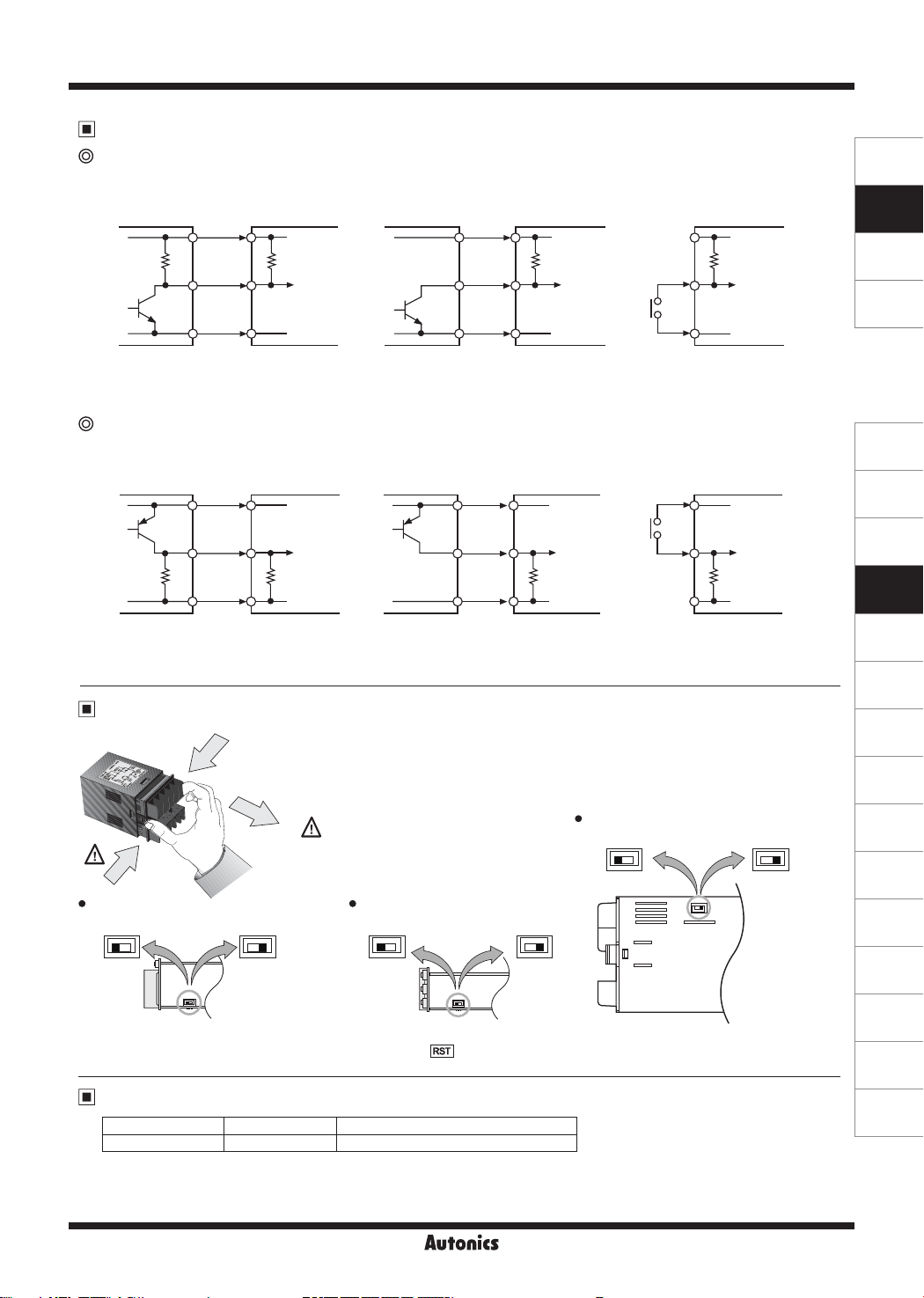
Input Connections
No-voltage input (NPN)
● Solid-state input (standard sensor: NPN output type sensor) ● Contact input
Counter/Timer
※
1
CT Series
+12V
5.4Ω
Inner circuit
of input part
0V
Sensor
Sensor
Brown Brown
Black Black
Blue Blue
(NPN output) (NPN open collector output)
※
1: INA, INB/INH, RESET, INHIBIT, BATCH RESET input part
※
2: Counting speed: 1 or 30cps setting (counter)
Voltage input (PNP)
● Solid-state input (standard sensor: PNP output type sensor) ● Contact input
Counter/Timer
※
CT Series
Sensor
+12V
1
Inner circuit
of input part
5.4
㏀
0V 0V 0V
(PNP open collector output)
Sensor
Brown Brown
Black Black
Blue Blue
(PNP output)
※
1: INA, INB/INH, RESET, INHIBIT, BATCH RESET input part
※
2: Counting speed: 1 or 30cps setting (counter)
Input Logic Selection [No-Voltage Input (NPN)/Voltage Input (PNP)]
CTS Series
①
①
CTS CTY
No-voltage input (NPN) Voltage input (PNP)
NPN NPNPNP PNP
SW1
How to change settings
※
Power OFF → change settings → power ON → press key or input signal (min. 20ms)
1. The power must be cut o.
2. Squeeze toward ① and pull toward ② as the gure. (CTS/CTY Series)
3. Select input logic by using input logic switch (SW1) inside Counter/Timer.
4. Push a case in the opposite direction of ②.
②
5. Then supply the power to counter/timer.
Turn OFF the power before
changing input logic (PNP/NPN)
No-voltage input (NPN) Voltage input (PNP)
NPN NPNPNP PNP
SW1
Counter/Timer
CT Series
+12V +12V
5.4Ω 5.4Ω
※
1
Inner circuit
of input part
0V 0V
Counter/Timer
CT Series
+12V +12V
1
※
Inner circuit
of input part
5.4
㏀
CTM
Voltage input (PNP) No-Voltage input (NPN)
PNP PNPNPN NPN
2
※
2
※
SW1
Counter/Timer
CT Series
Counter/Timer
CT Series
5.4Ω
Inner circuit
of input part
Inner circuit
of input part
SENSORS
CONTROLLERS
MOTION DEVICES
SOFTWARE
(J)
Temperature
Controllers
(K)
SSRs
(L)
Power
Controllers
(M)
Counters
(N)
Timers
(O)
Digital
Panel Meters
(P)
Indicators
(Q)
Converters
(R)
Digital
Display Units
(S)
Sensor
Controllers
(T)
Switching
Mode Power
Supplies
(U)
Recorders
(V)
HMIs
(W)
Panel PC
Error Display and Output Operation
Error Display Error description Troubleshooting
※
When error occurs, the output turns OFF.
※
When 1st setting value is set as 0 (zero), OUT1 maintains OFF.
When 2nd setting value is smaller than 1st setting value, 1st setting value is ignored and only OUT2 output operates.
※
Indicator model does not have error display function.
ERR0
Setting value is 0. Change the setting value anything but 0.
M-19
(X)
Field Network
Devices
CT Series
Output Connections
Contact output Solid-state output
Counter/Timer
CT Series
Counter/Timer
CT Series
1
※
(Power of load)
Load
※
Use proper load not to exceed the capacity.
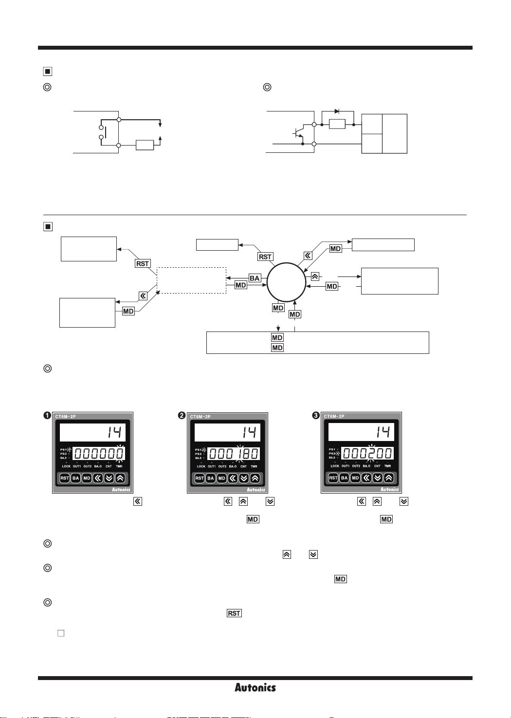
Operations and Functions
BATCH RESET
BATCH counter
※
1
Change of
BATCH setting
value.
※
1. If no key is touched for 60 sec,
the counter will return to RUN mode
without being restored.
indication mode
※
BATCH counter is available
for CT6M-1P/2P model
only.
Load
※
Use proper load and power for load not to excess ON/OFF
capacity (Max. 30VDC, 100mA) of solid state output.
※
Be sure not to apply reverse polarity of power.
※
1: When using inductive load (relay etc.), surge absorber
(diode, varistor etc.) must be connected between both
sides of the load.
RESET
RUN
mode
3sec
5sec
3sec
Function 3sec: Enters into parameter 1 group
setting mode 5sec: Enters into parameter 2 group
1sec
(+)
(-)
※
1
Preset mode
Function setting
1sec
Power
for load
(DC)
check mode
Change of preset (counter/timer)
● Even if changing the preset value, input operation and output control will continue. In addition, the preset value could
be set to 0 and the output of 0 preset value turns ON. According to output mode, preset value could not be set to 0.
(When setting to 0, preset value "0" will flash 3 times.)
In RUN mode, press the key
to enter preset mode.
'PS1' indicator turns ON and
rst digit of preset value ashes.
Function setting check mode
Press the , and keys to
set the desired value (example,
180
). Press the key to
enter the PS2 setting mode.
Press the , and keys to
set the desired value (example,
200
). Press the key to
return RUN mode.
Setting value of function setting mode can be conrmed using the and keys.
Switching display function in preset indicator
Setting value1 (PS1) and setting value2 (PS2) are displayed each time pressing key in PRESET2 model.
(in timer, it is available for
OND, ONd1
or
output mode.)
ONd2
Reset
In RUN mode or function setting mode, if pressing key or applying the signal to the RESET terminal on the back
side, present value will be reset and output will maintain o status.
-CT
S: Short no. 8 and 10 terminals for voltage input (PNP), short no. 9 and 10 terminals for non-voltage input (NPN).
-CT6Y: Short no. 3 and 5 terminals for voltage input (PNP), short no. 4 and 5 terminals for non-voltage input (NPN).
-CT6M:
Short no. 10 and 12 terminals for voltage input (PNP), short no. 11 and 12 terminals for non-voltage input (NPN).
M-20
Programmable Counter/Timer
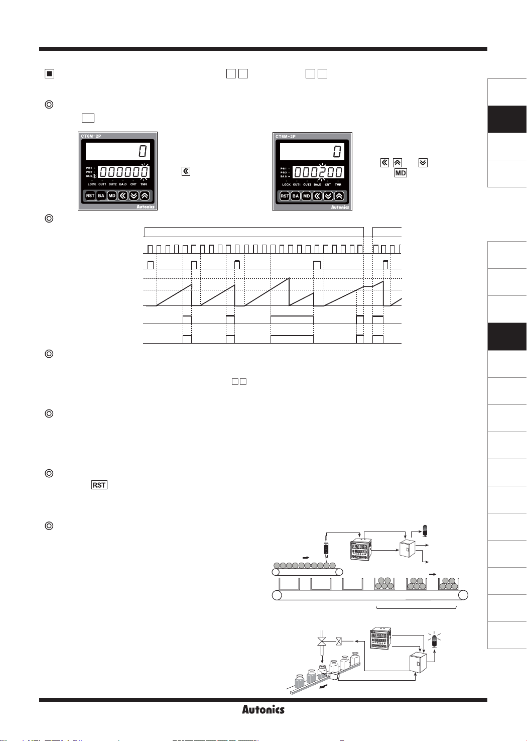
BATCH Counter (for CT6M-1P /CT6M-2P Model Only)
In BATCH counter indication mode, 'BATCH counter value' is displayed in count indicator and 'BATCH counter setting value' is
displayed in preset indicator.
Change of BATCH setting value
If pressing BA key in Run mode, it will enter into BATCH counter indication mode.
1.
It enters into setting
value change mode
using key. (BA.
S lights, first digit
setting value flashes.)
of
2.
BATCH value is set to '200'
using , and keys,
then press key to complete
BATCH setting value and
move to BATCH counter indication mode.
SENSORS
CONTROLLERS
MOTION DEVICES
SOFTWARE
BATCH counter operation
ON
Power
OFF
Preset output
Batch Reset
999999
Batch setting value
0
put
ON
OFF
ON
OFF
BA.O LED
Batch out-
BATCH counting operation
● BATCH counting value is increasing until BATCH reset signal applied. BATCH counting value will be circulated when it is over 999999.
1) BATCH counting operation in Counter: Counts the number of reaching setting value of CT6M-1P or reaching dual setting value
of CT6M-2P
2) BATCH counting operation in Timer: Counts the number of reaching setting time. (In case of "
FLK
" output mode, count the
number of reaching T.off setting time and T.on setting time.)
BATCH output
● If input signal is applied while changing BATCH setting value, counting operation and output control will be performed.
●
If BATCH count value equals to BATCH setting value, BATCH output will be ON and maintain ON status
until BATCH reset
signal is applied.
●
When the power is cut off then resupplied in status of BATCH output is ON, BATCH output maintains ON
status until
BATCH reset signal is applied.
BATCH reset input
● If pressing key or applying the signal to BATCH reset terminal on the back side panel, BATCH counting value will
be reset. When selecting voltage input (PNP), short terminals 10 and 14, or when selecting no-voltage input (NPN), short
terminals 11 and 14 to reset.
● When BATCH reset is applied, BATCH counting value maintains at 0 and BATCH output maintains in the OFF status.
Second
box
Control
BATCH output
lamp
Control signal
for packing
Control signal
for conveyor
First
box
Productivity:
500 bottels
Lamp on when
it is completed.
BATCH counting
nish lamp
box
Application of BATCH counter function
● Counter
In case, put 5 products in a box then pack the boxes when they
reaches to 200.
Counter preset setting value="5", BATCH setting value="200"
-
When the count value of counter reaches to the preset value
-
"5", the control output (OUT) will be on, and at this time the
count value of the BATCH counter will be increased by "1".
The control box which is received the control output (OUT)
repeatedly controls conveyor to move the full box and to
place the next empty box for standby. When the BATCH
count value reaches to "200", BATCH output will be ON.
Then the control box stops conveyor and provides a control
signal for packing.
● Timer
Fills milk into the bottle for 3 sec (setting time) When 500
bottles are filled, BATCH counting finish lamp is turned on.
(Setting time: 3 sec, BATCH setting value: 500)
Solenoid valve
(Open valve
for 3 sec)
Count input BATCH output
Control
output
(OUT)
CT6M-1P4
Bottle sensing
Control box
Preset value = 5
Third
box
Current BATCH count value = 3
BATCH output
Control
CT6M-
1P4
Control the
operation valve
sensor
output
(J)
Temperature
Controllers
(K)
SSRs
(L)
Power
Controllers
(M)
Counters
(N)
Timers
(O)
Digital
Panel Meters
(P)
Indicators
(Q)
Converters
(R)
Digital
Display Units
(S)
Sensor
Controllers
(T)
Switching
Mode Power
Supplies
(U)
Recorders
(V)
HMIs
(W)
Panel PC
(X)
Field Network
Devices
M-21
 Loading...