

Page 1
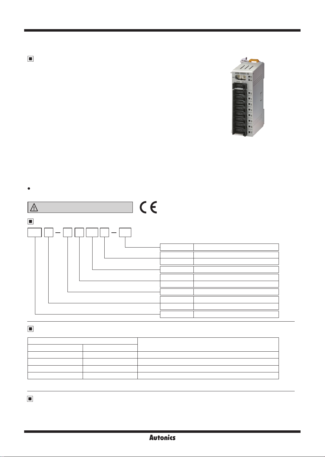
ARM Series
Modbus Sensor Connector Type Digital Remote I/O
Features
● Modbus RTU standard protocol
● Saving work time for wiring with sensor connector
(CNE series, sold separately)
● Compact size
: Small size with W26×L76×H54mm to install at narrow space
: Available DIN Rail mounting and bolt mounting method
● Low-speed (16-bit/30CPS) counter function
● Real-time monitoring by various functions
: Communication speed auto-recognition
: Reading number of expansion units and specifications,
Reading model name of basic and expansion units
: Monitoring Single byte input/output, Multi byte input/output and status Flag
● Easy expansion
: Available to connect up to 63 basic units per 1 master unit
: Available to connect up to 7 expansion units per 1 basic units
(controllable input /output for max. 64 points)
: Combines the desired specifications of input/output by various input/output units
: Organizes power and communication system by only communication cable lines
High reliability
: Built-in surge, short, overheat, reverse power polarity and static prevention circuits
Please read “Safety Considerations”
in the instruction manual before using.
Ordering Information
AR M D 4SI N08
Terminal block
I/O specifications
I/O points
I/O type
Digital/Analog
Network
Item
4S Sensor connector type (4-pin socket)
N NPN open collector
P PNP open collector
08 8 points type
I Input type
O Output type
D Digital type
M Basic unit (Modbus RTU)
X Expansion unit (DeviceNet/Modbus)
AR Autonics Remote I/O
Models
Models
Basic unit Expansion unit
ARM-DI08N-4S ARX-DI08N-4S
ARM-DI08P-4S ARX-DI08P-4S
ARM-DO08N-4S
ARM-DO08P-4S
※Low speed counter of digital output type is available only when using with digital input type.
Manual
For the detail information and instructions of communication setting and Modbus mapping table, please refer to user
manual for communication, and be sure to follow cautions written in the technical descriptions (catalog, website).
Visit our website (www.autonics.com) to download manuals.
※
※
ARX-DO08N-4S
ARX-DO08P-4S
※
※
Specication
10-28VDC NPN input 8-point, low-speed counter (10mA/point)
10-28VDC PNP input 8-point, low-speed counter (10mA/point)
10-28VDC NPN output 8-point, low-speed counter (0.3mA/point)
10-28VDC PNP output 8-point, low-speed counter (0.3mA/point)
X-34
Page 2
Modbus Digital Remote I/O
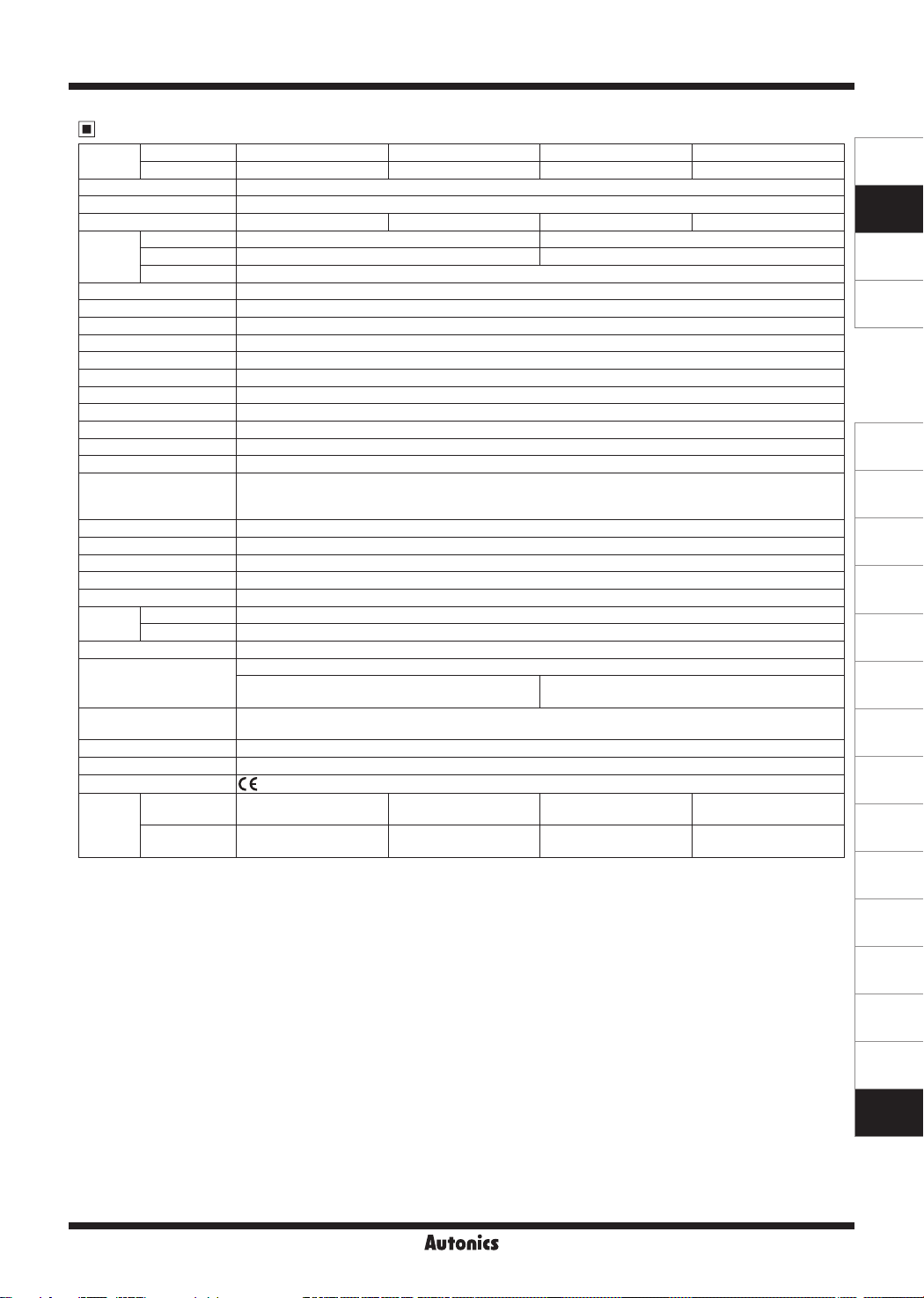
Specifications
Model
Basic unit
Expansion unit
ARM-DI08N-4S
ARX-DI08N-4S ARX-DI08P-4S ARX-DO08N-4S ARX-DO08P-4S
Power supply Rated voltage: 24VDCᜡ, Voltage range: 12-28VDC
Power consumption Max. 3W
I/O points NPN input 8-point PNP input 8-point NPN output 8-point PNP output 8-point
Control
I/O
Special function (input) Counter for 16-bit (30CPS
Communication speed
Voltage 10-28VDCᜡ input 10-28VDCᜡ output (voltage drop: max. 0.5VDCᜡ)
Current 10mA/point (sensor current: 150mA/points) 0.3A/point (leakage current: max. 0.5mA )
Common 8 points, Common
※
2
2400, 4800, 9600, 19200, 38400, 57600, 115200bps (default: 9600bps)
Communication method 2-wire half duplex
Communication distance Max. 800m
Multi-drop Max. 32 multi-drop
Medium access POLL
Application standard Compliance with EIA RS485
Protocol Modbus RTU
Data bit 8-bit
Stop bit 1-bit or 2-bit (default: 2-bit)
Parity bit None/Odd/Even (default: none)
I/O and inner circuit: photocoupler insulation
Isolation method
Modbus to internal bus and inner circuit: insulation
Unit power: non-insulation
Insulation resistance Over 200MΩ (at 500VDC megger)
Noise immunity ±240V the square wave noise (pulse width: 1㎲) by the noise simulator
Dielectric strength 1,000VAC 50/60Hz for 1 min
Vibration 1.5mm amplitude at frequency of 10 to 55Hz (for 1 min) in each X, Y, Z direction for 2 hours
Shock 500m/s2 (approx. 50G) in each X, Y, Z direction for 3 times
Environment
Ambient temp. -10 to 55℃, storage: -25 to 75
Ambient humi. 35 to 85%RH, storage: 35 to 85%RH
Protection structure IP20 (IEC standards)
Surge, short-circuit, overheat (over 165℃) and ESD protection, reversed polarity protection circuit
Protection circuit
Overcurrent protection circuit
(operated at min. 0.17A)
Indicator
Network status (NS) LED (green, red), unit status (MS) LED (green, red)
I/O status LED (input: green, output: red)
Material Front case, body case: Polycarbonate
Mounting DIN rail or bolt mounting type
Approval
Basic
※
3
Weight
Expansion
※
1: CPS (counter per second): Specication of accepting external signals per second
※
2: The communication speed is automatically set to the communication speed of the Master (PC, PLC, etc.).
Approx. 123.3g
(approx. 61.8g)
Approx. 117.5g
(approx. 56g)
When changing the communication speed during operation, the network status (NS) LED ashes in red and communication is not
possible.
※
3: The weight includes packaging. The weight in parenthesis is for unit only.
※
Environment resistance is rated at no freezing or condensation.
ARM-DI08P-4S ARM-DO08N-4S ARM-DO08P-4S
ᜡ
※
1
) (only when using digital input unit of ARM, ARX)
℃
Overcurrent protection circuit
(operated at min. 0.7A)
Approx. 123.3g
(approx. 61.8g)
Approx. 118.5g
(approx. 57g)
Approx. 123.3g
(approx. 61.8g)
Approx. 119.5g
(approx. 58g)
Approx. 123.3g
(approx. 61.8g)
Approx. 120.5g
(approx. 59g)
SENSORS
CONTROLLERS
MOTION DEVICES
SOFTWARE
(J)
Temperature
Controllers
(K)
SSRs
(L)
Power
Controllers
(M)
Counters
(N)
Timers
(O)
Digital
Panel Meters
(P)
Indicators
(Q)
Converters
(R)
Digital
Display Units
(S)
Sensor
Controllers
(T)
Switching
Mode Power
Supplies
(U)
Recorders
X-35
(V)
HMIs
(W)
Panel PC
(X)
Field Network
Devices
Page 3
ARM Series
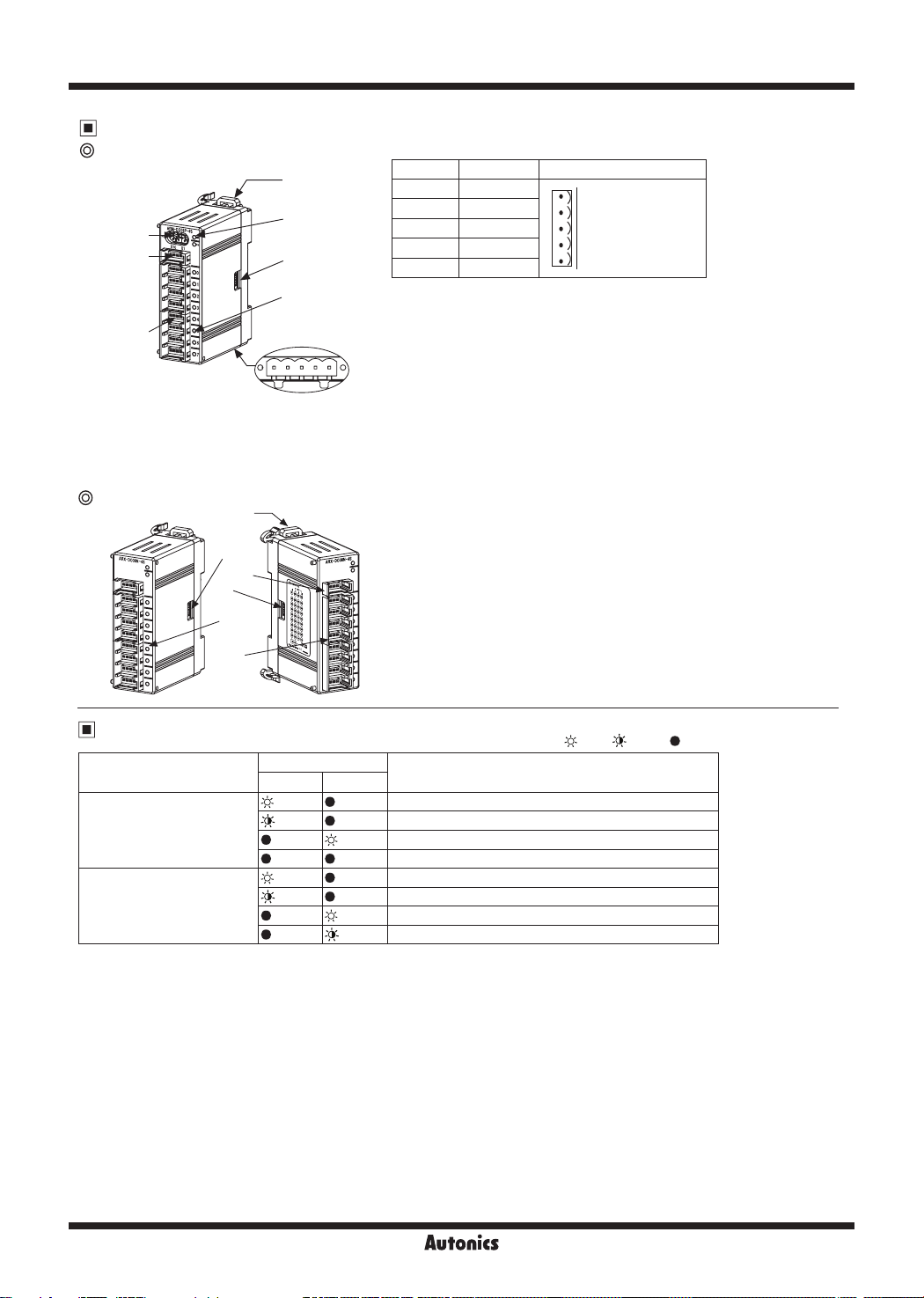
Unit Descriptions
Basic unit
2
8
7
1. Network connector
5
3
6
4
No. For Organization
5 24VDC (+)
4 GND
3 N·C
2 B
1 A
2. Rotary switch for address
5: 24VDC
4: GND
3: N·C
2: B
1: A
: Rotary switch for setting the address
×10 represents tens digit and ×1 represents ones digit.
1
3. Status LED
4. I/O status LED
5. Rail lock
6. Connector output part
7. Sensor connector
: It displays the status of unit (MS) and network (NS).
: It displays each I/O status.
: It is used for mounting DIN rail or with bolts.
: It connects an expansion unit.
: It is used for connecting external device I/O.
8. External power connector
: It is used for supplying external power.
Expansion unit
Status LED
Item
Unit status (MS) LED
Network status (NS) LED
3
4
6
1
2
5
LED status
Red Green
1. Connector input part
: It connects expansion unit and is joined into
the expansion connector output.
2. I/O status LED
3. Rail lock
4. Connector output part
5. Sensor connector
6. External power connector
Description
Error of expansion units
Error of MAC ID
Normal operation
Power is not supplied
Not supported communication speed (at auto baud rate)
Error of packet
Normal communication
Communication standby
: It displays each I/O status.
: It is used for mounting DIN rail or with bolts.
: It connects an expansion unit.
: It is used for connecting external device I/O.
: It is used for supplying external power.
( : ON, : Flash,
: OFF )
X-36
Page 4
Modbus Digital Remote I/O
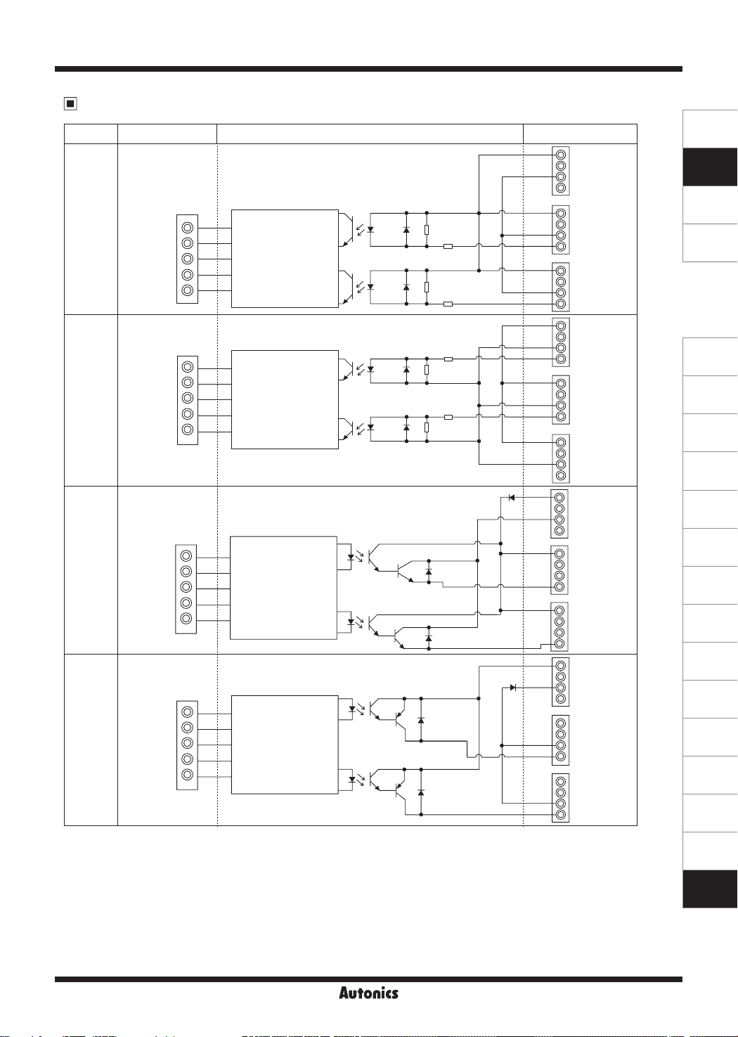
I/O Circuit Diagram
Type Network connector Inner circuit Sensor connector
VDC
NC
GND
NC
VDC
NPN
input
PNP
input
NPN
output
PNP
output
SHIELD
24VDC
GND
SHIELD
24VDC
GND
SHIELD
24VDC
GND
SHIELD
24VDC
GND
A
B
Inner circuit
A
B
Inner circuit
A
B
Inner circuit
A
B
Inner circuit
NC
GND
IN0
VDC
NC
GND
IN1
VDC
NC
GND
IN0
VDC
NC
GND
IN1
VDC
NC
GND
NC
VDC
NC
GND
NC
VDC
NC
NC
OUT0
VDC
NC
NC
OUT1
VDC
NC
GND
NC
NC
NC
GND
OUT0
NC
NC
GND
OUT1
SENSORS
CONTROLLERS
MOTION DEVICES
SOFTWARE
(J)
Temperature
Controllers
(K)
SSRs
(L)
Power
Controllers
(M)
Counters
(N)
Timers
(O)
Digital
Panel Meters
(P)
Indicators
(Q)
Converters
(R)
Digital
Display Units
(S)
Sensor
Controllers
(T)
Switching
Mode Power
Supplies
(U)
Recorders
(V)
HMIs
X-37
(W)
Panel PC
(X)
Field Network
Devices
Page 5
ARM Series
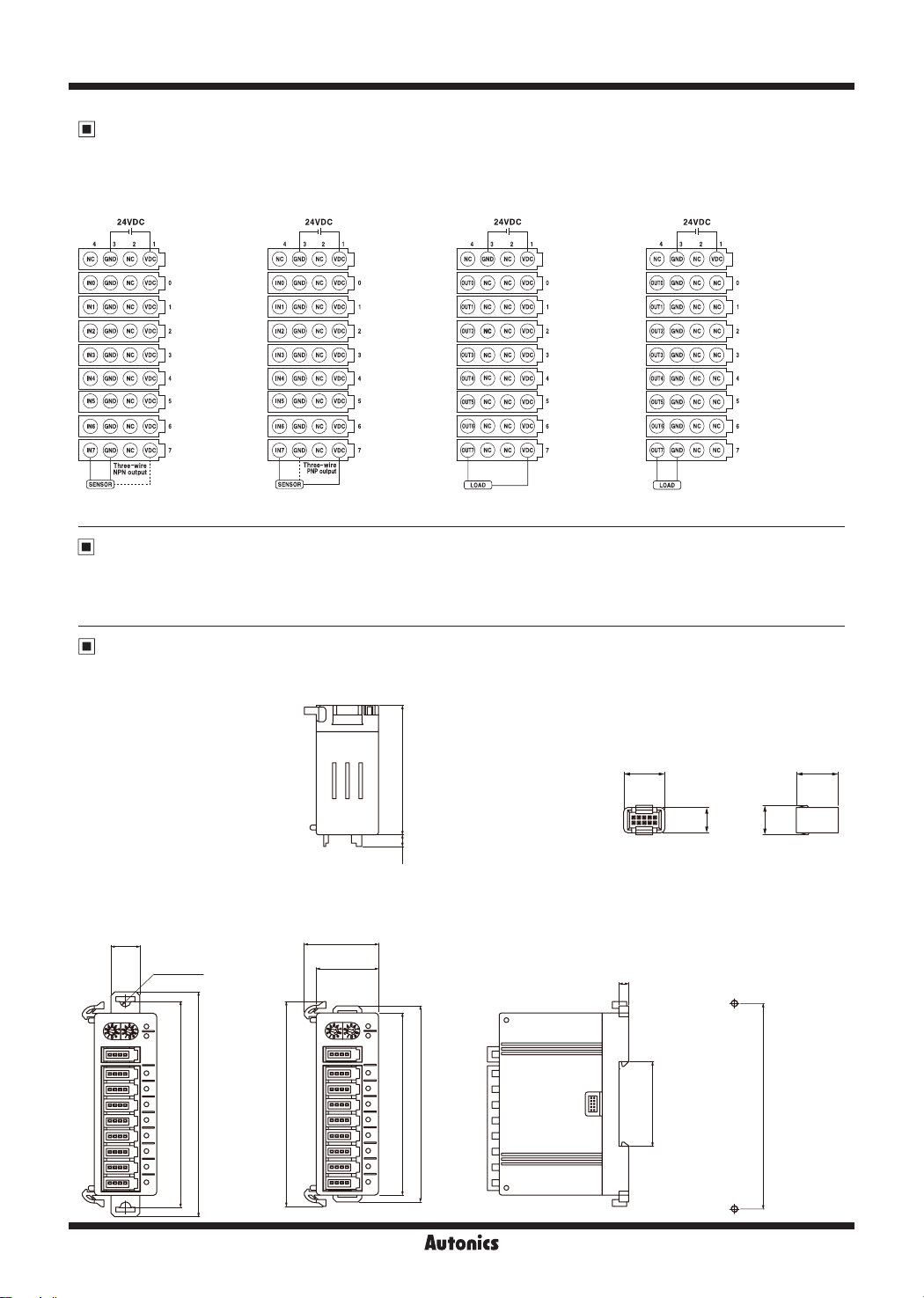
Connections
※
When wiring the communication connector, use AWG20 cable and tighten the connector screw with a tightening torque of 0.5N.m.
●ARM-DI08N-4S
●ARX-DI08N-4S
●ARM-DI08P-4S
●ARX-DI08P-4S
●ARM-DO08N-4S
●ARX-DO08N-4S
●ARM-DO08P-4S
●ARX-DO08P-4S
- +
IN(NPN): 8P, 24VDC 10mA
- +
IN(PNP): 8P, 24VDC 10mA
- +
OUT(NPN): 8P, 24VDC 0.3A/Point
- +
OUT(PNP): 8P, 24VDC 0.3A/Point
Terminating Resistance
● 120Ω ● 1% of metallic film ● 1/4W
※
Connect terminating resistances on the both ends of the network cables. If not connecting terminating resistances,
impedance can be too high or low. It may cause network problems.
Dimensions
※
Same dimensions are applied to both basic and expansion unit.
※
Tightening torque for mounting bolts: 1.8 to 2.5N·m
● Expansion connector
(supplied only for expansion unit)
54
9.8 10
(unit: mm)
● Rail lock position:
mounting with bolt
12
2-Ø4.5
86
X-38
93.8
4.9
● Rail lock position:
mounting on DIN rail
31
26
85.4
76
81.8
4
35mm DIN rail
6
●
Panel cut-out
7
86
Page 6
Modbus Digital Remote I/O
Setup and Installation
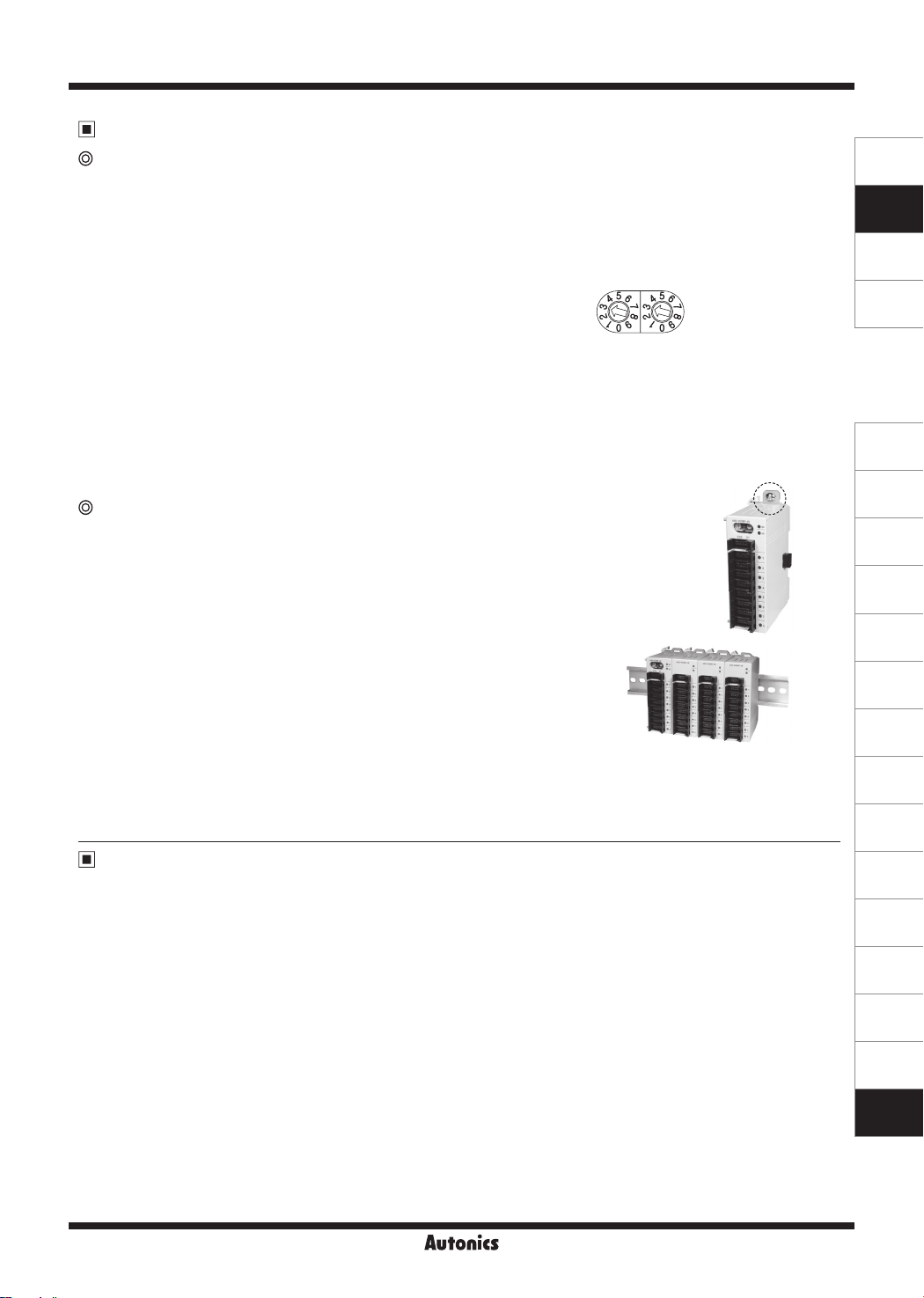
Setting node address
-Setting address is able to be done by rotary switch for address, or by in the EEPROM.
- If the rotary switch for address’ number is "00", the address is available to set by in the EEPROM.
The others, the desired number of rotary switch is that address.
- The address of the connected unit must not be duplicated.
When changing the address during operation, the unit status (MS) LED flashes in red and the unit communicates to
the address before the change.
● By rotary switch for address
Two rotary switches are used for setting address. The X10
①
switch represents tens digit and the X1 switch represents
ones digit. The address can be set 01 to 99.
② After setting the desired address, re-supply the unit power for
applying the changed address.
(E.g.)
X10 X1
The X10 and X1 switches point both at "3",
the address is "33".
SENSORS
CONTROLLERS
MOTION DEVICES
SOFTWARE
● By in the EEPROM for address
①During communicate status with master system (PLC or PL), set the desired address on the 41029 EEPROM MAC ID
parameter.
②The set address is changed after unit power is supplied. Re-supply the unit power for applying the changed address.
Unit Installation
● Mounting on panel
Pull two Rail locks on the rear part of a unit, there is a fixing bolt hole.
①
Place unit on a panel to be mounted.
②
Make a hole on a fixing bolt hole position.
③
Fasten the bolt to fix the unit tightly. Please set the tightening torque under 0.5N·m.
④
● Mounting on DIN rail
Pull two Rail locks on the rear part of a unit.
①
Place the unit on DIN rail to be mounted.
②
Press Rail locks to fix the unit tightly.
③
● Connection of basic and expansion units
Turn OFF the power of a basic unit.
①
Remove the cover of connector for extension with nippers.
②
Connect connector input part of an expansion unit and connector output part of
③
a basic unit with the connector which is enclosed with an expansion unit box.
Connected expansion units are installed as the right figure.
④
Supply power to the basic unit.
⑤
※
Re-supply power to the basic unit, and it recognizes expansion units.
Cautions during Use
1. Follow instructions in 'Cautions during Use'. Otherwise, it may cause unexpected accidents.
2. 24VDC power supply should be insulated and limited voltage/current or Class 2, SELV power supply device.
3. Use only designated connector and do not apply excessive power when connecting or disconnecting the connectors.
4. Keep away from high voltage lines or power lines to prevent inductive noise. In case installing power line and input signal
line closely, use line filter or varistor at power line and shielded wire at input signal line. Do not use near the equipment
which generates strong magnetic force or high frequency noise.
5. Do not connect or disconnect the expansion unit when power is being supplied.
6. This unit may be used in the following environments.
Indoors (in the environment condition rated in 'Specifications')
①
Altitude max. 2,000m
②
Pollution degree 2
③
Installation category II
④
(J)
Temperature
Controllers
(K)
SSRs
(L)
Power
Controllers
(M)
Counters
(N)
Timers
(O)
Digital
Panel Meters
(P)
Indicators
(Q)
Converters
(R)
Digital
Display Units
(S)
Sensor
Controllers
(T)
Switching
Mode Power
Supplies
(U)
Recorders
(V)
HMIs
(W)
Panel PC
X-39
(X)
Field Network
Devices
 Loading...