


Programmable Counter/Timer
CT Series
User Manual
CT Series
CT Series

내
ii © Copyright Reserved Autonics Co., Ltd.

Preface
Thank you for purchasing Autonics product.
Please familiarize yourself with the information contained in the Safety Precautions section
before using this product.
This user manual contains information about the product and its proper use, and should be kept
in a place where it will be easy to access.
나 Preface
© Copyright Reserved Autonics Co., Ltd. iii

User Manual Guide 나
User Manual Guide
Please familiarize yourself with the informati on i n this manual before using the product.
This manual provides detailed information on the product's features. It does not offer any
guarantee concerning matters beyond the scope of t his manual.
This manual may not be edited or reproduced in eith er part or whole without permission.
A user manual is not provided as part of the product package. Visit our web site
(www.aut onics.com) to download a copy.
The manual's content may vary depending on changes to the product's software and other
unforeseen developments within Autonics, and is subject t o change without prior notice.
Upgrade notice is provided through out homepage.
We contrived to describe this manual more easily and correctly. However, if there are any
corrections or questions, please notify us these on our homepage.
iv © Copyright Reser ved Autonics Co., Ltd.

나 User Manual Symbols
User Manual Symbols
Symbol Description
※1
Supplementary information for a particular feature.
Failure to follow instructions can result in serious injury or death.
Failure to follow instructions can lead to a minor injury or product damage.
An example of the concerned feature's use.
Annotation mark.
© Copyright Reserved Autonics Co., Ltd. v

Safety Precautions 나
Safety Precautions
Following these safety precautions will ensure the safe and proper use of the product and
help prevent accidents, as well as minimizing possible hazards.
Safety precautions are categorized as Warnings and Cautions, as defined below:
Warning
Caution
Failure to follow these instructions may result in serious
injury or death.
Failure to follow these instructions may result in personal
injury or product damage.
Fail-safe device must be installed when using the unit with machinery that may cause
serious injury or substantial economic loss. (e.g. nuclear power control, medical equipment,
ships, vehicles, railways, aircraft, combustion apparatus, safety equipment, crime/disaster
prevention devices, etc.)
Failure to follow this instruction may result in personal injury, fire, or economic loss.
The unit must be installed on a device panel before use.
Failure to follow this instruction may result in elect ric shock.
Do not connect, repair, or inspect the unit while connected to a power source.
Failure to follow this instruction may result in electric shock.
Do not disassemble or modify the unit. Please cont act us if necessary.
Failure to follow this instruction may result in electric shock or fire.
Do not use the unit outdoors.
Failure to follow this instruction may result in shortening the life cycle of the unit, or electric
shock.
When connecting the power input and relay out put cables, use AWG20 (0.50mm
and make sure to tighten the terminal screw bolt ab ove 0.74N·m to 0.90N·m.
Failure to follow this instruction may result in fi re due to contact failure.
2
) cables
Use the unit within the rated specifications.
Failure to follow this instruction may result in shortening the life cycle of the unit, or fire.
Do not use loads beyond the rated switching capa cit y of the relay contact.
Failure to follow this instruction may result in insulat ion failure, contact melt, contact failure,
relay broken, or fire.
Do not use water or oil-based detergent w hen clean ing the unit. Use dry cloth to clean the un it.
Failure to follow this instruction may result in electric shock or fire.
Do not use the unit where flammable or explosive gas, humidity, direct sunlight, radiant heat,
vibration, or impact may be present.
Failure to follow this instruction may result in fi re or explosion.
Keep dust and wire residue from flowing into the unit.
Failure to follow this instruction may result in fi re or pr oduct damage.
The specifications and dimensions of user manual are subject to change and some
models may be discontinued without notice.
vi © Copyright Reserved Autonics Co., Ltd.

나 Cautions During Use
Cautions During Use
Power ON/OFF
The inner circuit voltage rises within 100ms after supplying the power to the unit.
The input is unavailable at this period. Be sure that the i nner circuit voltage drops
within 500ms after turning OFF the power.
In case of 24VAC / 24-48VDC model, power supply should be insulated and limited
voltage/current or Class 2 power supply device.
Input signal line
① Shorten the cable from the sens or t o the unit.
② Use shield cable when input cable is longer .
③ Wire the input signal line separat ely from power line.
Input logic selection
Before selecting input logic, must cut off the power to counter/timer. Select the input logic
following the instruction.
Contact counting input (counter operation)
If counting speed for counter is high speed mode (1k, 5k, 10kcps) and counting input is
contact, it may cause input signal error by chatt eri ng of contact switching.
Set counting speed as low speed mode (1cps or 30cps) for contact counting input.
T esting dielectric voltage or insulation resistance when the unit is installed at control panel
① Isolate the unit from the circuit of control panel.
② Short all terminals of the unit .
Do not use the unit in the following environments.
① Environments with high v i brat ion or shock.
② Environments with strong alk al i or strong acid materials
③ Environments with exposure to direct sunlight
④ Near machinery which produc e st rong magnetic force or electric noise
This product may be used in the following environments.
① Indoors
② Max. altitude: 2,000m
③ Pollution degree 2
④ Installation category II
Failure to follow these instructions may result in product damage.
© Copyright Reserved Autonics Co., Ltd. vii

Cautions During Use 나
viii © Copyright Reserved Autonics Co., Ltd.

나 Table of Contents
Table of Contents
Preface .......................................................................................................................... iii
User Manual Guide ....................................................................................................... iv
User Manual Symbols .................................................................................................... v
Safety Precautions ........................................................................................................ vi
Cautions During Use ..................................................................................................... vii
Table of Contents .......................................................................................................... ix
1 Product Overview ..................................................................................... 11
1.1 Features .......................................................................................................... 11
1.2 Components and Accessories ......................................................................... 11
1.2.1 Components ............................................................................................... 11
1.2.2 Sold separately .......................................................................................... 12
1.3 Ordering information ........................................................................................ 13
1.4 Part description ................................................................................................ 14
1.4.1 CTS Series ................................................................................................. 14
1.4.2 CTY Series ................................................................................................. 14
1.4.3 CTM Series ................................................................................................ 14
2 Specifications ............................................................................................ 17
3 Communication Specification .................................................................. 19
4 Dimensions ................................................................................................ 21
4.1 CTS Series ...................................................................................................... 21
4.2 CTY Series ...................................................................................................... 21
4.3 CTM Series ...................................................................................................... 21
4.4 Panel cut-out dimensions ................................................................................ 22
4.4.1 CTS Series ................................................................................................. 22
4.4.2 CTY Series ................................................................................................. 22
4.4.3 CTM Series ................................................................................................ 22
4.5 Bracket ............................................................................................................ 23
4.5.1 CTS Series ................................................................................................. 23
4.5.2 CTY Series ................................................................................................. 23
4.5.3 CTM Series ................................................................................................ 23
5 Guide For Connection .............................................................................. 25
5.1 Connections ..................................................................................................... 25
5.1.1 CTS Series ................................................................................................. 25
5.1.2 CTY Series ................................................................................................. 27
5.1.3 CTM Series ................................................................................................ 29
5.2 Input and Output connection ............................................................................ 32
5.2.1 Input logic selection [no-voltage(NPN)/voltage(PNP)] ............................. 32
5.2.2 Input connection ......................................................................................... 34
5.2.3 Output connection ...................................................................................... 35
© Copyright Reserved Autonics Co., Ltd. ix

Table of Contents 나
6 Basic Operations (Counter/Timer/Communication) ............................ 37
6.1 Operations and functions ................................................................................. 37
6.1.1 Setting value change mode (Counter/Timer) ............................................. 37
6.1.2 Setting value check mode .......................................................................... 38
6.1.3 Switching display function in preset indicator ............................................. 38
6.1.4 RESET ........................................................................................................ 38
6.2 BATCH counter (only for CT6M-1P□□/CT6M-2P□□ model) ................... 38
6.2.1 BATCH counter operation .......................................................................... 39
6.2.2 BATCH counting operation ........................................................................ 39
6.2.3 BATCH output operation ............................................................................ 39
6.2.4 BATCH RESET input ................................................................................. 39
6.2.5 Example of BATCH counter ....................................................................... 40
6.3 Setting mode ................................................................................................... 41
7 Counter Mode ............................................................................................ 43
7.1 Parameter Setting ............................................................................................ 43
7.2 Input mode ...................................................................................................... 45
7.3 Output mode .................................................................................................... 48
7.4 Counter operation for indicator model ............................................................. 51
7.5 Output operation for other conditions .............................................................. 52
7.5.1 Start point ................................................................................................... 52
7.5.2 When start point value is larger than setting val ue,
(UP, UP-1, UP-2, UD-A, UD-B, UD-C mode) ........................................... 52
7.5.3 When PRESET 1 is larger or equal than PRESET 2 at at down mode ..... 53
7.6 Prescale .......................................................................................................... 54
8 Timer Mode ................................................................................................ 55
8.1 Parameter setting ............................................................................................ 55
8.2 Output mode .................................................................................................... 57
8.3 Timer operation for indicator model ................................................................. 65
8.4 Timer ‘0’ Time Setting ...................................................................................... 68
8.4.1 Available output mode to set ‘0’ time setting .............................................. 68
8.4.2 Operation by each output mode (‘0’ time setting) ...................................... 68
9 Factory Default .......................................................................................... 75
9.1 Common .......................................................................................................... 75
9.2 Counter ............................................................................................................ 75
9.3 Timer ............................................................................................................... 76
x © Copyright Reserved Autonics Co., Ltd.

나 1 Product Overview
1 Product Overview
1.1 Features
Prescale value setting range
- 6-digit model: 0.00001 to 99999.9/ 4-digit model: 0.001 to 999.9
Communication function supported (communication model): RS485 (Modbus RTU)
One-shot output time setting range: 0.01 sec to 99.99 sec by setting per 10ms
[Counter]
9 input modes/ 11 output modes
BATCH counter, Count start point (counting initial value) setting function
[Timer]
13 output modes
Various time setting range
- 6-digit model: 0.001 sec to 99999.9 hour/
'0' time setting function
Selectable timer memory retention function for indicator model
4-digit model: 0.001 sec to 9999 hour
1.2 Components and Accessories
1.2.1 Components
Make sure all of the above components are included with your product package before use.
If a component is missing or damaged, please conta ct Autonics or your distributor.
© Copyright Reserved Autonics Co., Ltd. 11

1 Product Overview
1.2.2 Sold separately
(1) Communication converter
SCM-38I
(RS232C to RS485 converter)
(2) Display unit (DS/DA-T Series)
(RS485 communication input type display unit)
SCM-US48I
(USB to RS485 converter)
Connect RS485 communication input type display unit (DS/DA-T Series) and RS485
communication output model of CT Series, the display unit displays present val ue of the device
without PC/PLC.
12 © Copyright Reserved Autonics Co., Ltd.

나 1 Product Overview
6 M
4
②
③
⑤
⑥
Item
Description
1.3 Ordering information
CT
- 2P
T
①
① Item
② Display digit
③ Size
④ Output
⑤ Power supply
⑥ Communication
④
CT Counter/Timer
4 9999 (4-digit)
6 999999 (6-digit)
S DIN W48 × H48mm
Y DIN W72 × H36mm
M DIN W72 × H72mm
1P 1-stage preset
2P 2-stage preset
I※1
2 24VAC 50/60Hz, 24-48VDC
4 100-240VAC 50/60Hz
No-mark None
T RS485 communication output
Indicator
※1: CT4S model does not support indicator type.
© Copyright Reserved Autonics Co., Ltd. 13

1 Product Overview
1.4 Part description
1.4.1 CTS Series
1.4.2 CTY Series
1.4.3 CTM Series
14 © Copyright Reserved Autonics Co., Ltd.

나 1 Product Overview
Model
Changed
Note
① Counting value display component (red)
RUN mode: Displays counting value for counter operation or time progress value for timer
operation.
Setting mode: Displays parameter.
② Setting value display component (green)
RUN mode: Displays setting value.
Setting mode: Displays parameter setting value.
③ Key lock indicator (LOCK): Turns ON for key lock setting.
④ Counter indicator (CNT): Turns ON for counter operation.
⑤ Timer indicator (TMR): Flashes (progressing time) or Turns ON (stoping time) for timer
operation.
⑥ Setting value checking and changing indicator (PRESET1, PRESET2)
: Turns ON when checking and changing setting value.
⑦ Output indicator (OUT1, OUT2): Turns ON for the dedicated control output ON.
⑧ key
RUN mode: Press the key to reset the counting value.
BATCH counter mode (CTM Series)
: Press the
⑨ key
RUN mode: Enters parameter setting mode or communication setting mode.
Setting mode: Saves setting value and return to RUN mode.
⑩
⑪ key
⑫ BATCH output indicator (BA.O) (red)
⑬ BATCH setting value checking and changing indicator (BA.S) (green)
, ,
- key
RUN mode: Enters setting value change mode.
Setting value change mode: Moves setting value digits.
- key
Setting value change mode, Setting mode: Changes setting value.
Setting value check mode: Checks setting value of the previous parameter.
- key
RUN mode: Enters setting value check mode.
Setting value change mode, Setting mode: Changes setting value.
Setting value check mode: Check setting value of the next parameter.
RUN mode: Enters BATCH counter indication mode.
: Turns ON when BATCH output is ON.
: Turns ON when checking or changing BATCH setting value.
key to reset the batch counting value.
CT4S-1P
CT6S-1P
CT6Y-1P
CT6M-1P
CT6S-I
CT6Y-I
CT6M-I
PRESET2 → PRESET
OUT2 → OUT
PRESET2 → PRESET
No PRESET1, OUT1 LEDs
No PRESET1, OUT1, OUT2 LEDs
No PRESET1, OUT1, OUT2, BA.S, BA.O LEDs.
No key.
※ CT4S model does not support indicator type.
© Copyright Reserved Autonics Co., Ltd. 15

1 Product Overview
16 © Copyright Reserved Autonics Co., Ltd.

나 2 Specifications
Series
CTS
CTY
CTM
Counting value
6.5 × 10mm
4.5 × 10mm
4.2 × 9.5mm
6.6 × 13mm
counting speed
Decimal point
2 Specifications
1-stage preset
Model
Display digit 4-digit 6-digit 6-digit 6-digit
Display method 7-segment (counting value: red, setting value: green) LED method
Character
size
(W × H)
Power
supply
Permissible voltage range 90 to 110% of rated voltage
Power
consumption
Counter
Timer
Input method
One-shot output time 0.01s to 99.99s setting
2-stage preset
indicator
Setting value 4.5 × 8mm 3.5 × 7mm 3.5 × 7mm 5 × 9mm
AC voltage 100-240VAC 50/60Hz
AC/DC voltage 24VAC 50/60Hz, 24-48VDC
AC voltage Max. 12VA
AC/DC voltage AC: Max. 10VA, DC: Max. 8W
INA/INB max.
Counting range -999 to 9999 -99999 to 999999
Scale
Min. signal width RESET signal: Selectable 1ms/20ms
Time
range
Operation method Count up, Count down, Count up/down
Min. signal width INA, INH, RESET signal: Selectable 1ms/20ms
Repeat error
SET error
Voltage error
Temperature error
4-digit 9.999s, 99.99s, 999.9s, 9999s, 99m59s, 999.9m, 9999m, 99h59m, 9999h
6-digit
CT4S-1P□□ CT6S-1P□□ CT6Y-1P□□ CT6M-1P□□
CT4S-2P□□ CT6S-2P□□ CT6Y-2P□□ CT6M-2P□□
-
Selectable 1cps/30cps/1kcps/5kcps/10kcps
up to third digit
999.999s, 9999.99s, 99999.9s, 999999s, 99m59.99s, 999m59.9s, 9999m59s,
99999.9m, 999999m, 99h59m59s, 9999h59m, 99999.9h
In case of power ON start: Max. ±0.01% ±0.05s
In case of signal ON start: Max. ±0.01% ±0.03s
Selectable voltage input or no-voltage input
[Voltage input]-input impedance: 5.4kΩ, [H]: 5-30VDC, [L]: 0-2VDC
[No-voltage input]-short-circuit impedance: Max. 1kΩ, short-circuit residual
CT6S-I□□ CT6Y-I□□ CT6M-I□□
Decimal point up to fifth digit
INA, INHIBIT,
RESET, BATCH
RESET signal:
Selectable 1ms /
20ms
voltage: Max. 2VDC
© Copyright Reserved Autonics Co., Ltd. 17

2 Specifications
(1c): 1
Series CTS CTY CTM
Model
1-stage preset
2-stage presert
Indicator
CT4S-1P□□
CT4S-2P□□
-
CT6S-1P□□ CT6Y-1P□□ CT6M-1P□□
CT6S-2P□□ CT6Y-2P□□ CT6M-2P□□
CT6S-I□□ CT6Y-I□□ CT6M-I□□
Standard Comm. Standard Comm. Standard Comm.
1-stage
SPDT(1c): 1 SPDT(1c) : 1 SPDT(1c) : 1
SPST
Contact
(Relay)
Control
output
Solid
state
(NPN
open
collector)
Type
Capacity
Type
Capacity
External power supply
2-stage
1-stage
2-stage
SPST(1a): 2
250VAC 5A resistive load
1
-
Max. 30VDC, 100mA
Max. 12VDC ±10%, 100mA
(1a): 1,
SPDT
250VAC 3A
resistive load
1
SPST
(1a): 2
1 2
-
SPST(1a): 1,
SPDT(1c): 1
250VAC 5A
resistive load
3
2
Memory retention Approx. 10 years (non-volatile memory)
Insulation resistance
Over 100MΩ (at 500VDC megger)
Dielectric strength 2,000VAC 50/60Hz for 1 min
Noise
immunity
Vibration
AC voltage
AC/DC voltage
Mechanical
Malfunction
Mechanical
Square-wave noise by noise simulator (pulse width 1µs) ±2kV
Square-wave noise by noise simulator (pulse width 1µs) ±500V
0.75mm amplitude at frequency of 10 to 55Hz (for 1 min) in each
X, Y, Z direction for 1 hour
0.5mm amplitude at frequency of 10 to 55Hz (for 1 min) in each X, Y, Z
direction for 10 minutes
300m/s² (approx. 30G) in each X, Y, Z direction for 3 times
Shock
Relay
life cycle
Malfunction
Mechanical Min. 10,000,000 operations
Malfunction Min. 100,000 operations
100m/s² (approx. 10G) in each X, Y, Z direction for 3 times
Protection structure Front part: IP65 (IEC standards)
Environ-
ment
Ambient temp.
Ambient humi. 35 to 85% RH, storage: 35 to 85% RH
-10 to 55℃, storage: -25 to 65℃
Approval
Weight※1
※
1: The weight includes packaging. The weight in parentheses is for unit only.
※
Environment resistance is rated at no freezing or condensation.
Approx. 212g
(approx. 159g)
Approx. 228g
(approx. 140g)
Approx. 322g
(approx. 252g)
18 © Copyright Reserved Autonics Co., Ltd.

나 3 Communication Specification
3 Communication Specification
Comm. protocol Modbus RTU (16bit CRC)
Connection type RS485
Application standard Compliance with EIA RS485
Max. connection 31 units (address: 1 to 127)
Synchronous method Asynchronous
Comm. type Two-wire half duplex (half duplex)
Comm. distance Max. 800m
Comm. speed 2400, 4800, 9600 (factory default), 19200, 38400bps
Comm. response time 5 to 99ms (factory default: 20ms)
Start bit 1-bit (fixed)
Data bit 8-bit (fixed)
Parity bit None (factory default), Even, Odd
Stop bit 1, 2-bit (factory default: 2bit)
It is recommended to use communication converter RS232C to RS485 (SCM-38I, sold
separately), USB to RS485 (SCM-US48I, sold separately). Communication cable should be
twisted pair cable for RS485 communication.
© Copyright Reserved Autonics Co., Ltd. 19

3 Communication Specification
20 © Copyright Reserved Autonics Co., Ltd.

4 Dimensions
4.1 CTS Series
4.2 CTY Series
나 4 Dimensions
(unit: mm)
4.3 CTM Series
© Copyright Reserved Autonics Co., Ltd. 21

4 Dimensions
4.4 Panel cut-out dimensions
(unit: mm)
4.4.1 CTS Series
4.4.2 CTY Series
4.4.3 CTM Series
22 © Copyright Reserved Autonics Co., Ltd.

4.5 Bracket
4.5.1 CTS Series
4.5.2 CTY Series
나 4 Dimensions
(unit: mm)
4.5.3 CTM Series
© Copyright Reserved Autonics Co., Ltd. 23

4 Dimensions
24 © Copyright Reserved Autonics Co., Ltd.

나 5 Guide For Connecti on
5 Guide For Connection
5.1 Connections
5.1.1 CTS Series
(1) CT□S-1P□
(2) CT□S-1P□T
(3) CT□S-2P□
© Copyright Reserved Autonics Co., Ltd. 25

5 Guide For Connection
(4) CT□S-2P□T
(5) CT6S-I□
(6) CT6S-I□T
Be sure that connection is varied by supporting RS485 communication.
※1: AC voltage: 100-240VAC 50/60Hz
AC/DC voltage: 24-48VDC, 24VAC 50/60Hz
※2: Counter operation: If INHIBIT sig nal is applied, count input will be prohibited.
Timer operation: If INHIBI T signal is applied, time progressing will stop.(HOLD)
26 © Copyright Reserved Autonics Co., Ltd.

나 5 Guide For Connecti on
5.1.2 CTY Series
(1) CT6Y-1P□
(2) CT6Y-1P□T
(3) CT6Y-2P□
© Copyright Reserved Autonics Co., Ltd. 27

5 Guide For Connection
(4) CT6Y-2P□T
(5) CT6Y-I□
(6) CT6Y-I□T
Be sure that connection is varied by supporting RS485 communication.
※1: AC voltage: 100-240VAC 50/60Hz
AC/DC voltage: 24-48VDC, 24VAC 50/60Hz
※2: Counter operation: If INHIBIT sig nal is applied, count input will be prohibited.
Timer operation: If INHIBIT signal is applied, time progressing will stop.(HO LD)
28 © Copyright Reserved Autonics Co., Ltd.

나 5 Guide For Connecti on
5.1.3 CTM Series
(1) CT6M-1P□
(2) CT6M-1P□T
© Copyright Reserved Autonics Co., Ltd. 29

5 Guide For Connection
(3) CT6M-2P□
(4) CT6M-2P□T
Be sure that connection is varied by supporting RS485 communication.
※1: AC voltage: 100-240VAC 50/60Hz
AC/DC voltage: 24-48VDC, 24VAC 50/60Hz
※2: Counter operation: If INHIBIT sig nal is applied, count input will be prohibited.
Timer operation: If INHIBIT signal is applied, time progressing will stop.(HO LD)
30 © Copyright Reserved Autonics Co., Ltd.

나 5 Guide For Connecti on
(5) CT6M-I□
(6) CT6M-I□T
Be sure that connection is varied by supporting RS485 communication.
※1: AC voltage: 100-240VAC 50/60Hz
AC/DC voltage: 24-48VDC, 24VAC 50/60Hz
※2: Counter operation: If INHIBIT signal is applied, count input will be prohibited.
Timer operation: If INHIBIT signal is applied, time progressing will stop.(HOLD)
© Copyright Reserved Autonics Co., Ltd. 31

5 Guide For Connection
5.2 Input and Output connectio n
5.2.1 Input logic selection [no-voltage(NPN)/voltage(PNP)]
1. The power must be cut OFF.
2. Squeeze toward ① and pull toward ② as the figure. (CTS/CTY Series)
3. Select input logic by using input logic switch (SW1 ) inside Counter/Timer.
4. Push a case in the opposite direction of ②.
5. Then supply the power to counter/timer.
32 © Copyright Reserved Autonics Co., Ltd.

나 5 Guide For Connecti on
(1) CTS Series
(2) CTY Series
(3) CTM Series
Turn OFF the power to select or change input logic (PNP/NPN).
© Copyright Reserved Autonics Co., Ltd. 33

5 Guide For Connection
5.2.2 Input connection
(1) No-voltage input (NPN)
Solid state input (standard sensor: NPN output type sensor)
Contact input
(2) Voltage input (PNP)
Solid state input (standard sensor: PNP output type sensor)
Contact input
※1: INA, INB/INH, RESET, INHIBIT, BATCH RESET input part
※2: For contact input, counting speed should be set 1cps or 30cps. (Counter)
34 © Copyright Reserved Autonics Co., Ltd.

나 5 Guide For Connecti on
5.2.3 Output connection
(1) Contact output
Select the load which capacity is not over contact cap acity.
(2) S olid state output
For solid state output, select load power and load not to be over (max. 30VDC, 100mA),
switching capacity.
Do not supply reverse polarity voltage.
※1: For using inductive load (relay, etc), connect surge absorber (diode, varistor, etc) at the both
ends of load.
© Copyright Reserved Autonics Co., Ltd. 35

5 Guide For Connection
36 © Copyright Reserved Autonics Co., Ltd.

6 Basic Operations (Counter/Timer/Co mmunication)
6 Basic Operations (Counter/Timer/Communication)
6.1 Operations and functions
※1: If no key is touched for 60 sec,the counter will return t o RUN mode without being restored
setting value in setting value change mode.
6.1.1 Setting value change mode (Counter/Timer)
In RUN mode, press the key to enter setting value chang e m ode.
Even if changing the setting value, input operation and output control will continue. In
addition, the setting value could be set to 0 and the output of 0 setting value turn s ON.
When entering the setting value change mode, the counting value display component
displays present value and the setting value display c om ponent displays the setting value.
According to the output mode, setting value could not be set to 0. (When setting to 0,
setting value "0" will flash 3 times.)
※In case of 1-stage preset, indicator model, PRESET2 displays PS and PRESET1 does not
displayed.
※Press the key to save the changing setting value at each parameter and it moves the next
parameter or returns in RUN mode.
© Copyright Reserved Autonics Co., Ltd. 37

6 Basic Operations (Counter/Timer/Communication)
6.1.2 Setting value check mode
Setting value of setting mode can be confirmed using the and keys.
6.1.3 Switching display function in preset indicator
Setting value 1(PS1) and setting value 2(PS2) are displayed each time pressing key in dual
setting value change model. (In timer, it is available for OND, ONd1, ONd2 output mode.)
6.1.4 RESET
In RUN mode or function setting mode, if pressing key or applying the signal to the RESET
terminal on the back side, present value will be reset and output will maintain off status. When
selecting voltage input (PNP), short no.10 and no. 12 terminals, or when selecting no-voltage
input (NPN), short no.11 and no.12 terminals to reset.
6.2 BATCH counter (only for CT6M-1P□□/CT6M-2P□□ model)
BATCH counter displays the repeat same operation to the set ting value.
In RUN mode, press the key to enter BATCH counter indication mode.
In BATCH counter indication mode, 'BATCH counter value' is displayed in count indicator
and 'BATCH counter setting value' is displayed in preset indicator.
In BATCH counter indication mode, press the key to set BATCH setting value change
mode.
Press the key to return BATCH counter indication mode.
※If setting BATCH counter setting value as ‘0’, BATCH output does not turn ON.
※In BATCH counter indication mode, press the key to return RUN mode.
38 © Copyright Reserved Autonics Co., Ltd.

6.2.1 BATCH counter operation
6.2.2 BATCH counting operation
BATCH counting value is increasing until BATCH reset signal applied. BATCH counting
value will be circulated when it is over 999999.
BATCH counting operation in Counter: Counts the number of reaching setting value.
BATCH counting operation in Timer: Counts the number of reaching sett ing t i m e. (in case of
'FLK' output mode, it counts the number of reaching T.off setting time and T.on setting time.)
6 Basic Operations (Counter/Timer/Co mmunication)
6.2.3 BATCH output operation
If input signal is applied while changing BATCH setting value, counting operation and output
control will be performed.
If BATCH count value equals to BATCH setting value, BATCH output will be ON and
maintain ON status until BATCH reset signal is applied.
When the power is cut off then resupplied in status of BATCH output is ON, BATCH output
maintains ON status until BATCH reset signal is applied.
※In case of from ‘BATCH setting value>BATCH counting value’ to ‘BATCH setting
value≤BATCH counting value’ and returning to RUN mode, BATCH output turns ON.
※In case of from turning ON BATCH output to ‘BATCH setting value>BATCH counting value’,
BATCH output maintains ON until BATCH RESET input applied.
6.2.4 BATCH RESET input In BATCH counter indication mode, press the key or applying the signal to BATCH
reset terminal on the back side panel, BATCH counting value will be reset.
When selecting voltage input (PNP), short termi nals 10 and 14, or when selecting
no-voltage input (NPN), short terminals 11 and 14 to reset.
When BATCH reset is applied, BATCH countin g value maintains at 0 and BATCH output
maintains in the OFF status.
© Copyright Reserved Autonics Co., Ltd. 39

6 Basic Operations (Counter/Timer/Communication)
6.2.5 Example of BATCH counter
(1) Counter
In case, putting 5 products in a box then packing the boxes when they reach to 200.
Counter setting: Preset setting value=5, BATCH setting value =200
When the count value of counter reaches to the setting value "5", the control output
(OUT) will be on, and at this time the count value of the B ATCH counter will be
increased by "1". The control box which is re ceived the control output (OUT) repeatedly
controls conveyor to move the full box and to place t he next empty box for standby.
When the BATCH count value reaches to "200", BATCH output will be ON. Then the
control box stops conveyor and provides a control signal for packing.
(2) Timer
Fills milk into the bottle for 3 sec (setting time) When 500 bottles ar e filled, BATCH counting
finish lamp is turned on.
(setting time: 3 sec, BATCH setting value: 500)
40 © Copyright Reserved Autonics Co., Ltd.

6.3 Setting mode
In RUN mode, hold the key for 3 sec/5 sec to enter parameter 1 group, parameter 2
group.
In setting mode, hold the key for 3 sec to return RUN mode.
6 Basic Operations (Counter/Timer/Communication)
※Counter counting and output control operates c ontinuously even entering setting mode.
※When changing the setting values of parameter 1 group via communication, the display value
and output are reset.
※Parameter 2 group is not available to non-communication models.
© Copyright Reserved Autonics Co., Ltd. 41

6 Basic Operations (Counter/Timer/Communication)
42 © Copyright Reserved Autonics Co., Ltd.

7 Counter Mode
(fixed as HOLD)
7.1 Parameter Setting
( key: Moves parameters, , key: changes parameter setti ng value)
Parameter Parameter setting value
7 Counter Mode
Counter/Timer
[C-T]
Input mode
[IN]
Output mode
[OUtM]
Indication mode
[DSpM]
Max. counting
speed [
CPS
]
TIME: Timer
● Input mode is UP, UP-1, UP-2 or DN, DN-1, DN-2,
※COUN: Counter
● Input mode is UD-A, UD-B, UD-C,
※ If max. counting speed is 5kcps or 10kcps, and output mode is D,
max. counting speed is automatically changed as 30cps, factory default.
● In case of indicator model,
※In case of the indicator type, indicate mode selection [DSP. M] is displayed.
※It is the added function to set the setting value when selecting HOLD.
※Max. counting speed is when duty ratio of INA or INB input signal is 1:1.
It is applied for INA, or INB input as same.
※When output mode is D, set max . counting speed one among 1cps, 30cps, or
1kcps.
OUT2 output
※1
time
[OUT2]
OUT1 output
※1
time
[
]
OUT1
OUT output
※1
[OUtT]
time
Decimal point
[DP]
※Set one-shot output time of OUT2.
※Setting range: 0.01 to 99.99 sec
※
When output mode is F, N, S, T, D, OUT2 does not appear.
※Set one-shot output time of OUT1.
※Setting range: 0.01 to 99.99 sec, Hold
※When 1st digit is flashing, press the key once and HOLD appears.
※When output mode is S, T, D, OUT1 does not appear. (fixed as HOLD)
※Setting range: 0.01 to 99.99 sec
※When output mode is F, N, S, T, D, OUtT does not appear. (fixed as HOLD)
● 6-digit model
※2
● 4-digit model
※Decimal point is applied to counting value and setting value.
© Copyright Reserved Autonics Co., Ltd. 43

7 Counter Mode
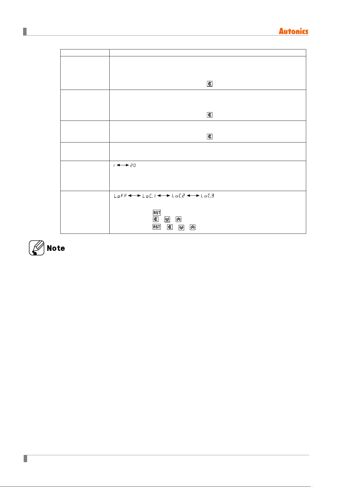
Parameter Parameter setting value
Min. reset time
[RST]
Input logic
[SIG]
Prescale
decimal point
※2
[ScDP]
Prescale value
[SCL]
Start point
value
[STRT]
Memory
protection
[DATA]
, unit: ms
※Set min. width of external reset signal input.
NPN: no-voltage input, PNP: voltage input
※Check input logic (NPN, PNP).
● 6-digit model
● 4-digit model
※Decimal point of prescale should not set smaller than decimal point [DP].
※Setting range of prescale value
6-digit model: 0.00001 to 99999.9, 4-digit model: 0.001 to 999.9
※Setting range is linked with decimal point [DP].
6-digit model: 0.00000 to 999999, 4-digit model: 0.000 to 9999
※When input mode is DN, DN-1, DN-2, start point value does not appear.
※CLR: Resets the counting value when power OFF.
REC: Maintains the counting value when power OFF. (memory protection)
lOFF: Unlock keys, key lock indicator turns OFF
Key lock
[LOCK]
※
LOc1: Locks key, key lock indicator turns ON
LOc2: Locks
LOc3: Locks ,
, ,
, ,
keys, key lock indicator turns ON
keys, key lock indicator turns ON
※1: For 1-stage setting value change model, OUT1 does not appear. The output time of OUT2 is
displayed as OUtT.
※2: Decimal point and prescale decimal point
Decimal point: Set the decimal point for display value regardless of prescale v alue.
Prescale decimal point: Set the decimal point for prescale value of counting value
regardless of decimal point of display value.
44 © Copyright Reserved Autonics Co., Ltd.

7.2 Input mode
Input
mode
Counting chart
Up
[UP]
※When INA is counting input, INB is no counting input.
When INB is counting input, INA is no counting input.
Up-1
[
]
UP-1
7 Counter Mode
Up-2
[
UP-2
Down
[DN]
※When INA input signal is rising ( ), it counts.
※INA: Counting input
※INB: No counting input
]
※When INA input signal is falling ( ), it counts.
※INA: Counting input
※INB: No counting input
※When INA is counting input, INB is no counting input.
When INB is counting input, INA is no counting input.
© Copyright Reserved Autonics Co., Ltd. 45

7 Counter Mode
Input
mode
it maintains previous counting value.
Counting chart
Down-1
[DN-1]
※When INA input signal is rising ( ) , it counts.
※INA: Counting input
※INB: No counting input
Down-2
[
DN-2]
Up/
Down-A
[UD-A]
※When INA input signal is falling ( ) , it counts.
※INA: Counting input
※INB: No counting input
※INA: Counting input
INB: Counting command input
※When INB is "L", counting command is up.
When INB is "H", it is counting command is down .
Up/
Down-B
[UD-B]
46 © Copyright Reserved Autonics Co., Ltd.
※INA: Up counting input
INB: Down counting input
※
INA: When INA and INB input signals are rising ( ) at the same time,

Input
mode
Counting chart
Up/
Down-C
[UD-C]
※When connecting encoder output A, B phase with counter input, INA, INB, set input
mode [InM] as phase different input [UD-C] for counter operation.
※ : over min. signal width, : over than 1/2 of min. signal width.
If the signal is smaller than these width, it may cause counting error (±1)
※The meaning of "H", "L"
7 Counter Mode
Input method
Character
H 5-30VDC Short
L 0-2VDC Open
※Min. signal width by counting speed (1cps = 1Hz)
Counting speed Min. signal width
1cps 500ms
30cps 16.7ms
1kcps 0.5ms
5kcps 0.1ms
10kcps 0.05ms
Voltage input
(PNP)
No-voltage input
(NPN)
© Copyright Reserved Autonics Co., Ltd. 47

7 Counter Mode
Input mode
counting display value increases or decreases until reset signal is
up, counting display value and retained output are maintained until
reset signal is applied.
7.3 Output mode
Output
mode
Up, Up-1, 2 Down, Down-1, 2
Up/Down A, B, C
F [F]
N [N]
※After count-up,
applied and retained output is maintained.
※After count-
C [C]
R [R]
※When count-up, counting display value will be reset and count simultaneously.
※OUT1 retained output will be off after OUT2 one- shot time.
※The one-shot output time of OUT1 one-shot output time is operated regardless
of OUT2 output.
※After count-up, counting value display is reset after one-shot output time of OUT2
and it counts simultaneously.
※OUT1 retained output will be off after OUT2 one-shot time.
※OUT1 one-shot output time is operated regardless of OUT2 output.
48 © Copyright Reserved Autonics Co., Ltd.

Output
Input mode
mode
Up, Up-1, 2 Down, Down-1, 2
7 Counter Mode
Up/Down A, B, C
K [K]
P [P]
※After count-up, counting display value increases or decreases until RESET input is
applied.
※OUT1 retained output is off after OUT2 one-shot time.
※OUT1 one-shot output time is operated regardless of OUT2 output.
※After count-up, counting dis play value is m aintained while OUT2 outpu t is on.
Counting value is internally reset a nd counts simultan eousl y.
※When OUT2 output is off, displays counting value while OUT2 is ON,
and it increases or decreases.
※OUT1 retained output is off after OUT2 one-shot time.
※OUT1 one-shot output time is operated regardless of OUT2 output.
Q [Q]
※After count-up, counting display value increases or decreases during OUT2
one-shot time.
※OUT1 retained output is off after OUT2 one-shot time.
※OUT1 one-shot output time is operated regardless of OUT2 output.
A [A]
.
※After count-up, counting display value and OUT1 retained output are maintained
until RESET input is applied.
※OUT1 one-shot output time is operated regardless of OUT2 output.
© Copyright Reserved Autonics Co., Ltd. 49

7 Counter Mode
≧
≧
≧
Output
mode
S [S]
Up/Down A, B, C
※OUT1 and OUT2 keep ON status in following condition:
Counting display value
Counting display value
PRESET1
PRESET2
T [T]
D [D]
※OUT1 output is off: Counting display value ≧ PRESET1
(when PRESET 1 is 0, OUT1 output maintains ON state.)
※
OUT2 keeps ON status in following condition:
Counting display value
PRESET2
※When counting display value is equal to setting value [PRESET1, PRESET2)
only, OUT1 or OUT2 output keeps ON status.
※When setting 1kcps for counting speed, solid state contact output should
be used.
(When using contact output, it is difficult to execute normal output operation due
to contact reaction time.)
※OUT output as 1-stage setting value change model operates as output of OUT 2 as 2-stage
setting value change model.
※In case of 2-stage setting value change model, OUT1 output operates as as one-shot output or
retained output. (except S, T, D mode)
※OUT1 output is available to set as ‘0’ at every output mode. The output for ‘0’ setting executes.
※In case of C[C], R[R], P[P], Q[Q] output mode, OUT2 output is not available to set as ‘0’.
50 © Copyright Reserved Autonics Co., Ltd.

7.4 Counter operation for indicator model
DSpM
Counting chart
Down input mode
input is
※Only for indicator model.
Indication
mode
[
]
TOTAL
[TOTAL]
Up input mode
(Up, Up-1, Up-2)
Count value increases or decreases until RESET input is applied.
When input is over max./min. counting value, it displays 0. When Reset input is applied,
it displays 0(Up)/999999(Down).
(Down, Down-1, Down-2)
7 Counter Mode
HOLD
[HOLD]
Count value increases or decreases until RESET input is applied. When input is
reaching setting value(Up)/0(Down), the display value is hold. When Reset
applied, it displays 0(Up)/setting value(Down).
※When the command input [UD-A], individual input [UD-B], phase difference input [UD-C] mode,
※In case of UP/DOWN [UD-A, UD-B, UD-C] input mode, indication mode [DSpM] parameter
does not appear.
© Copyright Reserved Autonics Co., Ltd. 51

7 Counter Mode
7.5 Output operation for other conditi on s
7.5.1 Start point
In case of counter operation, set start point [STRT] t o count from the set value.
It is not available for DN, DN-1, DN-2 input mode for count er.
When RESET input is applied, the present value i s r eset as start point value.
In case of C, R, P, Q output mode, it counts up and the present res et as start point value.
7.5.2 When start point value is larger t han setting value,
(UP, UP-1, UP-2, UD-A, UD-B, UD-C mode)
(1) PRESET2 > Start Point > PRESET1
UP, UP-1, UP-2 mode: Output of OUT1 does not execute.
When the present value counts as PRESET 2, output of OUT2 turns ON.
UD-A, UD-B, UD-C mode: When the present value counts down as PRESET 1, output
of OUT1 turns ON.
※Output mode: F
Input mode: UP, UP-1, UP-2
※Output mode: F
Input mode: UD-A, UD-B, UD-C
(2) PRESET2 > Start Point = PRESET1
In case of UP, UP-1, UP-2, UD-A, UD-B, UD-C mode, output of OUT1 turns ON when
RESET OFF.
52 © Copyright Reserved Autonics Co., Ltd.

7 Counter Mode
7.5.3 When PRESET 1 is larger or equal than PRESET 2 at at down
mode
(1) PRESET1 > PRESET2
Output of OUT1 does not execute.
(2) PRESET1=PRESET2
Output of OUT1 turns ON for RESET OFF.
© Copyright Reserved Autonics Co., Ltd. 53

7 Counter Mode
7.6 Prescale
This function is to set and display calculated unit for actual length, liquid, position, etc. It i s called
“prescale value” for measured length, liquid, or posit ion, etc per 1 pulse. For example, when
moving L, the desired length to be measured, and P, the number of pulses per 1 revolution of a
rotary encoder, occurs, prescale value is L/P.
Positioning control by counter and encoder
[ Diameter (D) of pulley connected with encoder= 2 2mm,
the number of pulses by 1 rotation of encoder=1,000]
Prescale value =
=
= 0.069mm/pulse
Set decimal point [DP] as [-----.-], prescale decimal point [sCDP] as [---.---], prescale
value [SCL] as [
0.1mm unit.
0.069
The number of pulses by 1 rotaiton of encoder
3.1416 ×22
1000
] at function setting mode. It is available to c ontrol conveyer position by
π × Diameter (D) of pulley
54 © Copyright Reserved Autonics Co., Ltd.

8 Timer Mode
Parameter
Parameter setting value
8.1 Parameter setting
( key: Moves parameters, , key: changes parameter setting value)
8 Timer Mode
Counter/Timer
[C-T]
Time range
[HOUR/MIN/ SEC]
● 6-digit model
● 4-digit model
※COUN: Counter
TIME: Timer
UP/DOWN mode
[U-D]
Indication mode
[DSpM]
Memory
protection
[DATA]
Output mode
[OUtM]
© Copyright Reserved Autonics Co., Ltd. 55
※UP: Time progresses from ‘0’ to the setting time.
DN: Time progresses from the setting time to ‘0’.
※Used for the indicator model only.
※It is added that the feature which set the setting time when selecting HOLD
or ONtD.
※Used for the indicator model only.
※CLR: Reset time value when power is off.
REC: Memorizes time value at the moment of power off.
8 Timer Mode
Parameter
Parameter setting value
OUT2 output
※Set one-shot output time of OUT2.
time
※1
[
OUT2
※Setting range: 0.01 to 99.99 sec, Hold
]
※When 1st digit is flashing, press the key once and HOLD appears.
OUT1 output
※1
time
[OUT1]
OUT output
※1
[OUtT]
time
Input logic
[SIG]
Input signal
time
[InT]
※Set one-shot output time of OUT1.
※Setting range: 0.01 to 99.99 sec, Hold
※When 1st digit is flashing, press the key once and HOLD appears.
※Setting range: 0.01 to 99.99 sec, Hold
※When 1st digit is flashing, press the key once and HOLD appears.
NPN: no-voltage input, PNP: voltage input
※Check input logic value (NPN, PNP).
, unit: ms
※CTS/CTY: Set min. width of INA, INH, RESET signal.
※CTM: Set min. width of INA, RESET, INHIBIT, BATCH RESET signal.
lOFF: Unlock keys, key lock indicator turns OFF
※
Key lock [LOCK]
LOc1: Locks key, key lock indicator turns ON
LOc2: Locks
LOc3: Locks ,
, ,
, ,
keys, key lock indicator turns ON
keys, key lock indicator turns ON
※1: When output mode is FLk1, FLk2, INTG and OND, ONd1, ONd2 of 1-stage setting value
change model, OUT1does not appear. The output time of OUT2 is displayed as OUtT.
When output mode is OND, ONd1, ONd2, INt2, OUT1 appears.
※2: INt2 mode is available only for 2-stage setting value change m odel.
56 © Copyright Reserved Autonics Co., Ltd.

8.2 Output mode
Output
mode
Time chart
Signal ON Delay (Power RESET)
OND
[OND]
8 Timer Mode
1) Time starts when INA signal turns ON.
2) When INA signal turns OFF, time resets.
3) When INA signal is ON: Power ON Time S tart is ope rated.
RESET OFF Time Start is operated.
OND.1
[ONd1]
4) Control output operates as retained or one-shot output.
Signal ON Delay 1 (Power RESET)
1) Time starts when INA signal turns ON.
2) When INA signal is ON: Power ON T ime S tart is ope rated
RESET OFF Time Start is operated.
3) Control output operates as retained or one-shot output.
4) Only first INA input signal is valid in case INA input signal is
repeatedly applied.
© Copyright Reserved Autonics Co., Ltd. 57

8 Timer Mode
Output
mode
Power ON Delay 2 (Power Hold)
Flicker (Power RESET)
Time chart
OND.2
[ONd2]
1) Power ON Time Start (There is no INA function.)
2) RESET ON: Time RESET
RESET ON→OFF: Time Start
3) Control output operates as retained or one-shot output.
4) It memorizes display value at the moment of power
OFF.
FLK
[FLK]
1) Time starts when INA signal turns on.
2) When INA signal is ON: Power ON Time S tart is ope rated.
RESET OFF Time Start is operated.
3) Control output operates as retained output, output turns
off for the T.off time and turns off for the T.off time and
turns on for the T.on time repeatedly.
Ta+Tb = T.off setting time
4) The T.on time and T.off time must be set individually.
5) In case of using the contact output, min. setting time
must be set over 100ms.
58 © Copyright Reserved Autonics Co., Ltd.

8 Timer Mode
Output
mode
must be set over 100ms.
FLK.1
[FLk1]
Time chart
Flicker 1 (Power RESET)
Hold output
1) Time starts when INA signal turns on.
2) When INA signal is ON: Power ON Time Start is operate d.
RESET OFF Time Start is operated.
3) Control output operates as retained output.
4) In case of using the contact output, min. setting time
One-shot output
1) Time starts when INA signal turns on.
2) When INA signal is ON: Power ON Time Start is operated.
RESET OFF Time Start is operated.
3) Control output operates as one-shot output.
4) In case of using the contact output, min. setting time must
be set over 100ms.
© Copyright Reserved Autonics Co., Ltd. 59

8 Timer Mode
Output
mode
Flicker 2 (Power Hold)
1) Time starts when INA signal turns ON and the display
Time chart
Hold output
value at the moment when power is off is memorized.
2) When INA signal is ON: Power ON Time Start is operated.
RESET OFF Time Start is operated.
3) Control output operates as retained output.
FLK.2
[FLk2]
4) Control output will be reversed when it reaches to setting
time. (At the initial start, OUT2 control output is OFF).
5) In case of using the contact output, min. setting time must
be set over 100ms.
One-shot output
1) Time starts when INA signal turns ON and the display
value at the moment when power is off is memorized.
2) When INA signal is ON: Power ON Time Start is operated.
RESET OFF Time Start is operated.
3) Control output operates as one-shot output.
4) In case of using the contact output, min. setting time must
be set over 100ms.
※Power RESET: There is no memory protection. (resets the display value when power is off)
※Power Hold: There is memory protection. (mem orizes the display value at the moment of
power off, indicates the memorized di splay value when power is resupplied.)
60 © Copyright Reserved Autonics Co., Ltd.

8 Timer Mode
Output
mode
INT
[INT]
Time chart
Interval (Power RESET)
1) Control output turns ON and time starts when INA signal
turns ON.
2) When INA signal is OFF, time is reset.
3) When INA signal is ON: Power ON Time St art is op erated.
RESET OFF Time Start is operated.
4) When it reaches setting time, indication value and control
output are reset automatically.
5) Control output is ON when time is progressing.
Interval 1 (Power RESET)
INT.1
[INt1]
1) Control output turns ON and time starts when INA signal turnsn
ON.
2) When INA signal is ON: Power ON Time St art is op erated.
RESET OFF Time Start is operated.
3) When it reaches setting time, indication value and control
output are reset automatically.
4) Control output is ON when time is progres sing.
5) INA input is ignored while time is progressing.
© Copyright Reserved Autonics Co., Ltd. 61

8 Timer Mode
Output
mode
1) Time starts when INA input is ON and resets when
1) If INA is ON, control output remains ON.
Time chart
Interval 2 (Power RESET)
INT.2
[INt2]
INA input is OFF.
2) INA input is ON, OUT1 output is ON during T1 (hold)
or t1.
3) When it reaches setting time1, display value resets
and OUT2 output is ON during T 2 (hold) or t2 output
time.
※Output turns OFF when reaching the setting time even if
one-shot time is longer than setting time.
Signal Off Delay1 (Power RESET)
OFD
[OFD]
(except when power is off and reset is on)
2) When INA signal is OFF, time processes.
When it reaches setting time, indication value and
control output are reset automatically.
※Power RESET: There is no memory protection. (resets the display value when power is off)
※Power Hold: There is memory protection. (mem orizes the display value at the moment of
power off, indicates the memorized display value when power is resupplied.)
62 © Copyright Reserved Autonics Co., Ltd.

8 Timer Mode
Output
mode
NFD
[NFD]
Time chart
On-Off Delay (Power RESET)
1) When INA input is ON, output is ON and time is
progressing, then output is OFF after On_Delay time.
2) When INA input is OFF, output is ON and ti me is
progressing, then output is OFF after Off_Delay ti me.
3) If INA input is OFF within On_Delay time, step 2 starts again.
4) If INA input is ON within Off_Delay time, step 1 st arts ag ain.
On-Off Delay1 (Power Hold)
NFD.1
[NFd1]
1) When INA input turns ON, time progresses and
output turns ON after On_Delay time.
2) When INA input turns OFF, time pro gresses an d
output turns OFF after Off_Delay time.
3) If INA input turns OFF within On_Delay time,
output will turn ON and step 2 operate.
4) If INA input turns ON within Off_Delay time,
output will turn OFF and step 1 operate.
© Copyright Reserved Autonics Co., Ltd. 63

8 Timer Mode
Output
mode
Time chart
Integration Time (Power RESET)
INTG
[INTG]
1) Time is progressing while INA input is ON.
2) Time progress stops while INA input is OFF.
3) When it reaches the setting time, output is ON.
※Power RESET: There is no memory protection. (resets the display value when power is off)
※Power Hold: There is memory protection. (mem orizes the display value at the moment of
power off, indicates the memorized display value when power is resupplied.)
64 © Copyright Reserved Autonics Co., Ltd.

8.3 Timer operation for indicator model
※Only for indicator model.
8 Timer Mode
TOTAL
[TOTAL]
When memory protection setting is OFF
1) Time starts when INA input is ON.
2) Setting value is initialized when Reset input is ON.
3) Time progress stops when INHIBIT input is ON.
4) Resets when power is OFF.
When memory protection setting is ON
1)Time starts when INA input is ON.
2) Setting value is initialized when Reset input is ON.
3) Time progress stops when INHIBIT input is ON.
4) Display value at the moment of power OFF is memorized.
© Copyright Reserved Autonics Co., Ltd. 65

8 Timer Mode
HOLD
[HOLD]
When memory protection setting is OFF
1) Time progresses when INA input is ON.
2) Time progress stops while INA input is OFF.
3) When time reaches setting time, display value will stop and flash.
4) When reset input is applied, display value is initialized.
5) Resets when power is OFF.
When memory protection setting is ON
1) Time progresses when INA input is ON.
2) Time progress stops while INA input is OFF.
3) When time reaches setting time, display value will stop and flash.
4) When reset input is applied, display value is initialized.
5) Display value the moment when power is OFF is memorized.
66 © Copyright Reserved Autonics Co., Ltd.

8 Timer Mode
display value flashes and operation stops until reset signal is applied.
On Time
Display
[ONtD]
When memory protection setting is OFF
※ON time indicate mode of INA input
1) Time reset start operates when INA input turns ON.
2) Time progress stops while INA input is OFF.
3) When time progress stops and power i s off, th e display value is initi alized.
4) If progress time is greater than setting time when INA input turns off,
When memory protection setting is ON
※ ON time indicate mode of INA input
1) Time reset start operates when INA input turns ON.
2) Time progress stops while INA input is OFF.
3) When time progress stops and power is off, the display value is memorized.
4) If progress time is greater than setting time when INA input turns off,
display value flashes and operation stops until reset signal is applied.
※TMR mark flashes during timer operating.
※TMR mark turn ON for timer stop or hold.
※The present value is zero blank format for highest unit.
E.g.)In case of time range is 99m59.99s and the present value is 00m04.05s, zero blank is
applied for the highest unit, minute. In case of the below digit of decimal point, zero blank
is not applied. Therefore, it displays “0.0$05”.
※In case of timer , it is available for PRESET to set as ‘0’ and the output operates.
© Copyright Reserved Autonics Co., Ltd. 67

8 Timer Mode
8.4 Timer ‘0’ Time Setting
8.4.1 Available output mode to s et ‘0’ time setting
OND, ONd1, ONd2, NFD, NFd1
8.4.2 Operation by each output mode (‘0’ time setting)
(1) OND (Signal ON Delay) mode [OND]
Setting time 1 is set as ‘0’.
1) UP mode
2) DOWN mode
Setting time 2 is set as ‘0’.
68 © Copyright Reserved Autonics Co., Ltd.

(2) OND.1 (Signal ON Delay 1) mode [OND.1]
Setting time 1 is set as ‘0’.
1) UP mode
2) DOWN mode
8 Timer Mode
Setting time 2 is set as ‘0’.
© Copyright Reserved Autonics Co., Ltd. 69

8 Timer Mode
(3) OND.2 (Power ON Delay 2) mode [OND.2]
Setting time 1 is set as ‘0’.
1) UP mode
2) DOWN mode
Setting time 2 is set as ‘0’.
70 © Copyright Reserved Autonics Co., Ltd.

(4) NFD (ON-OFF Delay) mode [NFD]
1) Off_Delay setting time 1 is set as ‘0’.
2) On_Delay setting time 1 is set as ‘0’.
8 Timer Mode
© Copyright Reserved Autonics Co., Ltd. 71

8 Timer Mode
(5) OFD.1 (ON-OFF Delay 1) mode [NFD.1]
1) Off_Delay setting time 1 is set as ‘0’.
2) On_Delay setting time 1 is set as ‘0’.
72 © Copyright Reserved Autonics Co., Ltd.

8 Timer Mode
(6) When setting value 1(PRESET 1) is greater than setting value 2(PRESET 2),
In case of OND[OND], OND.1[ONd1], OND.2[ONd2] output mode,
UP mode: Ti mer s etting v alu e 1 (PRE SET 1 ) is g reate r than setting value 2 (PRE SET 2),
OUT 1 output does not turn ON.
DOWN mode: Timer setting value 1 (PRESET 1) is greater than s etting value2 (PRES ET 2),
as setting value 2 (PRESET 2), OUT1 output turns ON immediately when
applied start signal.
1) OND (Signal On Delay) output mode
OUT1 output does not turn ON. The setting value 1(PRESET 1) is same
2) ONd1 (Signal ON Delay 1) output mode
3) ONd2 (Signal On Delay 2) output mode
© Copyright Reserved Autonics Co., Ltd. 73

1
74 © Copyright Reserved Autonics Co., Ltd.

9 Factory Default
9.1 Common
Parameter Factory default
LOCK lOFF
9 F actory Default
PRESET1
PRESET2
9.2 Counter
Parameter Factory default
IN UD-C
OUtM F
DSpM TOTAL
CPS 30
OUT2 [OUtT] HOLD (fixed)
OUT1 00.10
DP ------
RST 20
SIG NPN
1000
5000
ScDP
SCL
STRT 000000
DATA CLR
6-digit model
4-digit model
6-digit model
4-digit model
-.-----
-.---
1.00000
1.000
© Copyright Reserved Autonics Co., Ltd. 75

9 Factory Default
Parameter
Factory default
9.3 Timer
HOUR/MIN/SEC
U-D UP
DSpM TOTAL
DATA CLR
OUtM OND
OUT2[OUtT]
OUT1 00.10
SIG NPN
InT 20
6-digit model 0.001s-999.999s
4-digit model 0.001s-9.999s
HOLD
76 © Copyright Reserved Autonics Co., Ltd.

■ Major Products
·
Photoelectric Sensors·Fiber Optic Sensors·Door Sensors·Door Side Sensors·Area Sensors
·Proximity Sensors·Pressure Sensors·Connectors/Sockets·Rotary Encoders·Panel Meters
·Counters·Timers·Temperature Controllers·SSRs/Power Controllers·Sensor Controllers
·Graphic/Logic Panels·Temperature/Humidity Transducers·Switching Mode Power Supplies
·Stepper Motors/Drivers/Motion Controllers·I/O Terminal Blocks & Cables·Display Units
·Control Switches/Lamps/Buzzers·Field Network Devices·Tachometer/Pulse(Rate) Meters
·Laser Marking System(Fiber, CO2, Nd:YAG)·Laser Welding/Cutting System
■ Corporate Headquarters
18 Bansong-ro, 513 Beon-gil, Haeundae-gu, Busan, South Korea 48002
■ Overseas Business Headquarters
#402-303, Bucheon Techno Park, 655, Pyeongcheon-ro, Wonmi-gu, Bucheon, Gyeonggi-do,
South Korea 14502
Tel: 82-32-610-2730 / Fax: 82-32-329-0728 / E-mail: sales@autonics.com
■ Brazil − Autonics do Brasil Comercial Importadora Expor tadora Ltda
Tel: 55-11-2307-8480 / Fax: 55-11-2309-7784 / E-mail: comercial@autonics.com.br
■ China − Autonics electronic(Jiaxing) Corporation
Tel: 86-21-5422-5969 / Fax: 86-21-5422-5961 / E-mail: china@autonics.com
■ India − Autonics Automation India Private Limited
Tel: 91-22-2781-4305 / Fax: 91-22-2781-4518 / E-mail: india@autonics.com
■ Indonesia − PT. Autonics Indonesia
Tel: 62-21-8088-8814/5 / Fax: 62-21-8088-4442(4440) / E-mail: indonesia@autonics.com
■ Japan − Autonics Japan Corporation
Tel: 81-3-3950-3111 / Fax: 81-3-3950-3191 / E-mail: ja@autonics.com
■ Malaysia − Mal-Autonics Sensor Sdn. Bhd.
Tel: 60-3-7805-7190 / Fax: 60-3-7805-7193 / E-mail: malaysia@autonics.com
■ Mexico − Autonics Mexico S.A. DE C.V
Tel: 52-55-5207-0019 / Fax: 52-55-1663-0712 / E-mail: ventas@autonics.com
■ Russia − Autonics Corp. Russia Representative Office
Tel/Fax: 7-495-660-10-88 / E-mail: russia@autonics.com
■ Turkey − Autonics Otomasyon Ticaret Ltd. Sti.
Tel: 90-216-365-9117/3/4 / Fax: 90-216-365-9112 / E-mail: infotr@autonics.com
■ USA − Autonics USA, Inc.
Tel: 1-847-680-8160 / Fax: 1-847-680-8155 / E-mail: sales@autonicsusa.net
■ Vietnam − Cong Ty Tnhh Autonics Vina
Tel: 84-8-3771-2662 / Fax: 84-8-3771-2663 / E-mail: vietnam@autonics.com
Dimensions or specifications on this manual are subject to change and
some models may be discontinued without notice.
MCC-CTU1-V1.0-1609US
 Loading...