

Autonics CR SERIES Instruction Manual
DRW161147AB
Autonics
CAPACITIVE PROXIMITY SENSOR
(CYLINDRICAL AC, DC TYPE)
CR SERIES
I N S T R U C T I O N M A N U A L
Thank you for choosing our Autonics products.
Please read the following safety considerations before use.
Safety Considerations
Please observe all safety considerations for safe and proper product operation to avoid hazards.
※
※
symbol represents caution due to special circumstances in which hazards may occur.
Warning Failure to follow these instructions may result in serious injury or death.
Caution
Failure to follow these instructions may result in personal injury or product damage.
Warning
1. Fail-safe device must be installed when using the unit with machinery that may cause serious injury or substantial
economic loss. (e.g. nuclear power control, medical equipment, ships, vehicles, railways, aircraft, combustion
apparatus, safety equipment, crime/disaster prevention devices, etc.)
Failure to follow his instruc ion may result in re, personal injury, or economic loss.
2. Do not disassemble or modify the unit.
Failure to follow his instruc ion may result in electric shock or re.
3. Do not connect, repair, or inspect the unit while connected to a power source.
Failure to follow his instruc ion may result in electric shock or re.
4. Check 'Connections' before wiring.
Failure to follow his instruc ion may result in re.
Caution
1. Use the unit within the rated specications.
Failure to follow his instruc ion may result in re or product damage.
2. Use dry cloth to clean the unit, and do not use water or organic solvent.
Failure to follow his instruc ion may result in electric shock or re.
3. Do not use the unit in the place where ammable/explosive/corrosive gas, humidity, direct sunlight, radiant heat,
vibration, impact, or salinity may be present.
Failure to follow his instruc ion may result in re or explosion.
4. Do not supply power without load.
Failure to follow his instruc ion may result in re or product damage.
Ordering Information
C R D N
Shape
Item
Dimensions
● CR18-8 ● CR30-15
Ø26.5
24
Grounding
The sensing distance will be changed by grounding status of capacity proximity sensor and the target [50×50×1mm (iron)].
Please check the material when installing he sensor and selec ing the target.
● CR18 ● CR30
Ground condition (switch b) ON OFF
Operating distance (mm) 8 4
The above specications are subject to change and some models may be discontinued without notice.
※
Be sure to follow cautions written in the instruction manual and the technical descriptions (catalog,
※
homepage).
1530
~
Body size
t~
Output
Power supply
Sensing distance
71.8
53.3
M18×1
8
Target
Switch b
2000
___;--+-------------1
O Normally open
C Normally closed
N NPN normally open
N2 NPN normally closed
P PNP normally open
D 12-24VDC
A 100-240VAC
Number Standard sensing distance (unit: mm)
Number Diameter of head (unit: mm)
R Cylindrical type
C Capacitive proximity sensor
Ø42
35
Ground
condition
Operating distance (mm) 15 18 6 6
10
Switch a ON OFF ON OFF
Switch b ON ON OFF OFF
I I I I I
~o
71
55
5
. t
(unit: mm)
2000
M30×1.5
Target
Switch bSwitch a
Specications Sensitivity Adjustment
Model
Sensing distance 8mm 15mm 8mm 15mm
Hysteresis Max. 20% of sensing distance
Standard sensing target 50×50×1mm (iron)
Setting distance 0 to 5.6mm 0 to 10.5mm 0 to 5.6mm 0 to 10.5mm
Power supply (voltage range)
Current consumption Max. 15mA
Leakage current
Response frequency
Residual voltage Max. 1.5V Max. 20V
Affection by Temp. Max. ±20% for sensing distance at ambient temperature 20
Control output Max. 200mA Max. 5 to 200mA
Insulation resistance Over 50MΩ (at 500VDC megger)
Dielectric strength 1,500VAC 50/60Hz for 1 minute
Vibra ion 1mm amplitude at frequency of 10 to 55Hz in each X, Y, Z direction for 2 hours
Shock 500m/s² (approx. 50G) X, Y, Z directions for 3 times
Indicator Operation indicator: Red LED
Ambient temperature
I
Environ
-ment
Ambient humidity 35 to 95%RH, storage: 35 to 95%RH
I
Protection circuit
Protection IP66 (IEC standard) IP65 (IEC standard) IP66 (IEC standard) IP65 (IEC standard)
2
※
Cable
Material
3
※
Weight
1: The response frequency is the average value. The standard sensing target is used and the width is set as 2 times of the
※
standard sensing target, 1/2 of he sensing distance for the distance.
2
: Do not pull the Ø4mm cable with a tensile strength of 30N or over and the Ø5mm cable with a tensile strength of 50N or
※
over. It may result in re due to the broken wire. When extending wire, use AWG22 cable or over within 200m.
3: The weight includes packaging. The weight in parenthesis is for unit only.
※
Environment resistance is rated at no freezing or condensation.
※
CR18-8DN
CR18-8DP
CR18-8DN2
12-24VDCᜡ (10-30VDCᜡ) 100-240VACᜠ 50/60Hz (85-264VACᜠ)
-
1
※
50Hz 20Hz
-25 to 70℃, storage: -30 to 80
Reverse polarity protection, Surge protection circuit
Ø4mm, 3-wire, 2m Ø5mm, 3-wire, 2m Ø4mm, 2-wire, 2m Ø5mm, 2-wire, 2m
AWG22, core diameter: 0.08mm, number of cores: 60, insulator diameter: Ø1.25mm
CR18 - Case and nut: Polyamide 6, Standard cable (black): Polyvinyl chioride (PVC)
CR30 - Case and nut: Nickel-plated brass, Washer: Nickel-plated steel
Sensing part: Polybutylene tereph halate, Standard cable (black): Polyvinyl chioride (PVC)
Approx. 88g
(approx. 76g)
CR30-15DN
CR30-15DP
CR30-15DN2
℃
Approx. 243g
(approx. 206g)
CR18-8AO
CR18-8AC
Max. 2.2mA
℃
Surge protection circuit
Approx. 82g
(approx. 70g)
CR30-15AO
CR30-15AC
Approx. 237g
(approx. 200g)
Control Output Diagram & Load Operation
DC 3-wire type
NPN output
~i-------·
.------------==-------====:-----,---------I
10kΩ
Main circuit
PNP output
10kΩ
Main circuit
AC 2-wire type
Main circuit
Brown
Blue
Brown
Black
Blue
Brown
Black
Blue
Load
Load
Load
100-240VAC
+V
0V
+V
0V
50/60Hz
Sensing target
Load
(Brown-Black)
Output voltage
(Black-Blue)
Operation Indicator
(Red LED)
Sensing target
Load
(Black-Blue)
Output voltage
(Black-Blue)
Operation Indicator
(Red LED)
Sensing target
Load
Operation Indicator
(Red LED)
Presence
Nothing
[
Operation
[
Return
H
L
[
ON
OFF
[
Presence
Nothing
[
Operation
Return
[
H
L
[
ON
[
OFF
Presence
Nothing
Operation
Return
ON
OFF
N.O.
□
"----'--------
□
N.O.
□
□
□
□
N.O.
N.C.
-----'----'----
□
□
□
N.C.
-----'----'----
~
"------'-------
L.....l.______L
N.C.
Connections
DC 3-wire type AC 2-wire type
CR18-8DN
PA10-U
Brown
Blue
Black
Brown
CR18-8A
Load can be connected to either wires.
※
Blue
Load
Load
100-240VAC
50/60Hz
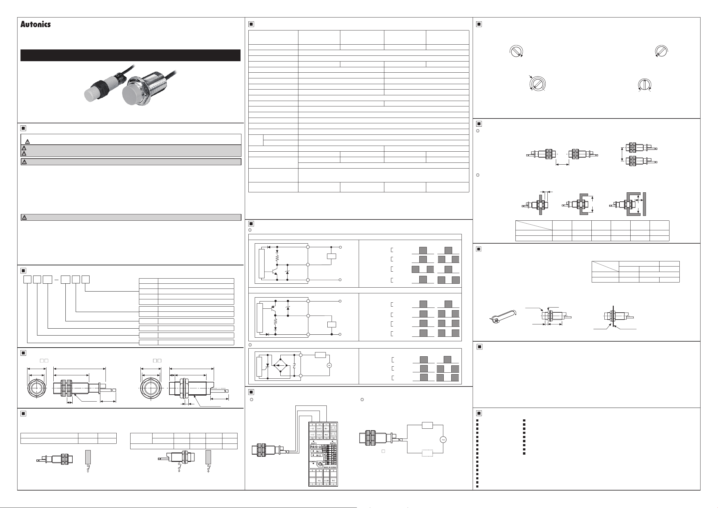
● Please turn poten ion VR to set sensi ivity as below procedure.
①
Without a sensing object, turn the potention VR to the right
and stop at the proximity sensor is ON (OFF).
Stop at ON (OFF) position
③
If the difference of the number of potention VR rota ion
between the ON (OFF) point and the OFF (ON) point is more
than 1.5 turns, the sensing operation will be stable.
※
When here is distance fluctua ion between proximity sensor and he target, please adjust ② at the far hest distance from this unit.
※
Turning potention VR toward clockwise, it will be max., or turning toward counter clockwise, it will be min. The number of adjustment
should be 15±3 revolution and if it is turned to the right or left excessively, it will not stop, but it idles without breakdown.
※
( ) is for Normally closed type.
~
OFF (ON) position
t0 m
Mutual-Interference & Inuence By Surrounding Metals
Mutual-interference
When several proximity sensors are mounted closely, malfunction of sensor may be caused due to mutual interference.
Therefore, be sure to keep a minimum distance between the two sensors, as below charts.
Influence by surrounding metals
When sensors are mounted on metallic panel, it is required to protect the sensors from malfunction by any metallic object.
Therefore, be sure to keep a minimum distance as below charts.
4~:~
Model
CR18 48 54 20 54 24 54
~________'.:::::1========.'.::::1
Installation and Tightening Torque
When tightening the nut, use the provided washer as [Figure 1]
When installing the product, the tightening torque of the nut varies
according to the distance from the fore-end.
The front part of the product is from the fore-end to the dimension on
the below table, and the rear part is from the tip of the nut to the end
of the product. [Figure 2]
In case the nut is placed in the front part of the product, apply
tightening torque for front part.
[Table 1] the allowable tightening torque table is for inserting the
washer as [Figure 3].
[Figure 1] [Figure 2] [Figure 3]
CR30 90 90 10 90 45 90
Fore-end
Cautions During Use
1. Follow instructions in 'Cautions during Use'. Otherwise, it may cause unexpected accidents.
2. 12-24VDC power supply should be insulated and limited voltage/current or Class 2, SELV power supply device.
3. Use the product, after 0.8 sec of supplying power.
4. Wire as short as possible and keep away from high voltage lines or power lines, to prevent surge and inductive noise.
Do not use near the equipment which generates strong magnetic force or high frequency noise (transceiver, etc.).
In case installing the product near the equipment which generates strong surge (motor, welding machine, etc.), use diode or
varistor to remove surge.
5. Do not connect capacity load to he output terminal directly.
6. This unit may be used in the following environments.
Indoors (in the environment condition rated in 'Specifications')
①
Altitude max. 2,000m
②
Pollution degree 2
③
Installation category II
④
Major Products
Photoelectric Sensors Temperature Controllers
Fiber Optic Sensors Temperature/Humidity Transducers
Door Sensors SSRs/Power Controllers
Door Side Sensors Counters
Area Sensors Timers
Proximity Sensors Panel Meters
Pressure Sensors Tachometers/Pulse(Rate)Meters
Rotary Encoders Display Units
Connectors/Sockets Sensor Controllers
Switching Mode Power Supplies
Control Switches/Lamps/Buzzers
I/O Terminal Blocks & Cables
Stepper Motors/Drivers/Motion Controllers
Graphic/Logic Panels
Field Network Devices
Laser Marking System(Fiber, CO₂, Nd:YAG)
Laser Welding/Cutting System
■
■
■
■
■
■
■
■
■
Item
Front Rear
②
Put the object in right sensing position, turn he potention
VR to the left and stop at the proximity sensor is OFF (ON).
Stop at OFF (ON) position
④
If it is set in sensitivity adjustment position of potention
VR at center between ① and ②, sensitivity set ing will be
completed.
It is stable when it is
over 1 5 times
ON (OFF) position
A
Face to face Parallel
ℓ
Ød
A B ℓ Ød m n
=================I
[Table 1]
Strength
Model
CR18
1:s:1
CR30 12mm 49N.m 78.4N.m
Nut tip
Washer
Adjustment completed
OFF (ON) position
B
======I
Front Rear
Size Torque Torque
-
Mounting
bracket
0
ON (OFF) position
m
n
(unit: mm)
==========---I
0 39N.m
1 ! I
_____j
DRW161147AB
 Loading...