

Page 1
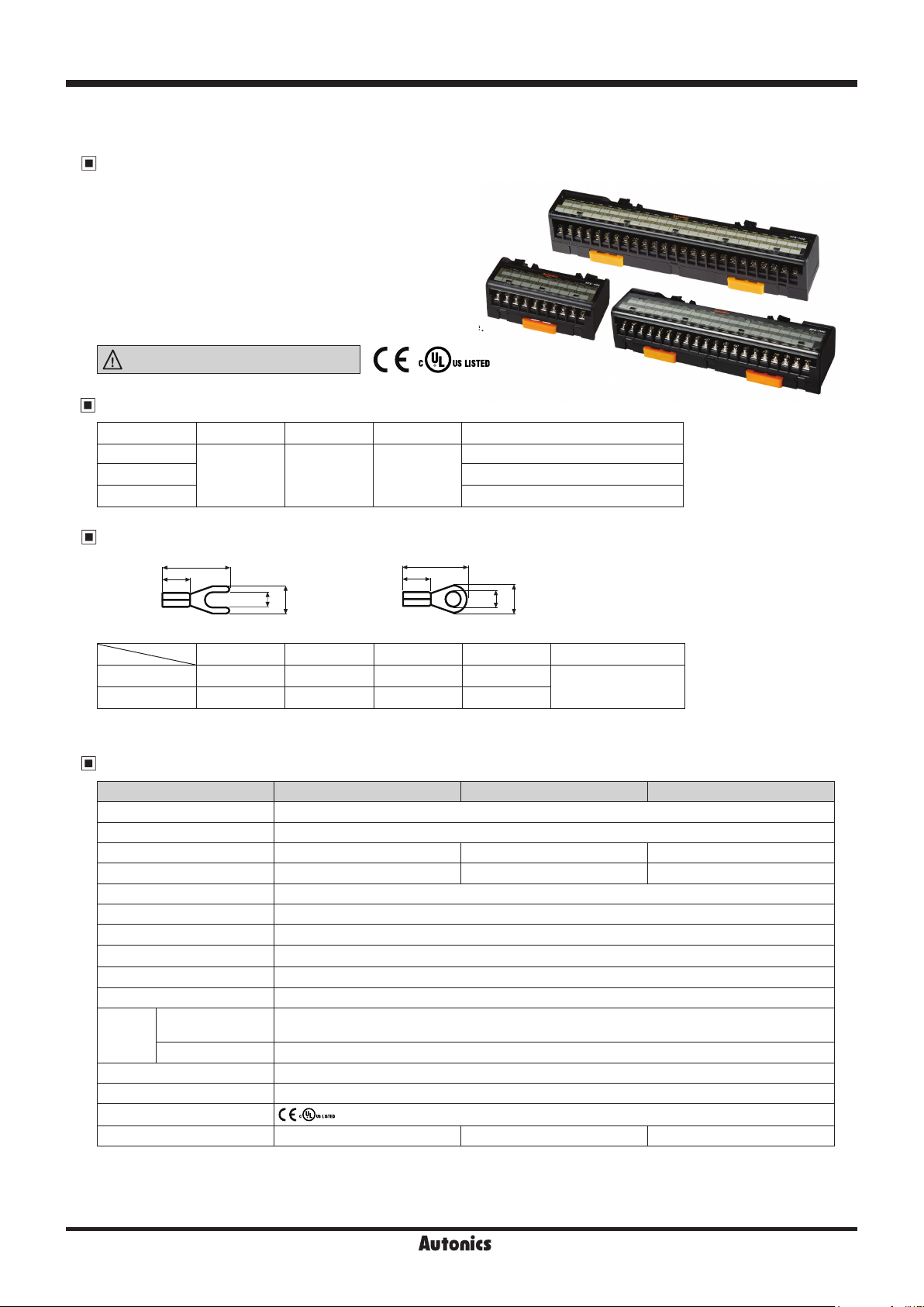
AFS Series
nterface Terminal Block (screw type)
I
Features
Compact interface terminal blocks with 7mm terminal pitch
●
Optimized for connector type PLCs and input/output of
●
dedicated controllers
Compact, space-saving design
●
2 mounting methods (DIN rail, screw mount)
●
※
Autonics I/O cable CJ Series is recommended.
Please refer to ‘I/O cable’ in the I/O terminal block catalogue.
Please read “Safety Considerations” in instruction
manual before using.
Ordering Information
Model Item Terminal type Connector type The number of connector pin
AFS-H20
AFS-H40 40-pin
AFS-H50 50-pin
Interface
terminal block
Screw
Hirose
connector
20-pin
Terminal Specifi cations
B
A
D
C
A B C D Applicable wire
Spade terminal ≥4.1 ≥16.0 ≥3.0 ≤5.9
Ring terminal ≥4.1 ≥16.0 ≥3.0 ≤5.9
※
Please use UL certified terminals.
B
A
D
C
<Ring terminal><Spade terminal>
AWG 22-16
(0.30 to 1.25mm
(unit: mm)
2
)
Specifi cations
Model AFS-H20 AFS-H40 AFS-H50
Power supply ≤125VDCᜡ, 125VACᜠ 50/60Hz
Rated current ≤1A
The number of connector pin 20-pin 40-pin 50-pin
The number of terminal 20 40 50
Terminal pitch 7.0mm
Applicable wire AWG22-16 (0.30 to 1.25mm²)
Insulation resistance ≥1,000MΩ (at 500VDC megger)
Dielectric strength 600VAC 50/60Hz for 1 min
V bration 0.75mm amplitude at frequency of 10 to 55 Hz (for 1 min) in each X, Y, Z direction for 2 hours
Shock 150m/s
2
(approx. 15G)in each X, Y, Z direction for 3 times
Environment
Material Case: MPPO, terminal pin: Brass
Tightening torque 0.5 to 0.6 N·m
Approval
Weight
※
1: The weight includes packaging. The weight in parenthesis is for unit only.
※
Environment resistance is rated at no freezing or condensation.
Ambient temperature -15 to 55℃, storage: -25 to 65
Ambient humidity 35 to 85%RH, storage: 35 to 85%RH
※
1
Approx. 103g (approx. 71g) Approx. 175g (approx. 133g) Approx. 211g (approx. 163g)
A-6
℃
Page 2
Interface Terminal Block
●
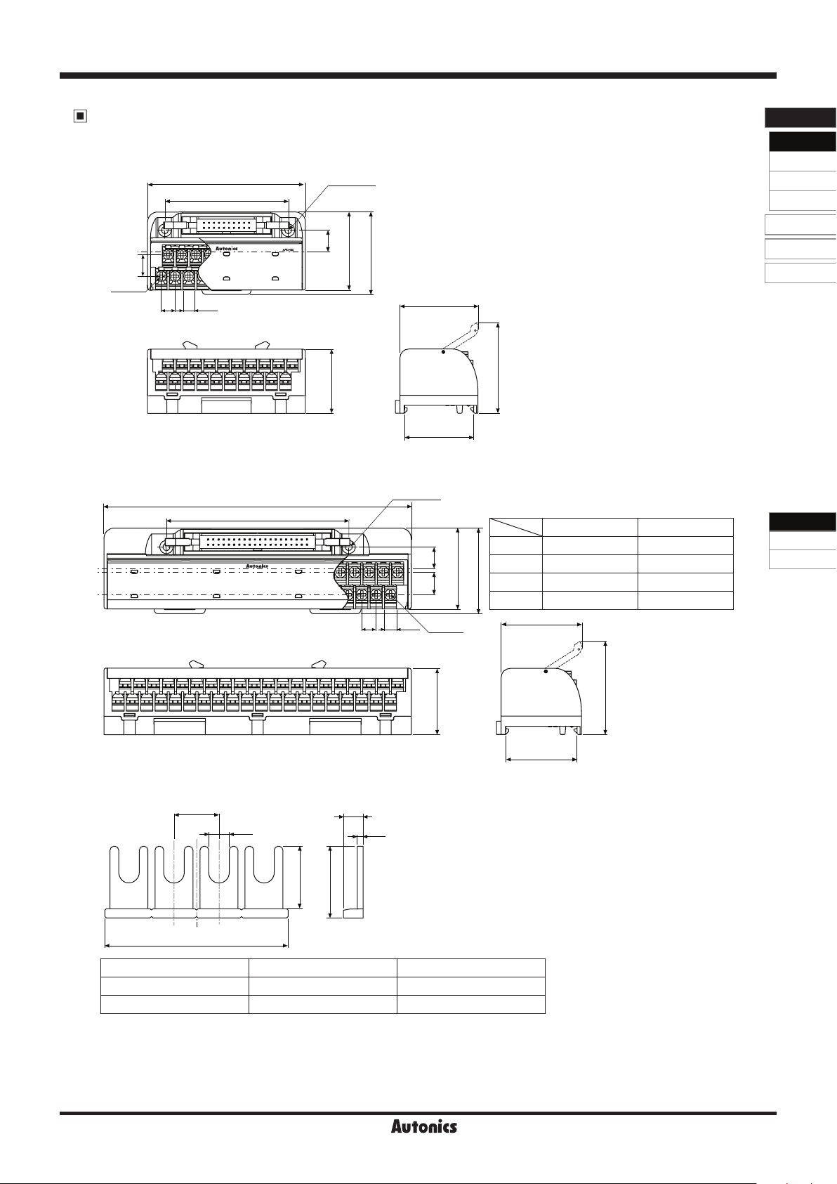
AFS-H20
●
AFS-H40 / AFS-H50
●
Jumper bar (sold separately)
Dimensions
11
20-M3
7
5.9
80
62.5
I/O Termina l Blocks
Inter face
Terminal Blocks
Common
Terminal Blocks
Sensor Connector
Terminal Blocks
Relay
Terminal Blocks
I/O Cables
Remote I /O
Others
2-Ø3.5
10.5
39.5
(unit: mm)
41.8
39.7
45.8
32.5
35.2
A
B
2-Ø3.5
AFS-H40 AFS-H50
A 150 184
10.511
B 89 104
39.5
41.8
C 45.8 48.9
AFS Series
AFL Series
AFR Series
D 39.7 34.8
5.9
40-M3,
50-M3
7
D
7
3.2
9.5
2.7
0.8
10.9
[N]
Model JB-7-04 JB-7-10
The number of Jumper bar pin 4 10
[ N ] size 27.5 69.5
C
32.5
35.2
A-7
Page 3
AFS Series
●
AFS-H20
●
AFS-H40 / AFS-H50
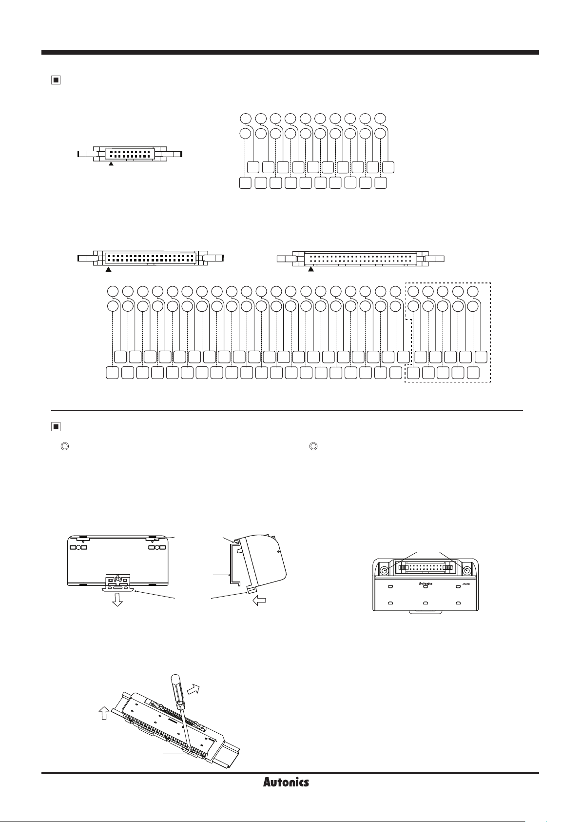
Wire Connections
※
Hirose connector
: HIF3BA-20PA-2.54DSA
2
4 6
Connector
20
2
1
5
3
8
7 9
10 12
11
16 18
14
13 15 17
20
19
1
※
Hirose connector
: HIF3BA-40PA-2.54DSA
2 40
1
4
Connector
2
1 3
Terminal
block
A1 A2 A3 A4 A5 A6 A7 A8 A9
19
Terminal
block
39
8
6
7
5
B2B1 B3 B4 B5 B6 B7 B8 B9
10 12
9 11
14 16
13 15
18
17 19
B2B1B3 B4
A2 A3 A4 A5 A6
A1
※
B5 B6 B7
Hirose connector model
: HIF3BA-50PA-2.54DSA
2
1
20
22
21
B10 B11 B13 B14 B15 B16 B21B17 B22B18 B23B19 B24B20 B25
A10 A11 A12 A13 A14 A15 A16 A21A17 A22A18 A23A19 A24A20 A25
26
24
25 27
23
B12
30 32 42
28
29
B8
A8
A7
34 4436 46
33 4335 45
31 41
B10
B9
A9
A10
38 48
37 4739 49
※
Dot line part is only for AFS-H50 model.
Installation
Mounting and removal at DIN rail Mounting with screws
Mounting
●
1)Pull the rail lock towards direction ①.
2)Attach the DIN rail connection hook onto the DIN
rail.
3)Push the unit towards direction ②, then push the rail
lock in to lock into position.
DIN rail
connection part
1) The unit can be mounted on panels using the
mounting holes next to the hirose connector.
2)M3 × 30mm spring washer screws are
recommended for installation. When using flat
washers, use Ø6mm diameter washers. The
tightening torque should be from 0.5 to 0.7 N·m.
50
49
40 50
Mounting holes
DIN rail
Rail lock
Removal
●
①
1)Insert a screwdriver into the rail lock hole and pull it
towards direction ①.
2)Remove the unit by pulling the unit towards
direction ②.
①
②
Rail lock
A-8
②
Page 4
Interface Terminal Block
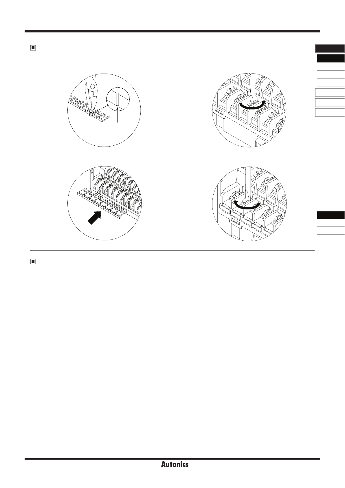
Installing Jumper Bars
1)Cut the jumper bar to the user's desired length by
cutting at the V dent using a nipper.
V dent
3)Insert the jumper bar below the unfastened screws.
2)Unfasten all the screws of the terminals you wish to
commonize.
4)Tighten all the screws above the jumper bar.
I/O Termina l Blocks
Inter face
Terminal Blocks
Common
Terminal Blocks
Sensor Connector
Terminal Blocks
Relay
Terminal Blocks
I/O Cables
Remote I /O
Others
AFS Series
AFL Series
AFR Series
Cautions during Use
1. Do not use the product outside of rated temperature and humidity.
2. Check to make sure that voltage fluctuation in the power supply is within the rated range.
3. When connecting PLC or other controllers, check the power polarity before wiring.
4. Use AWG 16 (1.25mm
5. Do not connect or disconnect the connector or perform any wiring work while supplied with power.
6. Do not use the unit in the following environments.
Environments with high vibration or shock
①
Environments where strong alkalis or acids are used
②
Environments with exposure to direct sunlight
③
Near machinery which produce strong magnetic force or electric noise
④
7. This unit may be used in the following environments.
Indoors
①
Altitude max. 2,000m
②
Pollution degree 2
③
Installation category II
④
2
) wire and use appropriate connectors for the terminals.
A-9
 Loading...